Page 227 of 4087
PREPARATION
SST (SPECIAL SERVICE TOOLS)
09082±00700SRS Airbag
Deployment Tool
09213±31021Crankshaft Pulley
Puller
09843±18020Diagnosis Check
Wiring
Steering wheel
RECOMMENDED TOOLS
09042±00010Torx Socket
T30
09042±00020Torx Socket
T30
09082±00015TOYOTA
Electrical Tester
Center airbag sensor assembly
Steering wheel pad
EQUIPMENT
Part NameNote
Torque wrench
AB±13SRS AIRBAG ± Preparation
WhereEverybodyKnowsYourName
Page 228 of 4087

REMOVAL AND INSTALLATION OF
COMPONENT PARTS
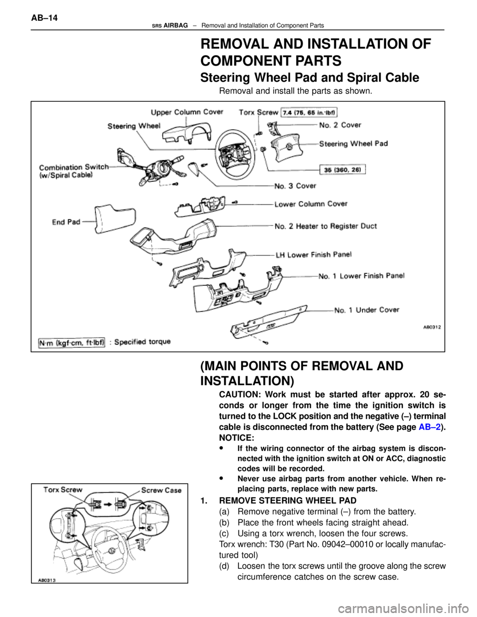
Steering Wheel Pad and Spiral Cable
Removal and install the parts as shown.
(MAIN POINTS OF REMOVAL AND
INSTALLATION)
CAUTION: Work must be started after approx. 20 se-
conds or longer from the time the ignition switch is
turned to the LOCK position and the negative (±) terminal
cable is disconnected from the battery (See page AB±2).
NOTICE:
wIf the wiring connector of the airbag system is discon-
nected with the ignition switch at ON or ACC, diagnostic
codes will be recorded.
wNever use airbag parts from another vehicle. When re-
placing parts, replace with new parts.
1. REMOVE STEERING WHEEL PAD (a) Remove negative terminal (±) from the battery.
(b) Place the front wheels facing straight ahead.
(c) Using a torx wrench, loosen the four screws.
Torx wrench: T30 (Part No. 09042±00010 or locally manufac-
tured tool)
(d) Loosen the torx screws until the groove along the screwcircumference catches on the screw case.
AB±14
SRS AIRBAG
± Removal and Installation of Component Parts
WhereEverybodyKnowsYourName
Page 229 of 4087

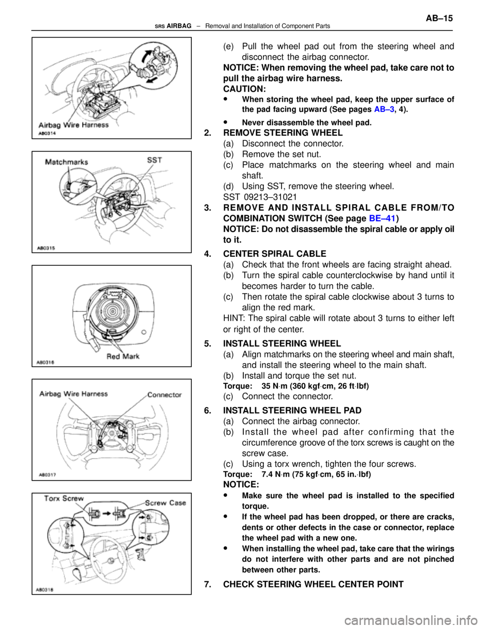
(e) Pull the wheel pad out from the steering wheel anddisconnect the airbag connector.
NOTICE: When removing the wheel pad, take care not to
pull the airbag wire harness.
CAUTION:
wWhen storing the wheel pad, keep the upper surface of
the pad facing upward (See pages AB±3, 4).
wNever disassemble the wheel pad.
2. REMOVE STEERING WHEEL
(a) Disconnect the connector.
(b) Remove the set nut.
(c) Place matchmarks on the steering wheel and mainshaft.
(d) Using SST, remove the steering wheel.
SST 09213±31021
3. REMOVE AND INSTALL SPIRAL CABLE FROM/TO COMBINATION SWITCH (See page BE±41)
NOTICE: Do not disassemble the spiral cable or apply oil
to it.
4. CENTER SPIRAL CABLE (a) Check that the front wheels are facing straight ahead.
(b) Turn the spiral cable counterclockwise by hand until it
becomes harder to turn the cable.
(c) Then rotate the spiral cable clockwise about 3 turns to align the red mark.
HINT: The spiral cable will rotate about 3 turns to either left
or right of the center.
5. INSTALL STEERING WHEEL (a) Align matchmarks on the steering wheel and main shaft,
and install the steering wheel to the main shaft.
(b) Install and torque the set nut.
Torque: 35 N Vm (360 kgf Vcm, 26 ft Vlbf)
(c) Connect the connector.
6. INSTALL STEERING WHEEL PAD (a) Connect the airbag connector.
(b) I n s t a l l t h e w heel pad after confirming that the
circumference groove of the torx screws is caught on the
screw case.
(c) Using a torx wrench, tighten the four screws.
Torque: 7.4 N Vm (75 kgf Vcm, 65 in. Vlbf)
NOTICE:
wMake sure the wheel pad is installed to the specified
torque.
wIf the wheel pad has been dropped, or there are cracks,
dents or other defects in the case or connector, replace
the wheel pad with a new one.
wWhen installing the wheel pad, take care that the wirings
do not interfere with other parts and are not pinched
between other parts.
7. CHECK STEERING WHEEL CENTER POINT AB±15
SRS AIRBAG
± Removal and Installation of Component Parts
WhereEverybodyKnowsYourName
Page 230 of 4087
Front Airbag Sensor
Remove and install the parts as shown.
(MAIN POINTS OF REMOVAL AND
INSTALLATION)
CAUTION: Work must be started after approx. 20 se-
conds or longer from the time the ignition switch is
turned to the LOCK position and the negative (±) terminal
cable is disconnected from the battery (See page AB±2).
NOTICE:
wIf the wiring connector of the airbag system is discon-
nected with the ignition switch at ON or ACC, diagnostic
codes will be recorded.
wNever use airbag parts from another vehicle. When
replacing parts, replace with new parts.
wNever reuse the sensor involved in a collision when the
airbag has deployed.
wNever repair a sensor in order to reuse it.
AB±16SRS AIRBAG ± Removal and Installation of Component Parts
WhereEverybodyKnowsYourName
Page 233 of 4087

(MAIN POINTS OF REMOVAL AND
INSTALLATION)
CAUTION: Work must be started after approx. 20 se-
conds or longer from the time the ignition switch is
turned to the LOCK position and the negative (±) terminal
cable is disconnected from the battery (See page AB±2).
NOTICE:
wDo not open the cover or the case of the ECU and various
computers unless absolutely necessary. (If the IC termi-
nals are touched, the IC may be destroyed by static elec-
tricity.)
wNever use airbag parts from another vehicle. When
replacing parts, replace with new parts.
wNever reuse the center airbag sensor assembly involved
in a collision when the airbag has deployed.
wNever repair a sensor in order to reuse it.
REMOVE AND INSTALL CENTER
AIRBAG SENSOR ASSEMBLY
(a) Using a torx wrench, loosen and tighten the three screws.
Torx wrench: T40 (Part No. 09042±00020 or locally manufac-
tured tool)
Torque: 13 N Vm (130 kgf Vcm, 9 ft Vlbf)
NOTICE:
wMake sure the sensor assembly is installed to the speci-
fied torque.
wIf the sensor assembly has been dropped, or there are
cracks, dents or other defects in the case, bracket or
connector, replace the sensor assembly with a new one.
wWhen installing the sensor assembly, take care that the
airbag wiring does not interfere with other parts and is
not pinched between other parts.
wAfter installation, shake the sensor assembly to check
that there is no looseness.
(b) Disconnect the connector. AB±19
SRS AIRBAG
± Removal and Installation of Component Parts
WhereEverybodyKnowsYourName
Page 247 of 4087
Wiring Diagram
CENTER AIRBAG SENSOR ASSEMBLY CONNECTOR
No.SymbolTerminal NameNo.SymbolTerminal Name
18E2Ground
2±SRRH Front Airbag Sensor (±)9LAAirbag Warning Light
3+SRRH Front Airbag Sensor (+)10D±Squib (±)
4+SLLH Front Airbag Sensor (+)11D+Squib (+)
5±SLLH Front Airbag Sensor (±)12TcDiagnosis
6+BBattery (ECU±B Fuse)13E1Ground
7IG2Power Source (IGN Fuse)14AccPower Source (CIG Fuse)
AL1Electrical Connection Check
MechanismBL2Electrical Connection Check
Mechanism
AB±33SRS AIRBAG ± Troubleshooting
WhereEverybodyKnowsYourName
Page 254 of 4087

Circuit Inspection
Diag. Code (Normal)Source Voltage Drop
CIRCUIT DESCRIPTION
The airbag system is equipped with a voltage±increase circuit (DC±DC\
converter) in the center airbag
sensor assembly in case the source voltage drops.
When the battery voltage drops, the voltage±increase circuit (DC±DC c\
onverter) functions to increase
the voltage of the airbag system to normal voltage.
The diagnosis system malfunction display for this circuit is different to other circuits±when the airbag
warning light remains lit up and the diagnostic code is a normal code, source voltage d\
rop is indicated.
Malfunction in this circuit is not recorded in the center airbag sensor assembly, and approx. 10 se-
conds after the source voltage returns to normal, the airbag warning lig\
ht automatically goes off.
Code No.
Diagnosis
(Normal)Source voltage drop.
DIAGNOSTIC CHART
Preparation.
Does airbag warning light turn on after
approx. 10 seconds?
Check battery and charging system
(See page CH±1). Check diagnostic code, and if a
malfunction code is output,
perform troubleshooting according
to malfunction code.
If a normal code is output,
replace center airbag sensor
assembly.
WIRING DIAGRAM
AB±40SRS AIRBAG
± Troubleshooting
WhereEverybodyKnowsYourName
Page 257 of 4087
DIAGNOSTIC CHART (Cont'd)
Check front airbag sensor.Replace front airbag sensor.
Repair or replace spiral cable.Check spiral cable. Repair or replace harness or connector
between center airbag sensor assembly and
front airbag sensor (See page AB±20).
Repair or replace harness or connector
between center airbag sensor assembly and
spiral cable.
WIRING DIAGRAM
AB±43SRS AIRBAG ± Troubleshooting
WhereEverybodyKnowsYourName