Page 130 of 4087

������������������\
������������������\
�
������������������\
�����������������
������������������\
������������������\
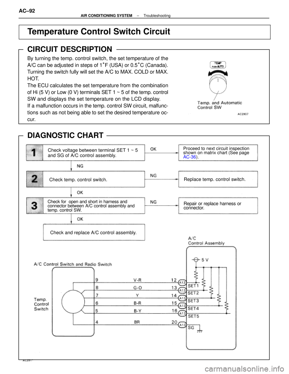
Temperature Control Switch Circuit
CIRCUIT DESCRIPTION
By turning the temp. control switch, the set temperature of the
A/C can be adjusted in steps of 1
°F (USA) or 0.5 °C (Canada).
Turning the switch fully will set the A/C to MAX. COLD or MAX.
HOT.
The ECU calculates the set temperature from the combination
of Hi (5 V) or Low (0 V) terminals SET 1 ~ 5 of the temp. control
SW and displays the set temperature on the LCD display.
If a malfunction occurs in the temp. control SW circuit, malfunc-
tions such as not being able to set the desired temperature oc-
cur.
DIAGNOSTIC CHART
WIRING DIAGRAM
Check for open and short in harness and
connector between A/C control assembly and
temp. control SW.
Check temp. control switch.
Proceed to next circuit inspection
shown on matrix chart (See page
AC-36 ).
Replace temp. control switch.
Repair or replace harness or
connector.
Check and replace A/C control assembly.
Check voltage between terminal SET 1 ~ 5
and SG of A/C control assembly.
AC±92±
AIR CONDITIONING SYSTEM Troubleshooting
WhereEverybodyKnowsYourName
Page 135 of 4087
������������������\
������������������\
�
������������������\
�����������������
������������������\
������������������\
Diagnosis Circuit
CIRCUIT DESCRIPTION
This circuit sends signals to the A/C control assembly requesting output of \
diagnostic codes.
DIAGNOSTIC CHART
WIRING DIAGRAM
Check voltage between terminals Tc and
E1 of TDCL.
Check harness and connector between air
conditioner control assembly and TDCL and
body ground.
Proceed to next circuit inspection
shown on matrix chart (See page
AC-36
).
Repair or replace harness or
connector.
Check and replace air conditioner control
assembly.
AC±98±
AIR CONDITIONING SYSTEM Troubleshooting
WhereEverybodyKnowsYourName
Page 179 of 4087
Preperation.
Check squib circuit.
Check spiral cable.Check harness between center airbag
sensor assembly and spiral cable.
Check center airbag sensor assembly.
Check squib.
From the results of the above inspection, the
malfunctioning part can now be considered
normal. To make sure of this, use the simula-
tion method to check. Go to step
Repair or replace spiral cable.
Repair or replace harness or con-
nector between center airbag sen-
sor assembly and spiral cable. Replace center airbag
sensor assembly
Replace steering wheel pad.
WIRING DIAGRAM
DIAGNOSTIC CHARTDIAGNOSTIC CHART
±
SRS AIRBAG TroubleshootingAB±63
WhereEverybodyKnowsYourName
Page 185 of 4087
Preperation.
Check front airbag sensor circuit.
(Measure resistance between terminals +SR
and ±SR, +SL and ±SL of center airbag sen-
sor assembly connector.)
Check center airbag sensor assembly.From the results of the above inspection, the
malfunctioning part can now be considered nor-
mal. To make sure of this, use the simulation
method to check.
Check front airbag sensor.
Check harness between center airbag
sensor assembly and front airbag sensor.
Replace front airbag sensor connector
(See page AB±20). Replace center airbag sensor
assembly. Go to step
Replace front airbag sensor.
Repair or replace harness or con-
nector between center airbag sen-
sor assembly and front airbag sen-
sor (See page AB±20).
WIRING DIAGRAM
DIAGNOSTIC CHARTDIAGNOSTIC CHART
±
SRS AIRBAG TroubleshootingAB±69
WhereEverybodyKnowsYourName
Page 192 of 4087
YESNO
1
Replace center airbag sensor assembly. Using simulation method,
reproduce malfunction symptoms
(See page
IN±20).
WIRING DIAGRAM
Is diagnostic code 22 output again?
DIAGNOSTIC CHART
HINT: If diagnostic code 22 is output, perform the following troubleshooting:\
AB±76
±
SRS AIRBAG Troubleshooting
WhereEverybodyKnowsYourName
Page 198 of 4087

OK
Check operation of airbag warning light.
NG1
WIRING DIAGRAM
2Is diagnostic code 41 output again? System is normal.
Check harness between ECU±B
fuse and center airbag sensor as-
sembly. If normal, replace center
airbag sensor assembly.
Perform troubleshooting according to
malfunction code output. NO
YES
Diag. Code 41Malfunction Stored in Memory
CIRCUIT DESCRIPTION
If a malfunction occurs in the airbag system, malfunction codes 11 to 31 may be output, and when the
battery is disconnected after the malfunction is repaired, malfunction codes 11 to 31 will be cleared,
but code 41 will be output instead.
So long as the cancellation operation for a malfunction stored in memory (\
See page
AB±32) is not per-
formed, code 41 is stored in the center airbag sensor assembly and the airbag w\
arning light remains
lit up.
Code No.Diagnosis
41 � Malfunction recorded in memory.41 � Center airbag sensor assembly malfunction.
DIAGNOSTIC CHART
AB±82±
SRS AIRBAG Troubleshooting
WhereEverybodyKnowsYourName
Page 200 of 4087
YES
Does airbag warning light turn off?
NO
1
Replace center airbag sensor assembly. Check airbag warning light circuit
or terminal AB circuit of TDCL or
check connector.
WIRING DIAGRAM
Airbag Warning Light System (Always Lit Up)
CIRCUIT DESCRIPTION
The airbag warning light is located on the combination meter.
When the airbag system is normal, the airbag warning light lights up for\
approx. 6 seconds after the
ignition switch is turned from LOCK position to ACC or ON position, and then turns off automatically.
If there is a malfunction in the airbag system, the airbag warning light\
lights up to inform the driver of
the abnormality.
When terminals Tc and E of the TDCL are connected, the diagnostic code is displayed by t\
he blinking
of the airbag warning light.
DIAGNOSTIC CHART
AB±84±
SRS AIRBAG Troubleshooting
WhereEverybodyKnowsYourName
Page 203 of 4087
WIRING DIAGRAM
DIAGNOSTIC CHART
±
SRS AIRBAG TroubleshootingAB±87
WhereEverybodyKnowsYourName