Page 553 of 4087
ELECTRIC TENSION REDUCER
SYSTEM
Parts Location
Wiring and Connector Diagrams
±
BODY ELECTRICAL SYSTEM Electronic Tension Reducer SystemBE±167
WhereEverybodyKnowsYourName
Page 554 of 4087

Parts Inspection
(Tension Reducer Solenoid)
REMOVAL AND INSTALLATION OF
TENSION REDUCER SOLENOID
(See page BO±71)
INSPECTION OF TENSION REDUCER
SOLENOID
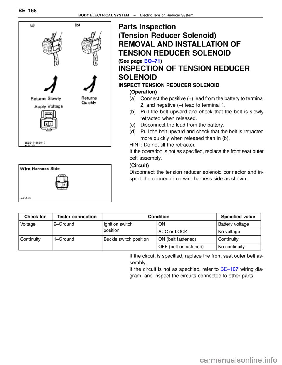
INSPECT TENSION REDUCER SOLENOID
(Operation)
(a) Connect the positive (+) lead from the battery to terminal
2, and negative (±) lead to terminal 1.
(b) Pull the belt upward and check that the belt is slowly retracted when released.
(c) Disconnect the lead from the battery.
(d) Pull the belt upward and check that the belt is retracted
more quickly when released than in (b).
HINT: Do not tilt the retractor.
If the operation is not as specified, replace the front seat outer
belt assembly.
(Circuit)
Disconnect the tension reducer solenoid connector and in-
spect the connector on wire harness side as shown.
Check forTester connectionConditionSpecified value
Voltage2±GroundIgnition switchONBattery voltagegg
positionACC or LOCKNo voltage
Continuity1±GroundBuckle switch positionON (belt fastened)Continuityy
OFF (belt unfastened)No continuity
If the circuit is specified, replace the front seat outer belt as-
sembly.
If the circuit is not as specified, refer to BE±167 wiring dia-
gram, and inspect the circuits connected to other parts.
BE±168
±
BODY ELECTRICAL SYSTEM Electric Tension Reducer System
WhereEverybodyKnowsYourName
Page 555 of 4087

(Buckle Switch)
REMOVAL AND INSTALLATION OF
BUCKLE SWITCH
1. REMOVE BUCKLE SWITCH(a) Remove the driver or front passenger's seat.
(b) Disconnect buckle switch connector.
(c) Remove seat belt inner with buckle switch.
2. INSTALL BUCKLE SWITCH For installation follow the removal procedure in reverse.
INSPECTION OF BUCKLE SWITCH
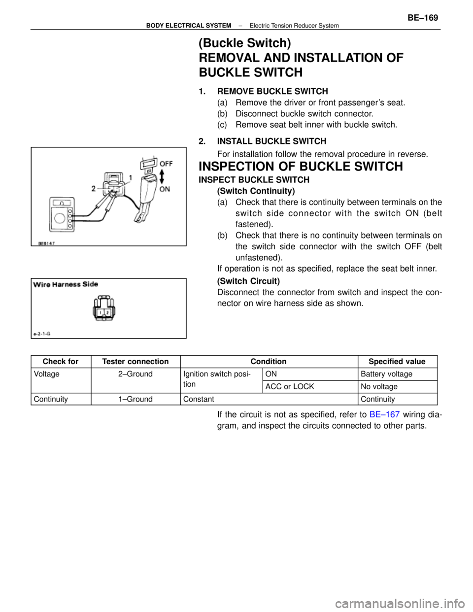
INSPECT BUCKLE SWITCH(Switch Continuity)
(a) Check that there is continuity between terminals on theswitch side connector with the switch ON (belt
fastened).
(b) Check that there is no continuity between terminals on the switch side connector with the switch OFF (belt
unfastened).
If operation is not as specified, replace the seat belt inner.
(Switch Circuit)
Disconnect the connector from switch and inspect the con-
nector on wire harness side as shown.
Check forTester connectionConditionSpecified value
Voltage2±GroundIgnition switch posi-ONBattery voltagegg
tionACC or LOCKNo voltage
Continuity1±GroundConstantContinuity
If the circuit is not as specified, refer to BE±167 wiring dia-
gram, and inspect the circuits connected to other parts.
±
BODY ELECTRICAL SYSTEM Electric Tension Reducer SystemBE±169
WhereEverybodyKnowsYourName
Page 558 of 4087
Wiring and Connector Diagrams
Parts Inspection
(Defogger Switch)
REMOVAL AND INSTALLATION OF AIR
CONDITIONER CONTROL PANEL
ASSEMBLY
(See Instrument Panel on page BO±111)
INSPECTION OF DEFOGGER SWITCH
INSPECT SWITCH OPERATION
(a) Connect the positive (+) lead from the battery to terminal
A6 and negative (±) lead to terminal A7.
(b) Connect the positive (+) lead from the battery to terminal
B10 through a 1.4 W test bulb.
BE±172
±
BODY ELECTRICAL SYSTEM Defogger System
WhereEverybodyKnowsYourName
Page 564 of 4087
Wiring and Connector Diagrams
BE±178±
BODY ELECTRICAL SYSTEM Sliding Roof System
WhereEverybodyKnowsYourName
Page 571 of 4087
Wiring and Connector Diagrams (Cont'd)
±
BODY ELECTRICAL SYSTEM Power Mirror Control SystemBE±185
WhereEverybodyKnowsYourName
Page 577 of 4087
FUEL LID OPENER SYSTEM
Parts Location
Wiring and Connector Diagrams
±
BODY ELECTRICAL SYSTEM Fuel Lid Opener SystemBE±191
WhereEverybodyKnowsYourName
Page 585 of 4087
Wiring and Connector Diagrams
±
BODY ELECTRICAL SYSTEM Audio SystemBE±199
WhereEverybodyKnowsYourName