Page 2770 of 4087

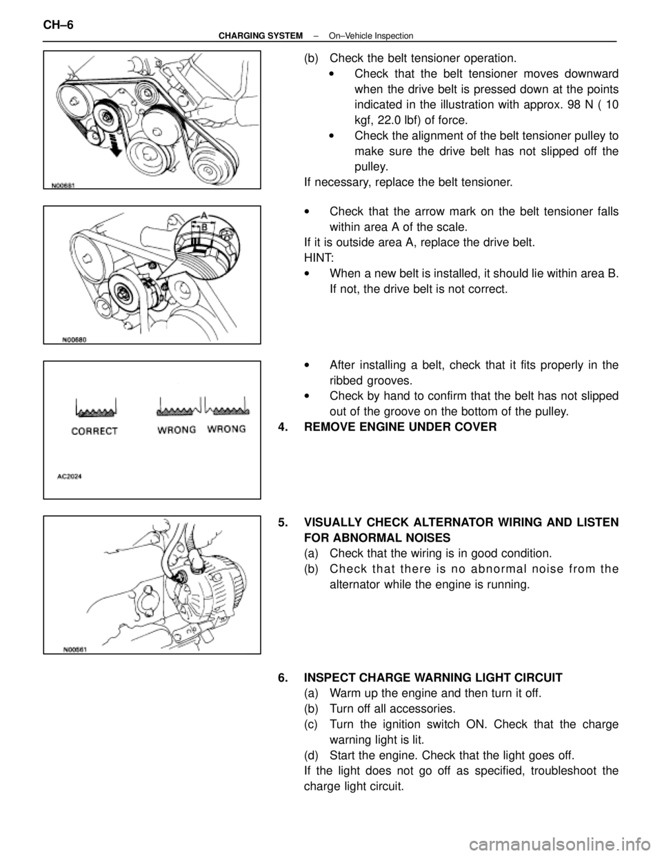
(b) Check the belt tensioner operation.w Check that the belt tensioner moves downward
when the drive belt is pressed down at the points
indicated in the illustration with approx. 98 N ( 10
kgf, 22.0 lbf) of force.
w Check the alignment of the belt tensioner pulley to
make sure the drive belt has not slipped off the
pulley.
If necessary, replace the belt tensioner.
w Check that the arrow mark on the belt tensioner falls
within area A of the scale.
If it is outside area A, replace the drive belt.
HINT:
w When a new belt is installed, it should lie within area B.
If not, the drive belt is not correct.
w After installing a belt, check that it fits properly in the
ribbed grooves.
w Check by hand to confirm that the belt has not slipped
out of the groove on the bottom of the pulley.
4. REMOVE ENGINE UNDER COVER
5. VISUALLY CHECK ALTERNATOR WIRING AND LISTEN FOR ABNORMAL NOISES
(a) Check that the wiring is in good condition.
(b) C h e c k t h a t t h e r e i s n o a bnormal noise from the
alternator while the engine is running.
6. INSPECT CHARGE WARNING LIGHT CIRCUIT (a) Warm up the engine and then turn it off.
(b) Turn off all accessories.
(c) Turn the ignition switch ON. Check that the charge
warning light is lit.
(d) Start the engine. Check that the light goes off.
If the light does not go off as specified, troubleshoot the
charge light circuit.
CH±6
±
CHARGING SYSTEM On±Vehicle Inspection
WhereEverybodyKnowsYourName
Page 2771 of 4087

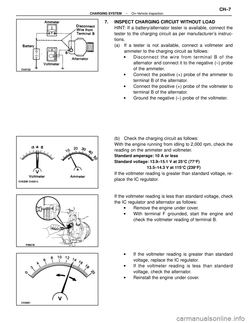
7. INSPECT CHARGING CIRCUIT WITHOUT LOADHINT: If a battery/alternator tester is available, connect the
tester to the charging circuit as per manufacturer's instruc-
tions.
(a) If a tester is not available, connect a voltmeter andammeter to the charging circuit as follows:
w Disconnect the wire from terminal B of the
alternator and connect it to the negative (±) probe
of the ammeter.
w Connect the positive (+) probe of the ammeter to
terminal B of the alternator.
w Connect the positive (+) probe of the voltmeter to
terminal B of the alternator.
w Ground the negative (±) probe of the voltmeter.
(b) Check the charging circuit as follows:
With the engine running from idling to 2,000 rpm, check the
reading on the ammeter and voltmeter.
Standard amperage: 10 A or less
Standard voltage: 13.9±15.1 V at 25 5C (77 5F)
13.5±14.3 V at 115 5C (239 5F)
If the voltmeter reading is greater than standard voltage, re-
place the IC regulator.
If the voltmeter reading is less than standard voltage, check
the IC regulator and alternator as follows:
w Remove the engine under cover.
w With terminal F grounded, start the engine and
check the voltmeter reading of terminal B.
w If the voltmeter reading is greater than standard
voltage, replace the IC regulator.
w If the voltmeter reading is less than standard
voltage, check the alternator.
w Reinstall the engine under cover.
±
CHARGING SYSTEM On±Vehicle InspectionCH±7
WhereEverybodyKnowsYourName
Page 2772 of 4087
8. INSPECT CHARGING CIRCUIT WITH LOAD(a) With the engine running at 2,000 rpm, turn on the highbeam headlights and place the heater blower switch at
ºHIº.
(b) Check the reading on the ammeter.
Standard amperage: 30 A or more
If the ammeter reading is less than standard amperage, re-
pair the alternator. (See page CH±9)
HINT: With the battery fully charged, the indication will some-
times be less than standard amperage.
9. REINSTALL ENGINE UNDER COVER
CH±8
±
CHARGING SYSTEM On±Vehicle Inspection
WhereEverybodyKnowsYourName
Page 2773 of 4087
ALTERNATOR
COMPONENTS FOR REMOVAL AND
INSTALLATION
REMOVAL OF ALTERNATOR
1. DISCONNECT CABLE FROM NEGATIVE TERMINAL OFBATTERY
CAUTION: Work must be started after approx. 20 se-
conds or longer from the time the ignition switch is
turned to the ºLOCKº position and the negative (±) termi-
nal cable is disconnected from the battery.
2. REMOVE ENGINE UNDER COVER
3. REMOVE DRIVE BELT
Loosen the belt tension by turning the drive belt tensioner
counterclockwise, and remove the drive belt.
HINT: The pulley bolt for the belt tensioner has a left±hand
thread.
±
CHARGING SYSTEM AlternatorCH±9
WhereEverybodyKnowsYourName
Page 2784 of 4087
INSTALLATION OF ALTERNATOR
(See Components on page CH±9)
1. INSTALL ALTERNATOR (a) Install the alternator and A/T oil cooler bracket with the
bolt and nut.
Torque: 37 N Vm (380 kgf Vcm, 27 ft Vlbf)
(b) Connect the alternator connector.
(c) Connect the alternator wire with the nut and cap.
2. INSTALL DRIVE BELT Install the drive belt by turning the drive belt tensioner coun-
terclockwise.
HINT: The pulley bolt for the belt tensioner has a left±hand
thread.
3. CONNECT CABLE TO NEGATIVE TERMINAL OF BATTERY
4. PERFORM ON±VEHICLE INSPECTION (See steps 6 to 8 on pages CH±6 to 8)
5. INSTALL ENGINE UNDER COVER
CH±20
±
CHARGING SYSTEM Alternator
WhereEverybodyKnowsYourName
Page 2787 of 4087
DESCRIPTION
This engine utilizes a pressurized forced circulation cooling system which i\
ncludes a hermostat equipped
with a by±pass valve mounted on the inlet side. The cooling system is composed of the water jacket (inside the cylinder bl\
ock and cylinderhead), radiator,
water pump, thermostat, cooling fan, hoses and other components.
OPERATION
CO±2±
COOLIING SYSTEM Description
WhereEverybodyKnowsYourName
Page 2788 of 4087
DESCRIPTION
This engine utilizes a pressurized forced circulation cooling system whi\
ch includes a hermostat equipped
with a by±pass valve mounted on the inlet side. The cooling system is composed of the water jacket (inside the cylinder bl\
ock and cylinderhead), radiator,
water pump, thermostat, cooling fan, hoses and other components.
OPERATION
CO±2±
COOLIING SYSTEM Description
WhereEverybodyKnowsYourName
Page 2789 of 4087

Coolant which is heated in the water jacket is pumped to the radiator, through which a cooling fan blows
air to cool the coolant as it passes through. Coolant which has been coo\
led is then sent back to the engine by
the water pump, where it cools the engine. The water jacket is a network of channels in the shell of the cylinder bloc\
k and cylinderhead through which
coolant passes. It is designed to provide adequate cooling through the cylinders and combus\
tion chambers
which become heated during engine operation.
RADIATOR The radiator performs the function of cooling the coolant which has pass\
ed through the waterjacket and
become hot, and it is mounted in the front of the vehicle. The radiator consis\
ts of an upper tank and lower tank,
and a core which connects the two tanks. The upper tank contains the inlet \
for coolant from the water jacket
and the filler inlet. It also has a hose attached through which excess cool\
ant or steam can flow. The lower tank
contains the outlet for coolant and drain plug. The core contains many t\
ubes through which coolant flows from
the upper tank to the lower tank as well as cooling fins which radiate heat\
away from the coolant in the tubes.
The air sucked through the radiator by the cooling fan, as well as the wind generated by the ve\
hicle's travel,
passes through the radiator, cooling the coolant. Models with automatic transmission include an aut\
omatic
transmission fluid cooler built into the lower tank of the radiator. A cooling fan is mounted behind radiator to assist
the flow of air through the radiator. When the coolant temperature is low, the fan operates slowly to help the warm
up, and when the coolant temperature becomes high, the fan speed is increas\
ed to provide the air flow required
for cooling.
RADIATOR CAP (on Reservoir Tank)
The radiator cap is a pressure type cap which seals the radiator, resulting in pressurization of the radiator
as the coolant expands. The pressurization prevents the coolant from boi\
ling even when the coolant tempera-
ture exceeds 100 5C (212 5F). A relief valve (pressurization valve) and a vacuum valve (negati\
ve pressure valve)
are built into the radiator cap. The relief valve opens and lets steam esca\
pe through the overflow pipe when
the pressure generated inside the cooling system exceeds the limit (coolant temperature: 110±120 5C
(230±248 5F) pressure; 29.4±98.1 kPa (0.3±1.0 kgf/cm2, 4.3±14.2 psi)). The vacuum v\
alve opens to alleviate
the vacuum which develops in the coolant system after the engine is stopped\
and the coolant temperature
drops.
RESERVOIR TANK The purpose of the reservoir tank is to catch coolant overflows created by \
volumetrix expansion when the
coolant temperature increases. The cap of the reservoir tank is a pressure type\
which prevents deterioration
of the LLC (Long Life Coolant) caused by contact with atmospheric air, increases vaporization performance and
reduces loss of the coolant volume.
WATER PUMP The water pump is mounted on the front of the cylinder block and driven by t\
he reverse side of the timing
belt.
THERMOSTAT The thermostat has a wax type by±pass valve and is mounted in the wat\
er inlet housing. The thermostat
begins to open at the temperature of 80 5C (180 5F). When the coolant temperature is low, the valve closes to
prevent coolant flow to the radiator, thus permitting the engine to warm up rapidly. When the by±pass valve
opens the by±pass circuit, the engine coolant continues to circulate \
inside the engine, quickly and uniformly
warming up to the appropriate temperature. When the coolant temperature is high\
, the valve opens and coolant
flows to the radiator where it is cooled. When the wax inside the thermostat \
is heated, it expands and thus
creates pressure which overpowers the force of the spring which keeps the valve\
closed. When the wax cools,
its contraction causes the force of the spring to take effect once more, closing the valve.
ELECTRONICALLY CONTROLLED HYDRAULIC COOLING FAN (See page CO±22)
±
COOLIING SYSTEM DescriptionCO±3
WhereEverybodyKnowsYourName