Page 2756 of 4087
±MEMO±
±
ENGINE TROUBLESHOOTING Circuit InspectionTR±145
WhereEverybodyKnowsYourName
Page 2757 of 4087

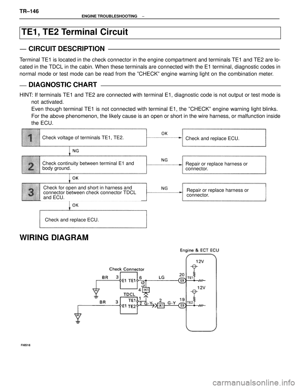
TE1, TE2 Terminal Circuit
CIRCUIT DESCRIPTION
Terminal TE1 is located in the check connector in the engine compartment and terminals T\
E1 and TE2 are lo-
cated in the TDCL in the cabin. When these terminals are connected with \
the E1 terminal, diagnostic codes in
normal mode or test mode can be read from the ºCHECKº engine warning lig\
ht on the combination meter.
DIAGNOSTIC CHARTDIAGNOSTIC CHART
HINT: If terminals TE1 and TE2 are connected with terminal E1, diagnostic code is not output or test mode isnot activated.
Even though terminal TE1 is not connected with terminal E1, the ºCHEC\
Kº engine warning light blinks.
For the above phenomenon, the likely cause is an open or short in the wire \
harness, or malfunction inside
the ECU.
Check continuity between terminal E1 and
body ground.
Repair or replace harness or
connector.Check for open and short in harness and
connector between check connector TDCL
and ECU.
Check voltage of terminals TE1, TE2.
Check and replace ECU.
Repair or replace harness or
connector.
Check and replace ECU.
WIRING DIAGRAM
TR±146±
ENGINE TROUBLESHOOTING
WhereEverybodyKnowsYourName
Page 2758 of 4087
NGOK
OKNG
OKNG
INSPECTION PROCEDURE
1Check voltage between terminals TE1, TE2 and E1 of check connector, TDCL.
C
OK
PTurn ignition switch on.
Measure voltage between terminals TE1, TE2 and E1
of check connector, TDCL.
Voltage: 10 ± 14 V
Check and replace engine & ECT ECT.
2Check continuity between terminal E1 of check connector, TDCL and body ground.
Repair or replace harness or connector.
3
Check for open and short in harness and connector between engine & ECT ECU and che\
ck con-
nector, TDCL (See page IN±27).
Repair or replace harness or connector.
Check and replace engine & ECT ECU.
±
ENGINE TROUBLESHOOTING Circuit InspectionTR±147
WhereEverybodyKnowsYourName
Page 2765 of 4087
DESCRIPTION
The alternator is a small, high±rpm, high±performance type with an IC\
regulator incorporated. The IC regula-
tor uses integrated circuits and controls the voltage produced by the alter\
nator.
PRECAUTIONS
1. Check that the battery cables are connected to the correct terminals.
2. Disconnect the battery cables when the battery is given a quick charge.
3. Do not perform tests with a high voltage insulation resistance tester.
4. Never disconnect the battery when the engine is running. CH±2
±
CHARGING SYSTEM Description, Precautions
WhereEverybodyKnowsYourName
Page 2766 of 4087
DESCRIPTION
The alternator is a small, high±rpm, high±performance type with an\
IC regulator incorporated. The IC regula-
tor uses integrated circuits and controls the voltage produced by the alter\
nator.
PRECAUTIONS
1. Check that the battery cables are connected to the correct terminals.
2. Disconnect the battery cables when the battery is given a quick charge.
3. Do not perform tests with a high voltage insulation resistance tester.
4. Never disconnect the battery when the engine is running. CH±2
±
CHARGING SYSTEM Description, Precautions
WhereEverybodyKnowsYourName
Page 2767 of 4087
SYSTEM CIRCUIT
OPERATION
When the ignition switch is turned ON, current from the battery flows from t\
erminal L of the alternator through
the IC regulator to terminal E, causing the discharge warning light to ligh\
t up. Then when the engine is started, the voltage output increases as the alt\
ernator rpm increases. When the
voltage output becomes greater than the battery voltage, current for recharging\
flows from terminal B. Simulta-
neously, volt age at terminal L increases and the potential difference between battery and terminal L disappears,
causing the discharge warning light to go off. When the voltage output exceeds the regulator adjustment volt-
age, the transistor inside the IC regulator regulates the voltage so tha\
t the voltage from the alternator remains
constant.
±
CHARGING SYSTEM System Circuit, OperationCH±3
WhereEverybodyKnowsYourName
Page 2768 of 4087
PREPARATION
SST (SPECIAL SERVICE TOOLS)
09285±76010
Injection Pump
Camshaft Bearing
Cone ReplacerRotor rear bearing
09286±46011Injection Pump
Spline Shaft PullerRectifier end frame
09608±20012
Front Hub & Drive
Pinion Bearing Tool
Set
(09608±00030)
(Replacer)
Rotor front bearing
09820±00021Alternator Rear
Bearing Puller
09820±00030Alternator Rear
Bearing Replacer
09820±63010Alternator Pulley Set
Nut Wrench Set
RECOMMENDED TOOLS
09082±00015TOYOTA
Electrical Tester
09200±00010Engine Adjust
Kit
EQUIPMENT��������������� ���������������Part Name������������������\
���� ������������������\
����Note��������������� ���������������Battery specific gravity gauge������������������\
���� ������������������\
����Battery��������������� ���������������Vernier caliper������������������\
���� ������������������\
����Rotor (Slip ring)��������������� ���������������Torque wrench������������������\
���� ������������������\
����
CH±4±
CHARGING SYSTEM Preperation
WhereEverybodyKnowsYourName
Page 2769 of 4087

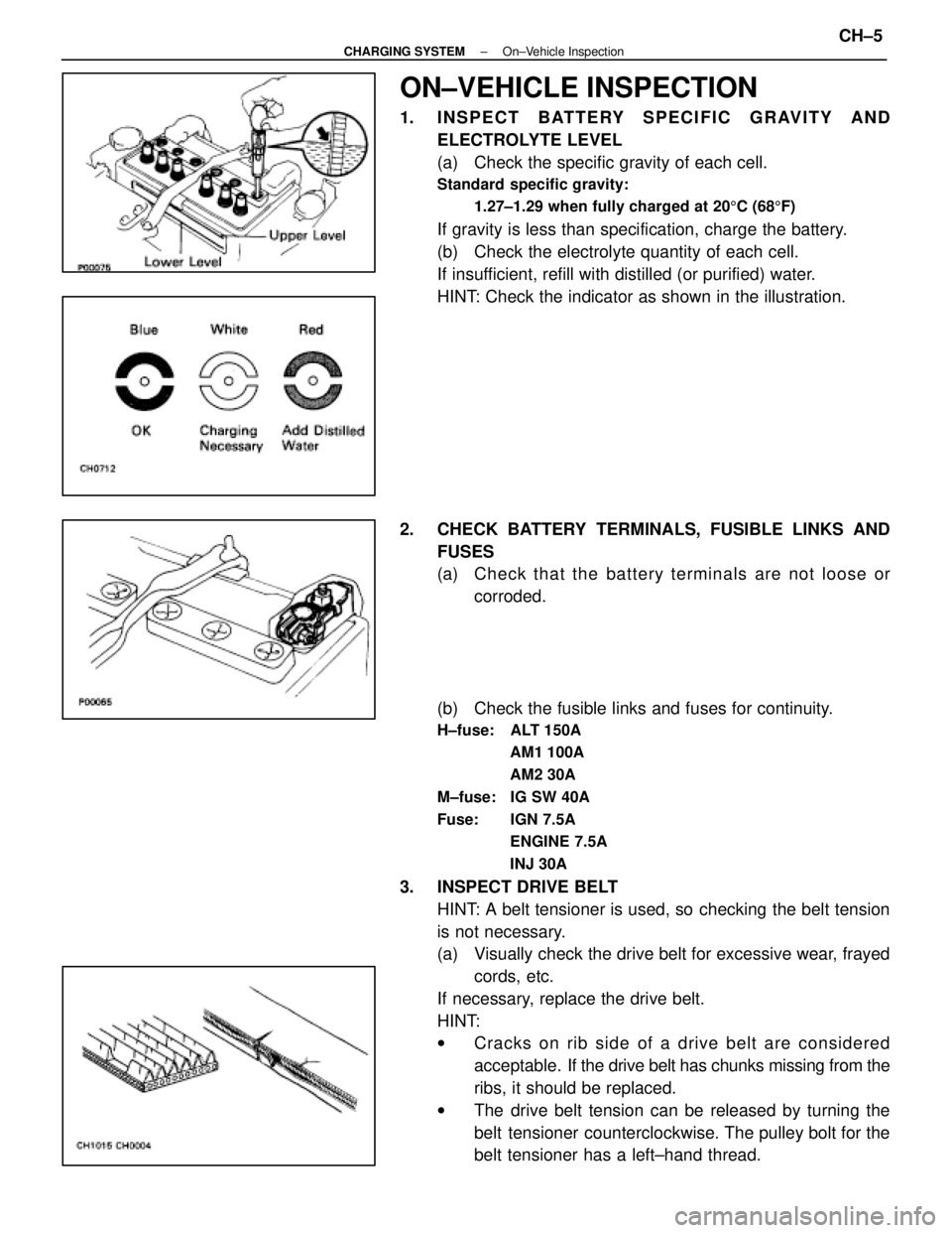
ON±VEHICLE INSPECTION
1. INSPECT BATTERY SPECIFIC GRAVITY ANDELECTROLYTE LEVEL
(a) Check the specific gravity of each cell.
Standard specific gravity:
1.27±1.29 when fully charged at 20 5C (68 5F)
If gravity is less than specification, charge the battery.
(b) Check the electrolyte quantity of each cell.
If insufficient, refill with distilled (or purified) water.
HINT: Check the indicator as shown in the illustration.
2. CHECK BATTERY TERMINALS, FUSIBLE LINKS AND FUSES
(a) Check that the battery terminals are not loose orcorroded.
(b) Check the fusible links and fuses for continuity.
H±fuse: ALT 150A AM1 100A
AM2 30A
M±fuse: IG SW 40A
Fuse: IGN 7.5A ENGINE 7.5A
INJ 30A
3. INSPECT DRIVE BELTHINT: A belt tensioner is used, so checking the belt tension
is not necessary.
(a) Visually check the drive belt for excessive wear, frayedcords, etc.
If necessary, replace the drive belt.
HINT:
w Cracks on rib side of a drive belt are considered
acceptable. If the drive belt has chunks missing from the
ribs, it should be replaced.
w The drive belt tension can be released by turning the
belt tensioner counterclockwise. The pulley bolt for the
belt tensioner has a left±hand thread.
±
CHARGING SYSTEM On±Vehicle InspectionCH±5
WhereEverybodyKnowsYourName