Page 2807 of 4087
9. FILL ENGINE WITH COOLANT (See page CO±7)
10. FILL COOLING FAN RESERVOIR TANK WITH FLUID (See pages CO±23 and 24)
11. CHECK AUTOMATIC TRANSMISSION FLUID LEVEL
(See page MA±11)
NOTICE: Do not overfill.
12. START ENGINE AND CHECK FOR LEAKS
13. INSTALL ENGINE UNDER COVER
±
COOLIING SYSTEM RadiatorCO±21
WhereEverybodyKnowsYourName
Page 2808 of 4087
ELECTRONICALLY CONTROLLED HYDRAULIC COOLING FAN
Description
In this way system, the cooling fan ECU controls the hydraulic pressure ac\
ting on the hydraulic motor, thus
controlling the speed of the cooling fan steplessly in response to the c\
ondition of the engine and air conditioner.
Operation
The hydraulic pump is driven by a drive belt (V±ribbed belt). The sole\
noid valve adjusts the volume of oil
sent from the hydraulic pump to the hydraulic motor which drives the fan dir\
ectly, thereby controlling the fan
speed. Oil which has passed through the hydraulic motor is cooled by the oil coole\
r before returning to the reservoir
tank. The solenoid valve is controlled by the computer in accordance with the E/G\
rpm, water temp. and A/C
signals. CO±22
±
COOLIING SYSTEM Electronically Controlled Hydraulic
Cooling Fan (Description, Operation)
WhereEverybodyKnowsYourName
Page 2809 of 4087

On±Vehicle Inspection
INSPECTION OF DRIVE BELT
(See step 1 on page CH±5)
INSPECTION OF FLUID LEVEL
1. KEEP VEHICLE LEVEL
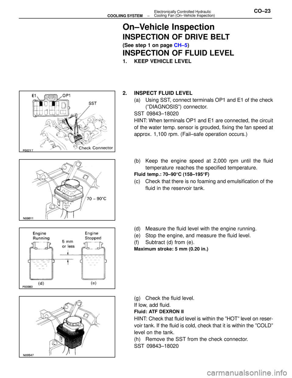
2. INSPECT FLUID LEVEL
(a) Using SST, connect terminals OP1 and E1 of the check(ºDIAGNOSISº) connector.
SST 09843±18020
HINT: When terminals OP1 and E1 are connected, the circuit
of the water temp. sensor is grouded, fixing the fan speed at
approx. 1,100 rpm. (Fail±safe operation occurs.)
(b) Keep the engine speed at 2,000 rpm until the fluid temperature reaches the specified temperature.
Fluid temp.: 70±90 5C (158±195 5F)
(c) Check that there is no foaming and emulsification of the
fluid in the reservoir tank.
(d) Measure the fluid level with the engine running.
(e) Stop the engine, and measure the fluid level.
(f) Subtract (d) from (e).
Maximum stroke: 5 mm (0.20 in.)
(g) Check the fluid level.
If low, add fluid.
Fluid: ATF DEXRON II
HINT: Check that fluid level is within the ºHOTº level on reser-
voir tank. If the fluid is cold, check that it is within the ºCOLDº\
level on the tank.
(h) Remove the SST from the check connector.
SST 09843±18020
±
COOLIING SYSTEM Electronically Controlled Hydraulic
Cooling Fan (On±Vehicle Inspection)CO±23
WhereEverybodyKnowsYourName
Page 2810 of 4087

BLEEDING OF HYDRAULIC COOLING
SYSTEM
1. CHECK FLUID LEVEL IN RESERVOIR TANKIf low, add fluid.
Fluid: ATF DEXRON II
HINT: Check that fluid level is within the ºHOTº level on reser-
voir tank. If the fluid is cold, check that it is within the ºCOLDº\
level on the tank.
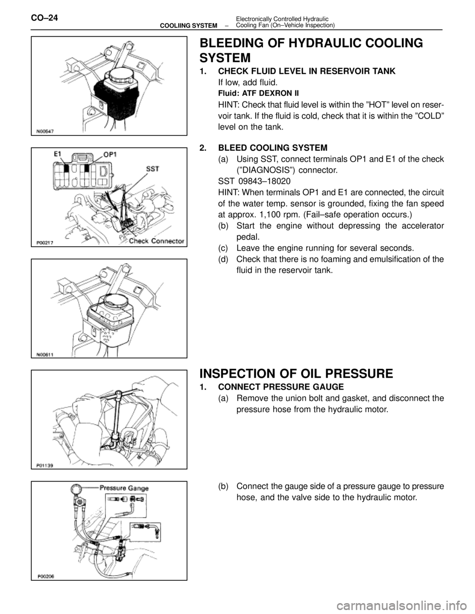
2. BLEED COOLING SYSTEM (a) Using SST, connect terminals OP1 and E1 of the check(ºDIAGNOSISº) connector.
SST 09843±18020
HINT: When terminals OP1 and E1 are connected, the circuit
of the water temp. sensor is grounded, fixing the fan speed
at approx. 1,100 rpm. (Fail±safe operation occurs.)
(b) Start the engine without depressing the accelerator pedal.
(c) Leave the engine running for several seconds.
(d) Check that there is no foaming and emulsification of the fluid in the reservoir tank.
INSPECTION OF OIL PRESSURE
1. CONNECT PRESSURE GAUGE
(a) Remove the union bolt and gasket, and disconnect thepressure hose from the hydraulic motor.
(b) Connect the gauge side of a pressure gauge to pressure
hose, and the valve side to the hydraulic motor.
CO±24
±
COOLIING SYSTEM Electronically Controlled Hydraulic
Cooling Fan (On±Vehicle Inspection)
WhereEverybodyKnowsYourName
Page 2811 of 4087

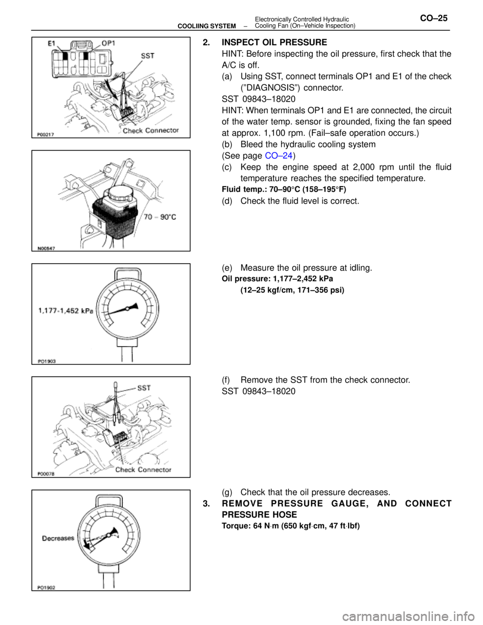
2. INSPECT OIL PRESSUREHINT: Before inspecting the oil pressure, first check that the
A/C is off.
(a) Using SST, connect terminals OP1 and E1 of the check(ºDIAGNOSISº) connector.
SST 09843±18020
HINT: When terminals OP1 and E1 are connected, the circuit
of the water temp. sensor is grounded, fixing the fan speed
at approx. 1,100 rpm. (Fail±safe operation occurs.)
(b) Bleed the hydraulic cooling system
(See page CO±24)
(c) Keep the engine speed at 2,000 rpm until the fluid temperature reaches the specified temperature.
Fluid temp.: 70±90 5C (158±195 5F)
(d) Check the fluid level is correct.
(e) Measure the oil pressure at idling.
Oil pressure: 1,177±2,452 kPa
(12±25 kgf/cm, 171±356 psi)
(f) Remove the SST from the check connector.
SST 09843±18020
(g) Check that the oil pressure decreases.
3. REMOVE PRESSURE GAUGE, AND CONNECT PRESSURE HOSE
Torque: 64 N Vm (650 kgf Vcm, 47 ft Vlbf)
±
COOLIING SYSTEM Electronically Controlled Hydraulic
Cooling Fan (On±Vehicle Inspection)CO±25
WhereEverybodyKnowsYourName
Page 2813 of 4087

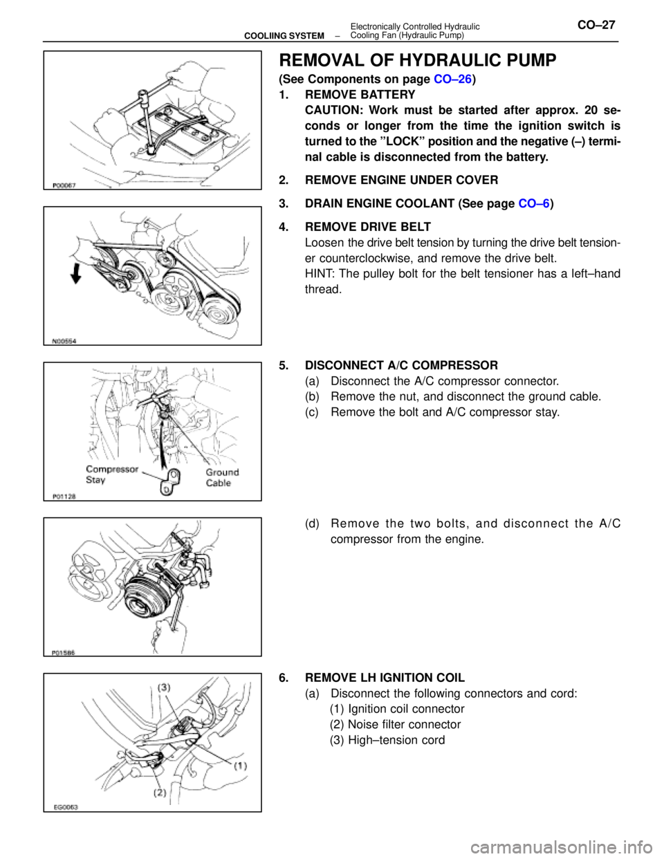
REMOVAL OF HYDRAULIC PUMP
(See Components on page CO±26)
1. REMOVE BATTERY CAUTION: Work must be started after approx. 20 se-
conds or longer from the time the ignition switch is
turned to the ºLOCKº position and the negative (±) termi-
nal cable is disconnected from the battery.
2. REMOVE ENGINE UNDER COVER
3. DRAIN ENGINE COOLANT (See page CO±6)
4. REMOVE DRIVE BELT Loosen the drive belt tension by turning the drive belt tension-
er counterclockwise, and remove the drive belt.
HINT: The pulley bolt for the belt tensioner has a left±hand
thread.
5. DISCONNECT A/C COMPRESSOR (a) Disconnect the A/C compressor connector.
(b) Remove the nut, and disconnect the ground cable.
(c) Remove the bolt and A/C compressor stay.
(d) R e m o v e t h e t w o b o l t s , a n d d i s c onnect the A/C
compressor from the engine.
6. REMOVE LH IGNITION COIL (a) Disconnect the following connectors and cord:(1) Ignition coil connector
(2) Noise filter connector
(3) High±tension cord
±
COOLIING SYSTEM Electronically Controlled Hydraulic
Cooling Fan (Hydraulic Pump)CO±27
WhereEverybodyKnowsYourName
Page 2814 of 4087
(b) Remove the two bolts and ignition coil.
7. REMOVE INTAKE AIR CONNECTOR (a) Disconnect the following hoses:(1) Air hose from ISC valve
(2) Air hose (from PS air control valve) from intake air
connector
(b) Remove the bolt holding the intake air connector to the cylinder head cover.
(c) Loosen the two hose clamps.
(d) Disconnect the intake air connector from the throttle
body and air cleaner hose, and remove the throttle body.
8. REMOVE UPPER HIGH±TENSION CORD COVER (a) Remove the two mounting bolts.
(b) Disconnect the front side claw groove of the cord coverfrom the claw of the lower cover, and remove the cord
cover.
9. REMOVE RH ENGINE WIRE COVER Remove the bolt and engine wire cover.
CO±28
±
COOLIING SYSTEM Electronically Controlled Hydraulic
Cooling Fan (Hydraulic Pump)
WhereEverybodyKnowsYourName
Page 2815 of 4087
10. REMOVE LH ENGINE WIRE COVERRemove the two bolts and engine wire cover.
11. REMOVE VSV FOR EVAP SYSTEM Remove the two bolts, and disconnect the VSV from cylinder
head and timing belt cover.
12. REMOVE RH NO.3 TIMING BELT COVER Remove the three bolts and timing belt cover.
13. REMOVE LH NO.3 TIMING BELT COVER (a) Remove the four mounting bolts.
(b) Disconnect the cord grommet from the timing belt cover,
and remove the timing belt cover.
(c) Remove the cord grommet from the high±tension cord.
14. DISCONNECT RADIATOR HOSE FROM WATER INLET
15. REMOVE DRIVE BELT IDLER PULLEY Remove the pulley bolt, cover plate and idler pulley.
±
COOLIING SYSTEM Electronically Controlled Hydraulic
Cooling Fan (Hydraulic Pump)CO±29
WhereEverybodyKnowsYourName