Page 2848 of 4087
(Water Temperature Sensor)
COMPONENTS FOR REMOVAL AND
INSTALLATION
INSPECTION OF WATER TEMPERATURE
SENSOR
1. DISCONNECT CABLE FROM NEGATIVE TERMINAL OFBATTERY
CAUTION: Work must be started after 20 seconds or
longer from the time the ignition switch is turned to the
ºLOCKº position and the negative (±) terminal cable is
disconnected from the battery.
2. REMOVE ENGINE UNDER COVER
3. DRAIN ENGINE COOLANT (See page CO±6)
4. REMOVE WATER TEMPERATURE SENSOR (a) Disconnect the water temperature sensor connector.
(b) Remove the water temperature sensor from left side ofthe radiator lower tank.
(c) Remove the O±ring from the water temperature sensor.
CO±62
±
COOLIING SYSTEM Electronically Controlled Hydraulic
Cooling Fan (Electronic Control Parts)
WhereEverybodyKnowsYourName
Page 2849 of 4087

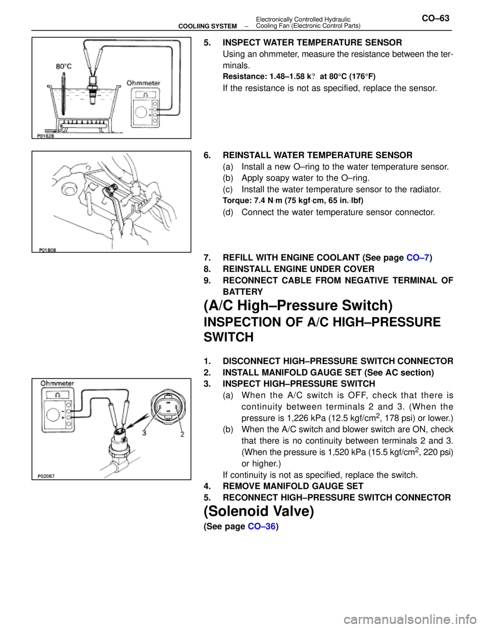
5. INSPECT WATER TEMPERATURE SENSORUsing an ohmmeter, measure the resistance between the ter-
minals.
Resistance: 1.48±1.58 k � at 80 5C (176 5F)
If the resistance is not as specified, replace the sensor.
6. REINSTALL WATER TEMPERATURE SENSOR (a) Install a new O±ring to the water temperature sensor.
(b) Apply soapy water to the O±ring.
(c) Install the water temperature sensor to the radiator.
Torque: 7.4 N Vm (75 kgf Vcm, 65 in. Vlbf)
(d) Connect the water temperature sensor connector.
7. REFILL WITH ENGINE COOLANT (See page CO±7)
8. REINSTALL ENGINE UNDER COVER
9. RECONNECT CABLE FROM NEGATIVE TERMINAL OF BATTERY
(A/C High±Pressure Switch)
INSPECTION OF A/C HIGH±PRESSURE
SWITCH
1. DISCONNECT HIGH±PRESSURE SWITCH CONNECTOR
2. INSTALL MANIFOLD GAUGE SET (See AC section)
3. INSPECT HIGH±PRESSURE SWITCH(a) Wh e n th e A/C switch is OFF, ch e ck th a t th e re iscontinuity between terminals 2 and 3. (When the
pressure is 1,226 kPa (12.5 kgf/cm
2, 178 psi) or lower.)
(b) When the A/C switch and blower switch are ON, check
that there is no continuity between terminals 2 and 3.
(When the pressure is 1,520 kPa (15.5 kgf/cm
2, 220 psi)
or higher.)
If continuity is not as specified, replace the switch.
4. REMOVE MANIFOLD GAUGE SET
5. RECONNECT HIGH±PRESSURE SWITCH CONNECTOR
(Solenoid Valve)
(See page CO±36)
±
COOLIING SYSTEM Electronically Controlled Hydraulic
Cooling Fan (Electronic Control Parts)CO±63
WhereEverybodyKnowsYourName
Page 2851 of 4087

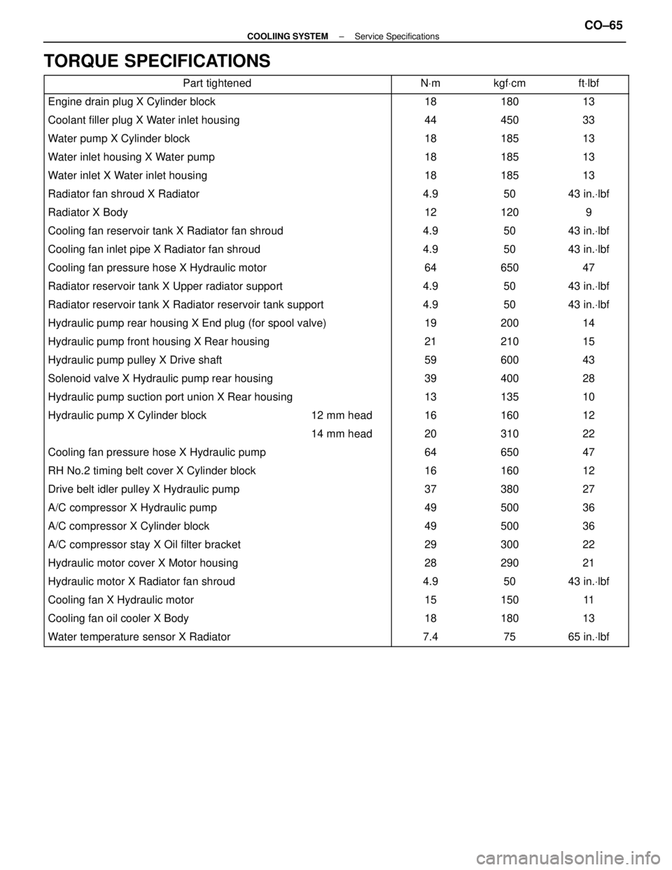
TORQUE SPECIFICATIONS
Part tightenedNVmkgf Vcmft Vlbf
Engine drain plug X Cylinder block1818013
Coolant filler plug X Water inlet housing44450 33
Water pump X Cylinder block18185 13
Water inlet housing X Water pump18185 13
Water inlet X Water inlet housing18185 13
Radiator fan shroud X Radiator4.950 43 in. Vlbf
Radiator X Body12120 9
Cooling fan reservoir tank X Radiator fan shroud4.950 43 in. Vlbf
Cooling fan inlet pipe X Radiator fan shroud4.950 43 in. Vlbf
Cooling fan pressure hose X Hydraulic motor64650 47
Radiator reservoir tank X Upper radiator support4.950 43 in. Vlbf
Radiator reservoir tank X Radiator reservoir tank support4.950 43 in. Vlbf
Hydraulic pump rear housing X End plug (for spool valve)19200 14
Hydraulic pump front housing X Rear housing21210 15
Hydraulic pump pulley X Drive shaft59600 43
Solenoid valve X Hydraulic pump rear housing39400 28
Hydraulic pump suction port union X Rear housing13135 10
����������������� �����������������Hydraulic pump X Cylinder block������ ������12 mm head����� �����16������ ������160������ ������12
����������������� ����������������������� ������14 mm head����� �����20������ ������310������ ������22
������������������\
���� ������������������\
����Cooling fan pressure hose X Hydraulic pump����� �����64������ ������650������ ������47
������������������\
���� ������������������\
����RH No.2 timing belt cover X Cylinder block����� �����16������ ������160������ ������12
������������������\
���� ������������������\
����Drive belt idler pulley X Hydraulic pump����� �����37������ ������380������ ������27
������������������\
���� ������������������\
����A/C compressor X Hydraulic pump����� �����49������ ������500������ ������36
������������������\
���� ������������������\
����A/C compressor X Cylinder block����� �����49������ ������500������ ������36������������������\
���� ������������������\
����A/C compressor stay X Oil filter bracket����� �����29������ ������300������ ������22������������������\
���� ������������������\
����Hydraulic motor cover X Motor housing����� �����28������ ������290������ ������21������������������\
���� �
������������������\
���
������������������\
����Hydraulic motor X Radiator fan shroud
����� �
����
�����4.9
������ �
�����
������50
������ �
�����
������43 in.
Vlbf
������������������\
���� ������������������\
����Cooling fan X Hydraulic motor����� �����15������ ������150������ ������11
������������������\
���� ������������������\
����Cooling fan oil cooler X Body����� �����18������ ������180������ ������13
������������������\
���� ������������������\
����Water temperature sensor X Radiator����� �����7.4������ ������75������ ������65 in. Vlbf
±
COOLIING SYSTEM Service SpecificationsCO±65
WhereEverybodyKnowsYourName
Page 2853 of 4087

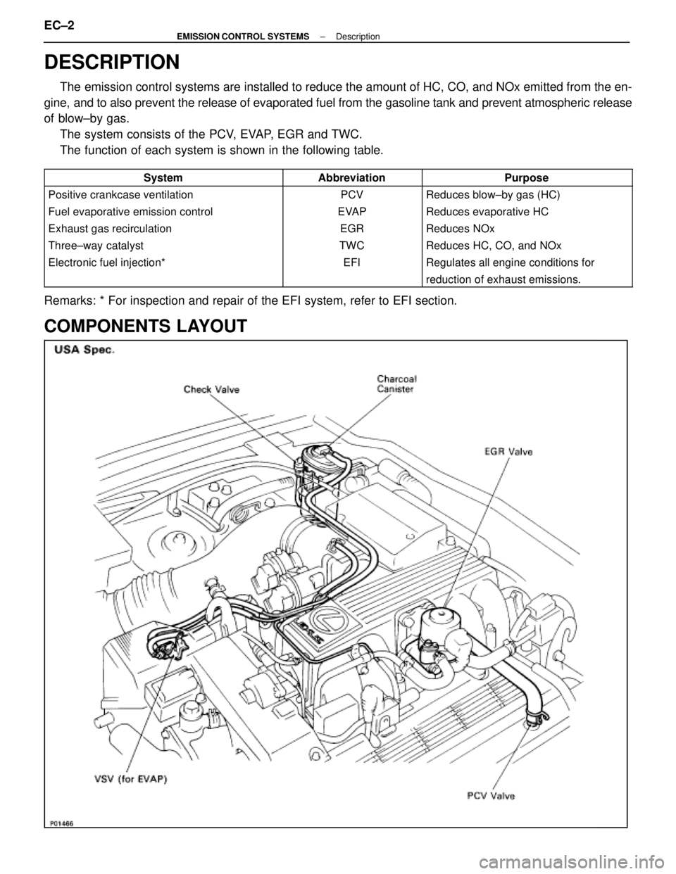
DESCRIPTION
The emission control systems are installed to reduce the amount of HC, CO, \
and NOx emitted from the en-
gine, and to also prevent the release of evaporated fuel from the gasoline ta\
nk and prevent atmospheric release
of blow±by gas. The system consists of the PCV, EVAP, EGR and TWC.
The function of each system is shown in the following table.
��������������� ���������������
System
��������� ���������
Abbreviation
�������������� ��������������
Purpose��������������� ���������������
Positive crankcase ventilation
��������� ���������
PCV
�������������� ��������������
Reduces blow±by gas (HC)��������������� ���������������
Fuel evaporative emission control
��������� ���������
EVAP
�������������� ��������������
Reduces evaporative HC��������������� ���������������
Exhaust gas recirculation
��������� ���������
EGR
�������������� ��������������
Reduces NOx��������������� ���������������
Three±way catalyst
��������� ���������
TWC
�������������� ��������������
Reduces HC, CO, and NOx��������������� ���������������
Electronic fuel injection*
��������� ���������
EFI
�������������� ��������������
Regulates all engine conditions for��������������� ������������������������ ����������������������� ��������������
reduction of exhaust emissions.
Remarks: * For inspection and repair of the EFI system, refer to EFI sec\
tion.
COMPONENTS LAYOUT
EC±2±
EMISSION CONTROL SYSTEMS Description
WhereEverybodyKnowsYourName
Page 2856 of 4087
PREPARATION
SST (SPECIAL SERVICE TOOL)
RECOMMENDED TOOLS
EQUIPMENT
Part NameNote
Engine tune±up testerEngine speed
±
EMISSION CONTROL SYSTEMS PreparationEC±5
WhereEverybodyKnowsYourName
Page 2866 of 4087
EXHAUST GAS RECIRCULATION (EGR) SYSTEM
DESCRIPTION
To reduce NOx emission, part of the exhaust gases are recirculated through\
the EGR valve to the intake
manifold to lower the maximum combustion temperature.
OPERATION
Coolant Temp.ConditionEGR ValveExhaust Gas
Below 53 5C (127 5F)±CLOSEDNot recirculated
Above 55 5C (131 5F)(a)Idling, Deceleration, Neutral,
Low air volume, High Engine speedCLOSEDNot recirculatedAbove 55 C (131 F)
Except (a)OPEN*Recirculated
* The ECU calculates the appropriate number of steps according to the in\
take air volume and the engine speed, then
drives the stepping motor to maintain the EGR volume at a level appropri\
ate to the driving conditions.
±
EMISSION CONTROL SYSTEMS Exhaust Gas Recirculation (EGR) SystemEC±15
WhereEverybodyKnowsYourName
Page 2868 of 4087
INSPECTION OF EGR SYSTEM (USA
Spec.)
INSPECT SYSTEM OPERATION
(a) Using SST, connect terminals TE1 and E1 of the check(ºDIAGNOSISº) connector.
SST 09843±18020
(b) Keep the engine at 3,500 rpm.
(c) Set the transmission shift lever to the ºNº position.
(d) Remove the SST from the check connector.
SST 09843±18020
(e) Check whether the engine rpm increases 100±300 rpm under the following conditions.
Coolant temp.
Below 53 5C (127 5F) No increase
Above 55 5C (131 5F) Increases
±
EMISSION CONTROL SYSTEMS Exhaust Gas Recirculation (EGR) SystemEC±17
WhereEverybodyKnowsYourName
Page 2869 of 4087
INSPECTION OF EGR SYSTEM
(Exc. USA Spec.)
1. CHECK AND CLEAN FILTERS IN EGR VACUUMMODULATOR
(a) Remove the cap and filter.
(b) Check the filter for contamination or damage.
(c) Using compressed air, clean the filters.
(d) Reinstall the filter and cap.
HINT: Install the filter with the coarser surface facing the at-
mospheric side (outward).
2. INSPECT SYSTEM OPERATION (a) Using SST, connect terminals TE1 and E1 of the check
(ºDIAGNOSISº) connector.
SST 09843±18020
(b) Keep the engine at 3,500 rpm.
(c) Set the transmission shift lever to the ºNº position.
(d) Remove the SST from the check connector.
SST 09843±18020
(e) Check whether the engine rpm increases 100±300 rpm under the following conditions:
Coolant temp.
Below 53 5C (127 5F) No increase
Above 55 5C (131 5F) Increases
EC±18
±
EMISSION CONTROL SYSTEMS Exhaust Gas Recirculation (EGR) System
WhereEverybodyKnowsYourName