Page 2394 of 4087
Preparation
SST (SPECIAL SERVICE TOOLS)
IllustrationPart No.Part NameNote
09268±41045Injection Measuring
Tool Set
(90268±41070)No. 4 Union
Injector
(09268±41080)No. 6 Union
Cold start Injector
(09268±52010)Injection Measuring
Attachment
Injector
09268±45012EFI Fuel Pressure
Gauge
09612±24014
Steering Gear
Housing Overhaul
Tool Set
(09617±24011)Steering Rack Wrench
Fuel pressure pulsation damper
09631±22020
Power Steering
Hose Nut 14 X 17 mm
Wrench SetFuel line flare nut
09816±30010Oil Pressure
Switch SocketKnock sensor
09842±30055Wire ªGº
EFI Inspection
Cold start Injector
09842±30070Wire ªFº
EFI Inspection
Injector
09843±18020Diagnosis Check
Wire
0990±01000
Engine Control
Computer
Check Harness ªAº
FI±10 ± PreparationEFI SYSTEM
WhereEverybodyKnowsYourName
Page 2397 of 4087
FUEL SYSTEM
Fuel Pump
ON±VEHICLE INSPECTION
1. CHECK FUEL PUMP OPERATION(a) Using SST, connect terminals +B and FP of the check
(ºDIAGNOSISº) connector.
SST 09843±18020
(b) Turn the ignition switch ON.
NOTICE: Do not start the engine.
(c) Check that there is pressure in the fuel inlet hose from the fuel filter.
HINT: At this time, you will hear fuel return noise.
(d) Turn the ignition switch OFF.
(e) Remove SST from the check connector.
SST 09843±18020 FI±17
± Fuel System (Fuel Pump)EFI SYSTEM
WhereEverybodyKnowsYourName
Page 2398 of 4087

If there is no pressure, check the following parts:w Fuses
w EFI main relay
w Fuel pump ECU
w Fuel pump
w Engine & ECT ECU
w Wiring connections
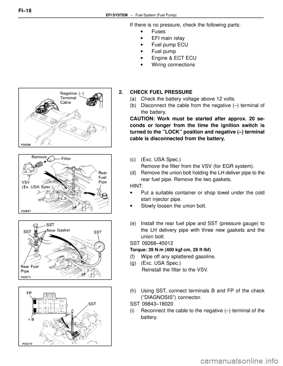
2. CHECK FUEL PRESSURE (a) Check the battery voltage above 12 volts.
(b) Disconnect the cable from the negative (±) terminal ofthe battery.
CAUTION: Work must be started after approx. 20 se-
conds or longer from the time the ignition switch is
turned to the ºLOCKº position and negative (±) terminal
cable is disconnected from the battery.
(c) (Exc. USA Spec.) Remove the filter from the VSV (for EGR system).
(d) Remove the union bolt holding the LH deliver pipe to the
rear fuel pipe. Remove the two gaskets.
HINT:
w Put a suitable container or shop towel under the cold
start injector pipe.
w Slowly loosen the union bolt.
(e) Install the rear fuel pipe and SST (pressure gauge) to the LH delivery pipe with three new gaskets and the
union bolt.
SST 09268±45012
Torque: 39 N Vm (400 kgf Vcm, 29 ft Vlbf)
(f) Wipe off any splattered gasoline.
(g) (Exc. USA Spec.)
Reinstall the filter to the VSV.
(h) Using SST, connect terminals B and FP of the check (ºDIAGNOSISº) connector.
SST 09843±18020
(i) Reconnect the cable to the negative (±) terminal of the
battery.
FI±18
EFI SYSTEM
± Fuel System (Fuel Pump)
WhereEverybodyKnowsYourName
Page 2399 of 4087

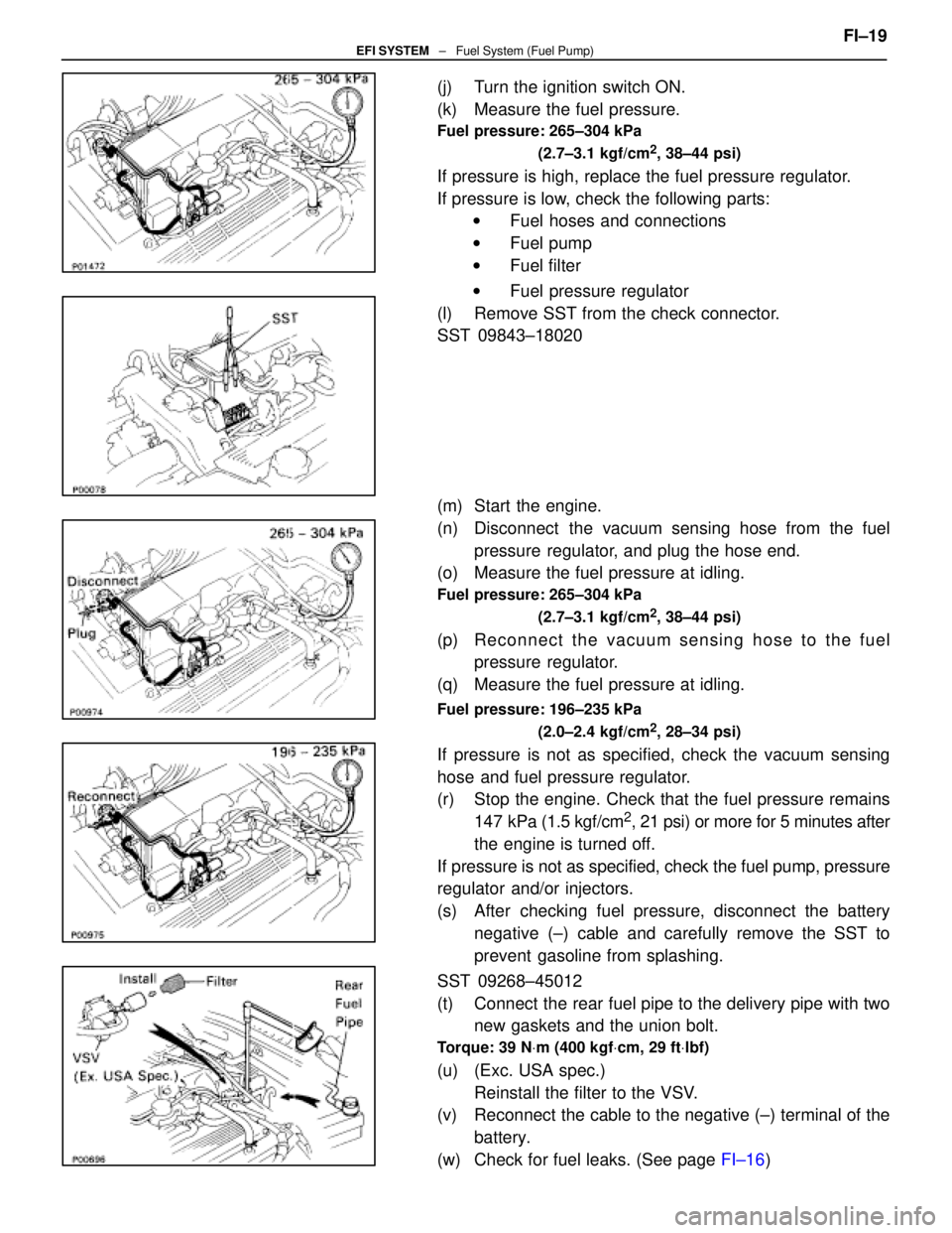
(j) Turn the ignition switch ON.
(k) Measure the fuel pressure.
Fuel pressure: 265±304 kPa(2.7±3.1 kgf/cm
2, 38±44 psi)
If pressure is high, replace the fuel pressure regulator.
If pressure is low, check the following parts:w Fuel hoses and connections
w Fuel pump
w Fuel filter
w Fuel pressure regulator
(l) Remove SST from the check connector.
SST 09843±18020
(m) Start the engine.
(n) Disconnect the vacuum sensing hose from the fuel pressure regulator, and plug the hose end.
(o) Measure the fuel pressure at idling.
Fuel pressure: 265±304 kPa
(2.7±3.1 kgf/cm
2, 38±44 psi)
(p) Re connect the vacuum sensing hose to the fuel
pressure regulator.
(q) Measure the fuel pressure at idling.
Fuel pressure: 196±235 kPa
(2.0±2.4 kgf/cm
2, 28±34 psi)
If pressure is not as specified, check the vacuum sensing
hose and fuel pressure regulator.
(r) Stop the engine. Check that the fuel pressure remains147 kPa (1.5 kgf/cm
2, 21 psi) or more for 5 minutes after
the engine is turned off.
If pressure is not as specified, check the fuel pump, pressure
regulator and/or injectors.
(s) After checking fuel pressure, disconnect the battery negative (±) cable and carefully remove the SST to
prevent gasoline from splashing.
SST 09268±45012
(t) Connect the rear fuel pipe to the delivery pipe with two new gaskets and the union bolt.
Torque: 39 N Vm (400 kgf Vcm, 29 ft Vlbf)
(u) (Exc. USA spec.)
Reinstall the filter to the VSV.
(v) Reconnect the cable to the negative (±) terminal of the
battery.
(w) Check for fuel leaks. (See page FI±16) FI±19
EFI SYSTEM
± Fuel System (Fuel Pump)
WhereEverybodyKnowsYourName
Page 2410 of 4087
(2) Water by±pass hose from ISC valve
(3) (USA Spec.)Vacuum hose
(4) (Exc. USA Spec.) Three vacuum hoses
(c) Remove the two bolts and two nuts, disconnect the throttle body from the air intake chamber.
(d) Disconnect the following hoses, and remove the throttle body:
(1) PCV hose from throttle body
(2) Water by±pass hose from throttle body
(e) Remove the throttle body gasket.
14. DISCONNECT CONNECTORS Disconnect the following connectors:w Cold start injector connector
w ISC valve connector
w (USA Spec.)
EGR valve connector for EGR system
w (Exc. USA Spec.)
VSV connector for EGR
w VSV connector for fuel pressure control system
FI±30
EFI SYSTEM
± Fuel System (Cold Start Injector)
WhereEverybodyKnowsYourName
Page 2411 of 4087
15. DISCONNECT HOSESDisconnect the following hoses:(1) Water by±pass hose (from water inlet housing) from ISC valve
(2) Vacuum hose (from PS air control valve) from air in-
take chamber
(3) Vacuum sensing hose (from fuel pressure regula- tor) from vacuum pipe
(4) Two vacuum hoses (from VSV for EVAP system) from vacuum pipe
(5) Vacuum hose (from charcoal canister) from vacu- um pipe
(6) Water by±pass hose (from EGR valve) from water by±pass pipe
(7) Vacuum hose (from brake booster) from air intake
chamber
(8) Vacuum hose (from VSV for heater water valve) from air intake chamber
(9) PCV hose from LH cylinder head cover
16. REMOVE AIR INTAKE CHAMBER (a) Remove the bolt, stud bolt and accelerator bracket. FI±31
EFI SYSTEM
± Fuel System (Cold Start Injector)
WhereEverybodyKnowsYourName
Page 2416 of 4087
(b) Temporarily install a new gasket and the EGR pipe to air
intake chamber with the two bolt.
(c) (Exc. USA Spec.) Install the connector bracket to check (ºDIAGNOSISº)
connector.
(d) Install the air intake chamber and following parts with the four bolts and eight nuts:
(1) Check (ºDIAGNOSISº) connector
(2) A/T throttle cable bracket
(3) VSV for fuel pressure control system
(4) VSV for EGR system
Torque: 18 N Vm (185 kgf Vcm, 13 ft Vlbf)
HINT: Use bolts 40 mm (1.57 in.) of length.
(e) Tighten the bolt holding the EGR pipe to the air intake
chamber.
Torque: 18 N Vm (185 kgf Vcm, 13 ft Vlbf)
(f) Connect the cold start injector tube to the RH delivery
pipe with two new gaskets and union bolt.
Torque: 15 N Vm (150 kgf Vcm, 11 ft Vlbf)
FI±36EFI SYSTEM ± Fuel System (Cold Start Injector)
WhereEverybodyKnowsYourName
Page 2417 of 4087
(g) Install the accelerator bracket with the bolt and stud bolt.
3. CONNECT HOSES Connect the following hoses:(1) Water by±pass hose (from EGR valve) to water by±
pass pipe
(2) Vacuum hose (from brake booster) to air intake chamber
(3) Vacuum hose (from VSV for heater water valve) to
air intake chamber
(4) PCV hose to LH cylinder head cover
(5) Water by±pass hose (from water inlet housing) to ISC valve
(6) Vacuum hose (from PS air control valve) to air in- take chamber
(7) Vacuum sensing hose (from fuel pressure regula- tor) to vacuum pipe
(8) Two vacuum hoses (from VSV for EVAP system) to
vacuum pipe
(9) Vacuum hose (from charcoal canister) to vacuum pipe FI±37
EFI SYSTEM
± Fuel System (Cold Start Injector)
WhereEverybodyKnowsYourName