Page 2071 of 4087
5. INSTALL AIR INTAKE CHAMBER STAYSInstall the intake chamber stay with the bolt and nut.
Install the No. 1 and No. 2 stays.
Torque: 18 N Vm (185 kgf Vcm, 13 ft Vlbf)
HINT: The No. 1 stay is marked ºFº and No. 2 stay is marked
with ºRº.
6. CONNECT NO. 2 FUEL PIPE TO FUEL PRESSURE REGULATOR
Connect the fuel pipe with two new gaskets and the union
bolt.
Torque: 27 N Vm (280 kgf Vcm, 20 ft Vlbf)
7. CONNECT NO. 1 FUEL PIPE TO DELIVERY PIPE
Connect the fuel pipe with two new gaskets and the union
bolt.
Torque: 42 N Vm (420 kgf Vcm, 30 ft Vlbf)
8. INSTALL THROTTLE BODY WITH INTAKE AIR
CONNECTOR
(See steps 16 to 20 on pages EM±18 and 19)
9. FILL WITH COOLANT (See page CO±5)
10. C O N N E C T C A B L E TO N E G AT I V E T E R M I N A L O F BATTERY
FI±34
±
EFI SYSTEM Fuel System (Injectors)
WhereEverybodyKnowsYourName
Page 2072 of 4087
Fuel Pressure Pulsation Damper
COMPONENTS FOR REMOVAL AND
INSTALLATION
REMOVAL OF FUEL PRESSURE
PULSATION DAMPER
1. (A/T)REMOVE DIPSTICK GUIDE FOR TRANSMISSION
(a) Remove the mounting bolt.
(b) P u l l o u t t h e d i s t i c k g u i d e a n d d i p s t i c k f r o m t h etransmission.
(c) Remove the O±ring from the dipstick guide.
2. REMOVE STARTER (See page ST±5)
3. REMOVE FUEL PRESSURE PULSATION DAMPER (a) Remove the pulsation damper and upper gasket.
(b) Disc onnect the No. 1 fuel pipe from the fuel pipe
support, and remove the lower gasket.
±
EFI SYSTEM Fuel System (Fuel Pressure Pulsation Damper)FI±35
WhereEverybodyKnowsYourName
Page 2073 of 4087
INSTALLATION OF FUEL PRESSURE
PULSATION DAMPER
(See Components on page FI±35)
1. INSTALL FUEL PRESSURE PULSATION DAMPER (a) In sta ll two ne w ga ske ts, th e No . 1 fu e l pip e an dpulsation damper.
(b) Using SST, torque the pulsation damper.
SST 09612±24014 (09617±24011)
Torque: 41 N Vm (420 kgf Vcm, 30 ft Vlbf)
35 N Vm (350 kgf Vcm, 25 ft Vlbf) for SST
HINT: Use a torque wrench with a fulcrum length of 30 cm
(11.81 in.).
2. INSTALL STARTER (See page ST±5)
Torque: 39 N Vm (400 kgf Vcm, 29 ft Vlbf)
3. (A/T)
INSTALL DIPSTICK GUIDE FOR TRANSMISSION
(a) Install a new O±ring to the dipstick guide.
(b) Apply soapy water to the O±ring.
(c) Connect the dipstick guide end to the tube of the oil pan,
and install the dipstick guide with the bolt.
(d) Install the dipstick.
4. CHECK FOR FUEL LEAKS (See page FI±15)
FI±36
±
EFI SYSTEM Fuel System (Fuel Pressure Pulsation Damper)
WhereEverybodyKnowsYourName
Page 2079 of 4087
Fuel Pressure Regulator
ON±VEHICLE INSPECTION
INSPECT FUEL PRESSURE (See page FI±18)
FI±42
± Fuel System (Fuel Pressure Regulator)EFI SYSTEM
WhereEverybodyKnowsYourName
Page 2080 of 4087
COMPONENTS FOR REMOVAL AND
INSTALLATION
REMOVAL OF FUEL PRESSURE
REGULATOR
1. DISCONNECT CABLE FROM NEGATIVE TERMINAL OFBATTERY
CAUTION: Work must be started after approx. 20 se-
conds or longer from the time the ignition switch is
turned to the ºLOCKº position and the negative (±) termi-
nal cable is disconnected from the battery.
2. REMOVE INTAKE AIR CONNECTOR (a) Disconnect the following hoses:(1) Air hose from ISC valve
(2) Air hose (from PS air control valve) from intake air
connector FI±43
EFI SYSTEM
± Fuel System (Fuel Pressure Regulator)
WhereEverybodyKnowsYourName
Page 2081 of 4087
(b) Remove the bolt holding the intake air connector to thecylinder head cover.
(c) Loosen the two hose clamps.
(d) Disconnect the intake air connector from the throttle
body and air cleaner hose, and remove the intake air
connector.
3. REMOVE UPPER HIGH±TENSION CORD COVER (a) Remove the two mounting bolts.
(b) Disconnect the front side claw groove of the cord cover
from the claw of the lower cover, and remove the cord
cover.
4. REMOVE RH ENGINE WIRE COVER Remove the bolt and wire cover.
5. DISCONNECT VACUUM SENSING HOSE FROM FUEL PRESSURE REGULATOR
FI±44
EFI SYSTEM
± Fuel System (Fuel Pressure Regulator)
WhereEverybodyKnowsYourName
Page 2082 of 4087

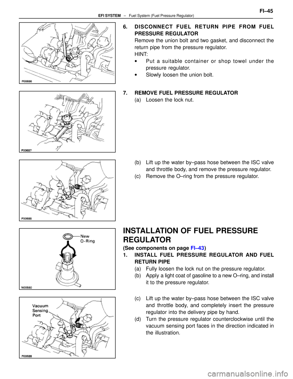
6. DISCONNECT FUEL RETURN PIPE FROM FUELPRESSURE REGULATOR
Remove the union bolt and two gasket, and disconnect the
return pipe from the pressure regulator.
HINT:
wPut a suitable container or shop towel under the
pressure regulator.
w Slowly loosen the union bolt.
7. REMOVE FUEL PRESSURE REGULATOR (a) Loosen the lock nut.
(b) Lift up the water by±pass hose between the ISC valveand throttle body, and remove the pressure regulator.
(c) Remove the O±ring from the pressure regulator.
INSTALLATION OF FUEL PRESSURE
REGULATOR
(See components on page FI±43)
1. INSTALL FUEL PRESSURE REGULATOR AND FUEL RETURN PIPE
(a) Fully loosen the lock nut on the pressure regulator.
(b) Apply a light coat of gasoline to a new O±ring, and install
it to the pressure regulator.
(c) Lift up the water by±pass hose between the ISC valve and throttle body, and completely insert the pressure
regulator into the delivery pipe by hand.
(d) Turn the pressure regulator counterclockwise until the vacuum sensing port faces in the direction indicated in
the illustration. FI±45
EFI SYSTEM
± Fuel System (Fuel Pressure Regulator)
WhereEverybodyKnowsYourName
Page 2083 of 4087
(e) Connect the fuel return pipe to the pressure regulatorwith new two gaskets and the union bolt.
Torque: 35 N Vm (360 kgf Vcm, 26 ft Vlbf)
(f) Tighten the lock nut.
Torque: 29 N Vm (300 kgf Vcm, 22 ft Vlb)
2. CONNECT VACUUM SENSING HOSE TO FUEL
PRESSURE REGULATOR
3. INSTALL RH ENGINE WIRE COVER (a) Fit portions A and B of the engine wire cover, matchingthem with the lower high±tension cord cover and No.3
timing belt cover.
(d) Install the engine wire cover with the bolt.
FI±46
EFI SYSTEM
± Fuel System (Fuel Pressure Regulator)
WhereEverybodyKnowsYourName