Page 2052 of 4087
15. DISCONNECT HOSESDisconnect the following hoses:(1) Water by±pass hose (from water inlet housing) from ISC valve
(2) Vacuum hose (from PS air control valve) from air in-
take chamber
(3) Vacuum sensing hose (from fuel pressure regula- tor) from vacuum pipe
(4) Two vacuum hoses (from VSV for EVAP system) from vacuum pipe
(5) Vacuum hose (from charcoal canister) from vacu- um pipe
(6) Water by±pass hose (from EGR valve) from water by±pass pipe
(7) Vacuum hose (from brake booster) from air intake
chamber
(8) Vacuum hose (from VSV for heater water valve) from air intake chamber
(9) PCV hose from LH cylinder head cover
16. REMOVE AIR INTAKE CHAMBER (a) Remove the bolt, stud bolt and accelerator bracket. FI±31
EFI SYSTEM
± Fuel System (Cold Start Injector)
WhereEverybodyKnowsYourName
Page 2057 of 4087
(b) Temporarily install a new gasket and the EGR pipe to air
intake chamber with the two bolt.
(c) (Exc. USA Spec.) Install the connector bracket to check (ºDIAGNOSISº)
connector.
(d) Install the air intake chamber and following parts with the four bolts and eight nuts:
(1) Check (ºDIAGNOSISº) connector
(2) A/T throttle cable bracket
(3) VSV for fuel pressure control system
(4) VSV for EGR system
Torque: 18 N Vm (185 kgf Vcm, 13 ft Vlbf)
HINT: Use bolts 40 mm (1.57 in.) of length.
(e) Tighten the bolt holding the EGR pipe to the air intake
chamber.
Torque: 18 N Vm (185 kgf Vcm, 13 ft Vlbf)
(f) Connect the cold start injector tube to the RH delivery
pipe with two new gaskets and union bolt.
Torque: 15 N Vm (150 kgf Vcm, 11 ft Vlbf)
FI±36EFI SYSTEM ± Fuel System (Cold Start Injector)
WhereEverybodyKnowsYourName
Page 2058 of 4087
(g) Install the accelerator bracket with the bolt and stud bolt.
3. CONNECT HOSES Connect the following hoses:(1) Water by±pass hose (from EGR valve) to water by±
pass pipe
(2) Vacuum hose (from brake booster) to air intake chamber
(3) Vacuum hose (from VSV for heater water valve) to
air intake chamber
(4) PCV hose to LH cylinder head cover
(5) Water by±pass hose (from water inlet housing) to ISC valve
(6) Vacuum hose (from PS air control valve) to air in- take chamber
(7) Vacuum sensing hose (from fuel pressure regula- tor) to vacuum pipe
(8) Two vacuum hoses (from VSV for EVAP system) to
vacuum pipe
(9) Vacuum hose (from charcoal canister) to vacuum pipe FI±37
EFI SYSTEM
± Fuel System (Cold Start Injector)
WhereEverybodyKnowsYourName
Page 2059 of 4087
4. CONNECT CONNECTORSConnect the following connectors:w Cold start injector connector
w ISC valve connector
w (USA Spec.)
EGR valve connector
w (Exc. USA Spec.)
VSV connector for EGR system
w SV connector for fuel pressure control system
5. INSTALL THROTTLE BODY (a) Connect the following hoses:(1) PCV hose to throttle body
(2) Water by±pass hose to throttle body
(b) Install a new gasket and throttle body with the two bolts and two nuts.
Torque: 18 N Vm (185 kgf Vcm, 13 ft Vlbf)
HINT: Use bolts 40 mm (1.57 in.) in length.
(c) Install the water by±pass pipe (from rear water bypass
joint) to the clamp on the engine wire cover.
(d) Connect the following hoses: (1) Water by±pass hose to the ISC valve
(2) (USA Spec.) Vacuum hose to throttle body
(3) (Exc. USA Spec.) Three vacuum hoses to throttle body
FI±38
EFI SYSTEM
± Fuel System (Cold Start Injector)
WhereEverybodyKnowsYourName
Page 2061 of 4087

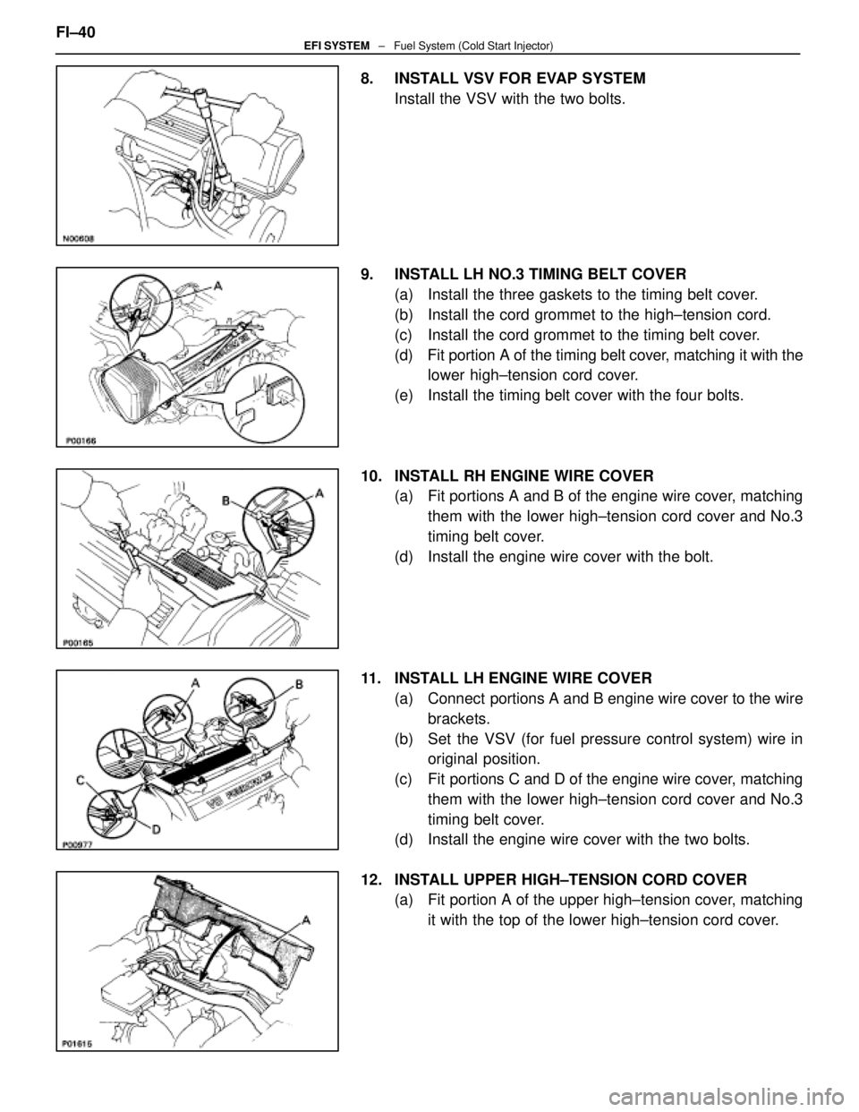
8. INSTALL VSV FOR EVAP SYSTEMInstall the VSV with the two bolts.
9. INSTALL LH NO.3 TIMING BELT COVER (a) Install the three gaskets to the timing belt cover.
(b) Install the cord grommet to the high±tension cord.
(c) Install the cord grommet to the timing belt cover.
(d) Fit portion A of the timing belt cover, matching it with the
lower high±tension cord cover.
(e) Install the timing belt cover with the four bolts.
10. INSTALL RH ENGINE WIRE COVER (a) Fit portions A and B of the engine wire cover, matching
them with the lower high±tension cord cover and No.3
timing belt cover.
(d) Install the engine wire cover with the bolt.
11. INSTALL LH ENGINE WIRE COVER (a) Connect portions A and B engine wire cover to the wirebrackets.
(b) Set the VSV (for fuel pressure control system) wire in original position.
(c) Fit portions C and D of the engine wire cover, matching them with the lower high±tension cord cover and No.3
timing belt cover.
(d) Install the engine wire cover with the two bolts.
12. INSTALL UPPER HIGH±TENSION CORD COVER (a) Fit portion A of the upper high±tension cover, matching
it with the top of the lower high±tension cord cover.
FI±40
EFI SYSTEM
± Fuel System (Cold Start Injector)
WhereEverybodyKnowsYourName
Page 2065 of 4087

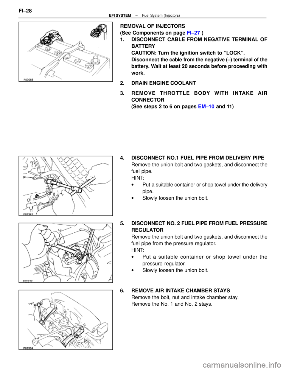
REMOVAL OF INJECTORS
(See Components on page FI±27 )
1. DISCONNECT CABLE FROM NEGATIVE TERMINAL OF
BATTERY
CAUTION: Turn the ignition switch to ºLOCKº.
Disconnect the cable from the negative (±) terminal of the
battery. Wait at least 20 seconds before proceeding with
work.
2. DRAIN ENGINE COOLANT
3. REMOVE THROTTLE BODY WITH INTAKE AIR CONNECTOR
(See steps 2 to 6 on pages EM±10 and 11)
4. DISCONNECT NO.1 FUEL PIPE FROM DELIVERY PIPE Remove the union bolt and two gaskets, and disconnect the
fuel pipe.
HINT:
wPut a suitable container or shop towel under the delivery
pipe.
w Slowly loosen the union bolt.
5. DISCONNECT NO. 2 FUEL PIPE FROM FUEL PRESSURE
REGULATOR
Remove the union bolt and two gaskets, and disconnect the
fuel pipe from the pressure regulator.
HINT:
w Put a suitable container or shop towel under the
pressure regulator.
w Slowly loosen the union bolt.
6. REMOVE AIR INTAKE CHAMBER STAYS Remove the bolt, nut and intake chamber stay.
Remove the No. 1 and No. 2 stays.
FI±28
±
EFI SYSTEM Fuel System (Injectors)
WhereEverybodyKnowsYourName
Page 2066 of 4087
7. DISCONNECT VACUUM SENSING HOSE FROMPRESSURE REGULATOR
8. DISCONNECT INJECTOR CONNECTORS
9. DISCONNECT CONTROL VALVE ACTUATOR
Remove the two bolts and turn the actuator sideways.
HINT: Wrap the actuator with adhesive tape and attach it to
the intake chamber.
NOTICE: Do not apply any force on the actuator rod and
prevent the rod clip from detaching.
10. REMOVE DELIVERY PIPE AND INJECTORS (a) Remove the three bolts and delivery pipe together with
the six injectors.
NOTICE: Be careful not to drop the injectors when re-
moving the delivery pipe.
(b) Pull out the six injectors from the delivery pipe.
(c) Remove the O±ring and grommet from each injector.
(d) Remove the six insulators and three spacers from the cylinder head.
±
EFI SYSTEM Fuel System (Injectors)FI±29
WhereEverybodyKnowsYourName
Page 2067 of 4087
INSPECTION OF INJECTORS
1. INSPECT INJECTOR INJECTIONCAUTION: Keep injector clear of sparks during the test.
(a) Remove the two bolts and fuel hose clamp.
(b) Disconnect the fuel inlet hose from the fuel tube.
(c) Connect SST (hose) to the fuel inlet tube with SST(union). Tighten the flare nut on the fuel tube.
SST 09268±41045 (90405±52010)
Torque: 30 N Vm (310 kgf Vcm, 22 ft Vlbf)
HINT: Use SST. (See page FI±14)
SST 09631±22020
(d) Install a new O±ring to the fuel inlet of the pressure regulator.
(e) Connect SST (hose) to the fuel inlet of the pressure regulator with SST (union) and the two bolts.
SST 09268±41045 (09268±41090)
(f) Connect the fuel return hose to the fuel outlet of the pressure regulator with SST (union), two new gaskets
and union bolt.
SST 09268±41045 (90405±09015)
FI±30
±
EFI SYSTEM Fuel System (Injectors)
WhereEverybodyKnowsYourName