Page 2540 of 4087

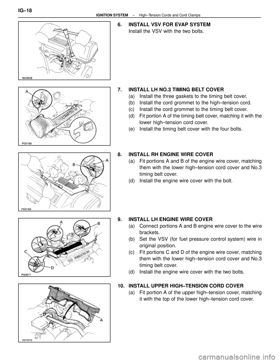
6. INSTALL VSV FOR EVAP SYSTEMInstall the VSV with the two bolts.
7. INSTALL LH NO.3 TIMING BELT COVER (a) Install the three gaskets to the timing belt cover.
(b) Install the cord grommet to the high±tension cord.
(c) Install the cord grommet to the timing belt cover.
(d) Fit portion A of the timing belt cover, matching it with the
lower high±tension cord cover.
(e) Install the timing belt cover with the four bolts.
8. INSTALL RH ENGINE WIRE COVER (a) Fit portions A and B of the engine wire cover, matchingthem with the lower high±tension cord cover and No.3
timing belt cover.
(d) Install the engine wire cover with the bolt.
9. INSTALL LH ENGINE WIRE COVER (a) Connect portions A and B engine wire cover to the wirebrackets.
(b) Set the VSV (for fuel pressure control system) wire in original position.
(c) Fit portions C and D of the engine wire cover, matching them with the lower high±tension cord cover and No.3
timing belt cover.
(d) Install the engine wire cover with the two bolts.
10. INSTALL UPPER HIGH±TENSION CORD COVER (a) Fit portion A of the upper high±tension cover, matchingit with the top of the lower high±tension cord cover.
IG±18
±
IGNITION SYSTEM High±Tension Cords and Cord Clamps
WhereEverybodyKnowsYourName
Page 2584 of 4087
(2) Water by±pass hose from ISC valve
(3) (USA Spec.)Vacuum hose from throttle body
(4) (Exc. USA Spec.)
Three vacuum hoses from throttle body
(c) Remove the two bolts and two nuts, disconnect the throttle body from the air intake chamber.
(d) Disconnect the following hoses, and remove the throttle body:
(1) PCV hose from throttle body
(2) Water by±pass hose from throttle body
(e) Remove the throttle body gasket.
14. DISCONNECT CONNECTORS Disconnect the following connectors:
wCold start injector connector
w ISC valve connector
w (USA Spec.)
EGR Valve connector
w (Exc. USA Spec.)
VSV connector for EGR system
w VSV connector for fuel pressure control system
±
STARTING SYSTEM StarterST±9
WhereEverybodyKnowsYourName
Page 2585 of 4087
15. DISCONNECT HOSESDisconnect the following hoses:(1) Water by±pass hose (from water inlet housing) from ISC valve
(2) Vacuum hose (from PS air control valve) from air in-
take chamber
(3) Vacuum sensing hose (from fuel pressure regula- tor) from vacuum pipe
(4) Two vacuum hoses (from VSV for EVAP system) from vacuum pipe
(5) Vacuum hose (from charcoal canister) from vacu- um pipe.
(6) Water by±pass hose (from EGR valve) from water by±pass pipe
(7) Vacuum hose (from brake booster) from air intake chamber
(8) Vacuum hose (from VSV for heater water valve)
from air intake chamber
(9) PCV hose from LH cylinder head cover
16. REMOVE AIR INTAKE CHAMBER (a) Remove the bolt, stud bolt and accelerator bracket.
ST±10
±
STARTING SYSTEM Starter
WhereEverybodyKnowsYourName
Page 2603 of 4087
12. INSTALL AIR INTAKE CHAMBER(a) Place four new gaskets and the air intake chamber onthe intake manifold.
(b) Temporarily install a new gasket and the EGR pipe to air
intake chamber with the two bolts.
(c) (Exc. USA Spec.) Install the connector bracket to check (ºDIAGNOSISº)
connector.
(d) Install the air intake chamber and following parts with the four bolts and eight nuts:
(1) Check (ºDIAGNOSISº) connector
(2) A/T throttle cable bracket
(3) VSV for fuel pressure control system
(4) VSV for EGR system
Torque: 18 N Vm (185 kgf Vcm, 13 ft Vlbf)
HINT: Use bolts 40 mm (1.57 in.) of length.
ST±28
±
STARTING SYSTEM Starter
WhereEverybodyKnowsYourName
Page 2605 of 4087

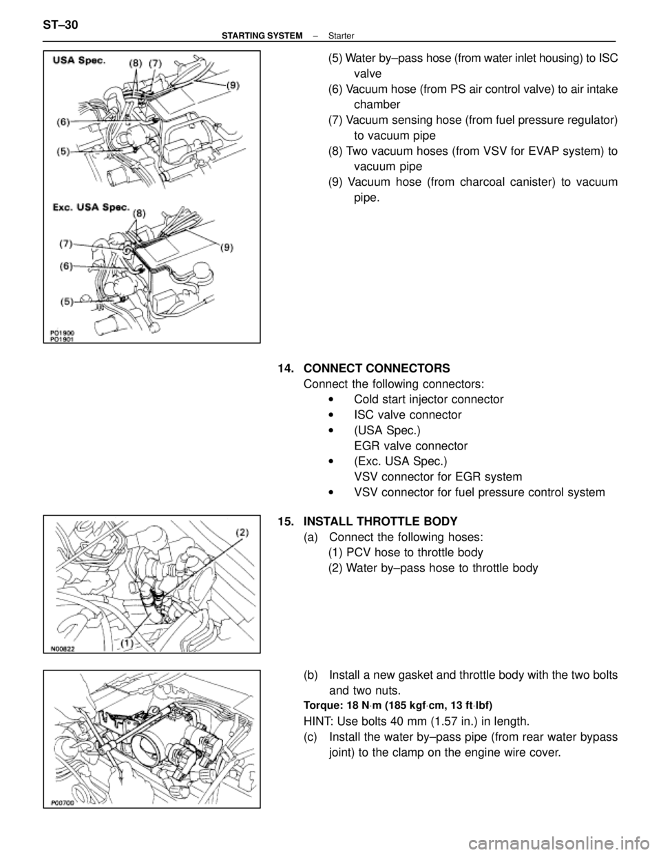
(5) Water by±pass hose (from water inlet housing) to ISC
valve
(6) Vacuum hose (from PS air control valve) to air intake chamber
(7) Vacuum sensing hose (from fuel pressure regulator) to vacuum pipe
(8) Two vacuum hoses (from VSV for EVAP system) to vacuum pipe
(9) Vacuum hose (from charcoal canister) to vacuum pipe.
14. CONNECT CONNECTORS Connect the following connectors:w Cold start injector connector
w ISC valve connector
w (USA Spec.)
EGR valve connector
w (Exc. USA Spec.)
VSV connector for EGR system
w VSV connector for fuel pressure control system
15. INSTALL THROTTLE BODY (a) Connect the following hoses:(1) PCV hose to throttle body
(2) Water by±pass hose to throttle body
(b) Install a new gasket and throttle body with the two bolts and two nuts.
Torque: 18 N Vm (185 kgf Vcm, 13 ft Vlbf)
HINT: Use bolts 40 mm (1.57 in.) in length.
(c) Install the water by±pass pipe (from rear water bypass
joint) to the clamp on the engine wire cover.
ST±30
±
STARTING SYSTEM Starter
WhereEverybodyKnowsYourName
Page 2608 of 4087

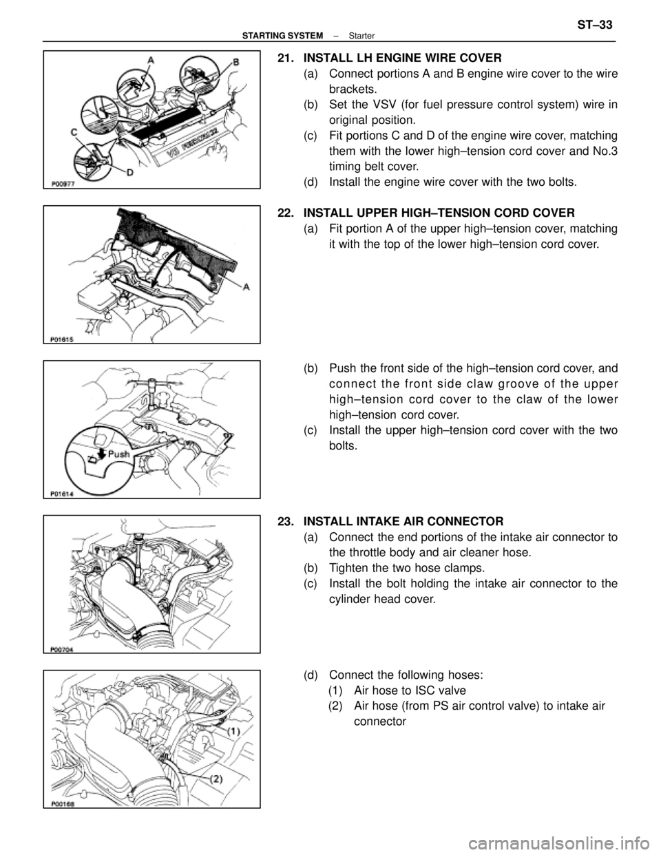
21. INSTALL LH ENGINE WIRE COVER(a) Connect portions A and B engine wire cover to the wirebrackets.
(b) Set the VSV (for fuel pressure control system) wire in
original position.
(c) Fit portions C and D of the engine wire cover, matching them with the lower high±tension cord cover and No.3
timing belt cover.
(d) Install the engine wire cover with the two bolts.
22. INSTALL UPPER HIGH±TENSION CORD COVER (a) Fit portion A of the upper high±tension cover, matchingit with the top of the lower high±tension cord cover.
(b) Push the front side of the high±tension cord cover, and connect the front side claw groove of the upper
high±tension cord cover to the claw of the lower
high±tension cord cover.
(c) Install the upper high±tension cord cover with the two
bolts.
23. INSTALL INTAKE AIR CONNECTOR (a) Connect the end portions of the intake air connector tothe throttle body and air cleaner hose.
(b) Tighten the two hose clamps.
(c) Install the bolt holding the intake air connector to the cylinder head cover.
(d) Connect the following hoses: (1) Air hose to ISC valve
(2) Air hose (from PS air control valve) to intake air connector
±
STARTING SYSTEM StarterST±33
WhereEverybodyKnowsYourName
Page 2611 of 4087

SERVICE SPECIFICATIONS
SERVICE DATA
StarterRated voltage and output power12 V 2.0 kW
No±load characteristicCurrent 120 A or less at 11.5 V
rpm 3,300 rpm or more at 11.5 V
Brush lengthSTD 15.0±15.5 mm0.591±0.610 in.
Limit 9.5 mm0.374 in.
CommutatorOuter diameter STD 35.0 mm1.378 in.
Limit 34.0 mm1.339 in.
Undercut depth STD 0.7±0.9 mm0.028±0.035 in.
Limit 0.2 mm0.008 in.
Circle runout Limit 0.05 mm0.0020 in.
Spring installed load26±32 N
(2.7±3.3 kgf, 6.0±7.3 lbf)
TORQUE SPECIFICATIONS
Part tightenedNVmkgf Vcmft Vlbf
Starter X Cylinder block3940029
Rear water by±pass joint X Cylinder head18185 13
Water by±pass pipe X Cylinder block18185 13
Intake manifold X Cylinder head18185 13
Fuel return pipe X Fuel pressure regulator35360 26
Fuel inlet hose X LH delivery pipe39400 29
for SST 33340 24
Air intake chamber X Intake manifold18185 13
EGR pipe X Air intake chamber18185 13
EGR pipe X RH cylinder head18185 13
Cold start injector tube X RH delivery pipe15150 11
Throttle body X Air intake chamber1818513
ST±36±
STARTING SYSTEM Service Specifications
WhereEverybodyKnowsYourName
Page 2613 of 4087

HOW TO PROCEED WITH TROUBLESHOOTING
The Engine Control System broadly consists of the sensors, ECU and actuator\
s. The ECU receives signals from
various sensors, judges the operating conditions and determines the opti\
mum injection duration, timing, ignition
timing and idle speed.
In general, the Engine Control System is considered to be a very intricate\
system to troubleshoot. But, the fact
is that if you proceed to inspect the circuit one by one following the p\
rocedures directed in this manual, trouble-
shooting of this system is not complex.
This section explains the most ideal method of troubleshooting and tells how\
to carry out the necessary repairs.
[1] CUSTOMER PROBLEM ANALYSISUsing the customer problem analysis check sheet for reference, ask the c\
ustomer in as much details as
possible about the problem.
[2] CHECK AND CLEAR DIAGNOSTIC CODE (PRECHECK) Before confirming the problem symptom, first check the diagnostic code and mak\
e a note of any malfunc-
tion code which is output, then clear the code.
HINT: Output of the malfunction code indicates that there is a malfunction in\
the circuit indicated. However,
it does not indicate whether the malfunction is still occurring or occur\
red in the past and returned to normal.
In order to determine this, the problem symptoms should be confirmed in 4 \
first and the diagnostic code
be rechecked in [6].
Accordingly, if troubleshooting is begun based on the malfunction code only in diag\
nostic code check in
[2] , it could result in a misdiagnosis, leading to troubleshooting of circuits which are normal \
and making
it more difficult to locate the cause of the problem.
[3] SETTING THE TEST MODE DIAGNOSIS, [4] PROBLEM SYMPTOM CONFIRMATION, [5] SYMPTOM SIMULATION
In order to find out the trouble more quickly, set the diagnosis check in test mode and with higher sensing
ability of the ECU, confirm the problem symptoms. If the trouble does not reappear, use the symptom simu-
lation method to make sure the trouble is reproduced.
[6] DIAGNOSTIC CODE CHECK IN TEST MODE Check the diagnostic code in test mode. If the malfunction code is output, pr\
oceed to ºstep [8] Diagnostic
Code Chartº. If the normal code is output, proceed to ºstep [7] Basic Inspectionº.
[7] BASIC INSPECTION Carry out basic inspection such as the spark check and fuel pressure che\
ck, etc.
[8] DIAGNOSTIC CODE CHART If the malfunction code is displayed, proceed to inspect the circuit ind\
icated by the chart for each code.
[9] MATRIX CHART OF PROBLEM SYMPTOMS If the normal code is displayed in the diagnosis in test mode, perform tro\
ubleshooting according to the in-
spection order in the Matrix Chart of Problem Symptoms.
[10] PARTS INSPECTION When the Matrix Chart of Problem Symptoms instructs to check the parts, proc\
eed to parts inspection sec-
tion included in this manual.
[11] CIRCUIT INSPECTION Determine if the malfunction is the sensor, actuator, wire harness, connector or the ECU.
TR±2
±
ENGINE TROUBLESHOOTING How to Proceed with Troubleshooting
WhereEverybodyKnowsYourName