Page 2860 of 4087
3. VISUALLY INSPECT FUEL TANK CAPCheck if the cap and/or gasket are deformed or damaged.
If necessary, repair or replace the cap.
INSPECTION OF CHARCOAL CANISTER
1. REMOVE CHARCOAL CANISTER(a) Disconnect the following hoses:(1) Vacuum hose (from VSV) from charcoal canister
(2) EVAP hose from charcoal canister
(b) Disconnect the grommet on the check valve from the bracket, and remove the charcoal canister.
(c) Remove the check valve from the hose end on the charcoal canister.
2. VISUALLY INSPECT CHARCOAL CANISTER Look for cracks or damage.
3. CHECK FOR CLOGGED FILTER AND STUCK CHECK VA LV E
(a) Using low pressure compressed air, blow into port A and
check that air flows without resistance from the other
ports.
(b) Blow into port B and check that air does not flow from the
other ports.
If a problem is found, replace the charcoal canister.
±
EMISSION CONTROL SYSTEMS Fuel Evaporative Emission Control (EVAP) SystemEC±9
WhereEverybodyKnowsYourName
Page 2890 of 4087

SERVICE SPECIFICATIONS
SERVICE DATA
StarterRated voltage and output power12 V 2.0 kW
No±load characteristicCurrent 120 A or less at 11.5 V
rpm 3,300 rpm or more at 11.5 V
Brush lengthSTD 15.0±15.5 mm0.591±0.610 in.
Limit 9.5 mm0.374 in.
CommutatorOuter diameter STD 35.0 mm1.378 in.
Limit 34.0 mm1.339 in.
Undercut depth STD 0.7±0.9 mm0.028±0.035 in.
Limit 0.2 mm0.008 in.
Circle runout Limit 0.05 mm0.0020 in.
Spring installed load26±32 N
(2.7±3.3 kgf, 6.0±7.3 lbf)
TORQUE SPECIFICATIONS
Part tightenedNVmkgf Vcmft Vlbf
Starter X Cylinder block3940029
Rear water by±pass joint X Cylinder head18185 13
Water by±pass pipe X Cylinder block18185 13
Intake manifold X Cylinder head18185 13
Fuel return pipe X Fuel pressure regulator35360 26
Fuel inlet hose X LH delivery pipe39400 29
for SST 33340 24
Air intake chamber X Intake manifold18185 13
EGR pipe X Air intake chamber18185 13
EGR pipe X RH cylinder head18185 13
Cold start injector tube X RH delivery pipe15150 11
Throttle body X Air intake chamber1818513
ST±36±
STARTING SYSTEM Service Specifications
WhereEverybodyKnowsYourName
Page 2899 of 4087
(2) Water by±pass hose from ISC valve
(3) (USA Spec.)Vacuum hose from throttle body
(4) (Exc. USA Spec.)
Three vacuum hoses from throttle body
(c) Remove the two bolts and two nuts, disconnect the throttle body from the air intake chamber.
(d) Disconnect the following hoses, and remove the throttle body:
(1) PCV hose from throttle body
(2) Water by±pass hose from throttle body
(e) Remove the throttle body gasket.
14. DISCONNECT CONNECTORS Disconnect the following connectors:
wCold start injector connector
w ISC valve connector
w (USA Spec.)
EGR Valve connector
w (Exc. USA Spec.)
VSV connector for EGR system
w VSV connector for fuel pressure control system
±
STARTING SYSTEM StarterST±9
WhereEverybodyKnowsYourName
Page 2900 of 4087
15. DISCONNECT HOSESDisconnect the following hoses:(1) Water by±pass hose (from water inlet housing) from ISC valve
(2) Vacuum hose (from PS air control valve) from air in-
take chamber
(3) Vacuum sensing hose (from fuel pressure regula- tor) from vacuum pipe
(4) Two vacuum hoses (from VSV for EVAP system) from vacuum pipe
(5) Vacuum hose (from charcoal canister) from vacu- um pipe.
(6) Water by±pass hose (from EGR valve) from water by±pass pipe
(7) Vacuum hose (from brake booster) from air intake chamber
(8) Vacuum hose (from VSV for heater water valve)
from air intake chamber
(9) PCV hose from LH cylinder head cover
16. REMOVE AIR INTAKE CHAMBER (a) Remove the bolt, stud bolt and accelerator bracket.
ST±10
±
STARTING SYSTEM Starter
WhereEverybodyKnowsYourName
Page 2918 of 4087
12. INSTALL AIR INTAKE CHAMBER(a) Place four new gaskets and the air intake chamber onthe intake manifold.
(b) Temporarily install a new gasket and the EGR pipe to air
intake chamber with the two bolts.
(c) (Exc. USA Spec.) Install the connector bracket to check (ºDIAGNOSISº)
connector.
(d) Install the air intake chamber and following parts with the four bolts and eight nuts:
(1) Check (ºDIAGNOSISº) connector
(2) A/T throttle cable bracket
(3) VSV for fuel pressure control system
(4) VSV for EGR system
Torque: 18 N Vm (185 kgf Vcm, 13 ft Vlbf)
HINT: Use bolts 40 mm (1.57 in.) of length.
ST±28
±
STARTING SYSTEM Starter
WhereEverybodyKnowsYourName
Page 2920 of 4087

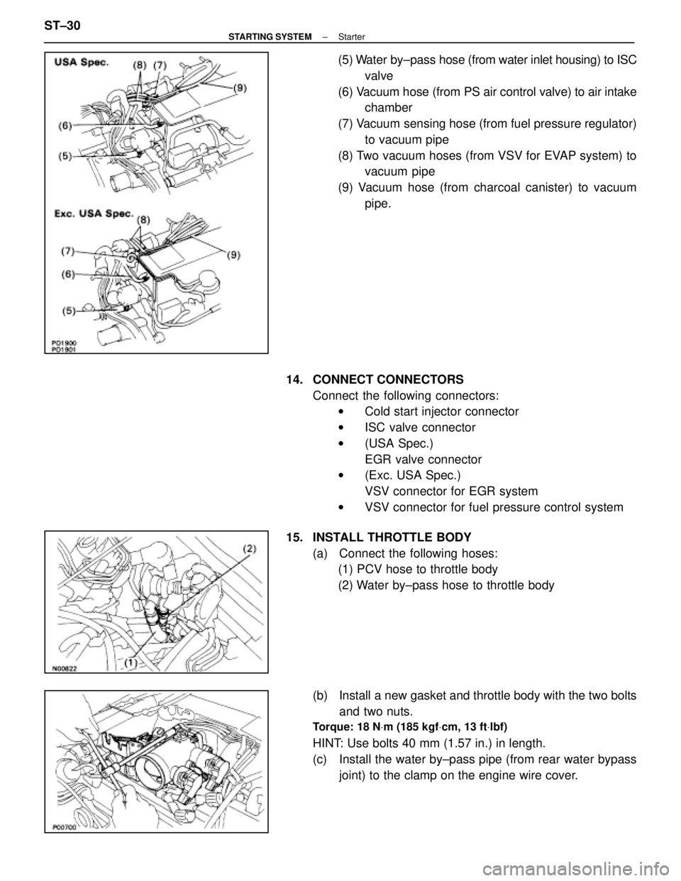
(5) Water by±pass hose (from water inlet housing) to ISC
valve
(6) Vacuum hose (from PS air control valve) to air intake chamber
(7) Vacuum sensing hose (from fuel pressure regulator) to vacuum pipe
(8) Two vacuum hoses (from VSV for EVAP system) to vacuum pipe
(9) Vacuum hose (from charcoal canister) to vacuum pipe.
14. CONNECT CONNECTORS Connect the following connectors:w Cold start injector connector
w ISC valve connector
w (USA Spec.)
EGR valve connector
w (Exc. USA Spec.)
VSV connector for EGR system
w VSV connector for fuel pressure control system
15. INSTALL THROTTLE BODY (a) Connect the following hoses:(1) PCV hose to throttle body
(2) Water by±pass hose to throttle body
(b) Install a new gasket and throttle body with the two bolts and two nuts.
Torque: 18 N Vm (185 kgf Vcm, 13 ft Vlbf)
HINT: Use bolts 40 mm (1.57 in.) in length.
(c) Install the water by±pass pipe (from rear water bypass
joint) to the clamp on the engine wire cover.
ST±30
±
STARTING SYSTEM Starter
WhereEverybodyKnowsYourName
Page 2923 of 4087

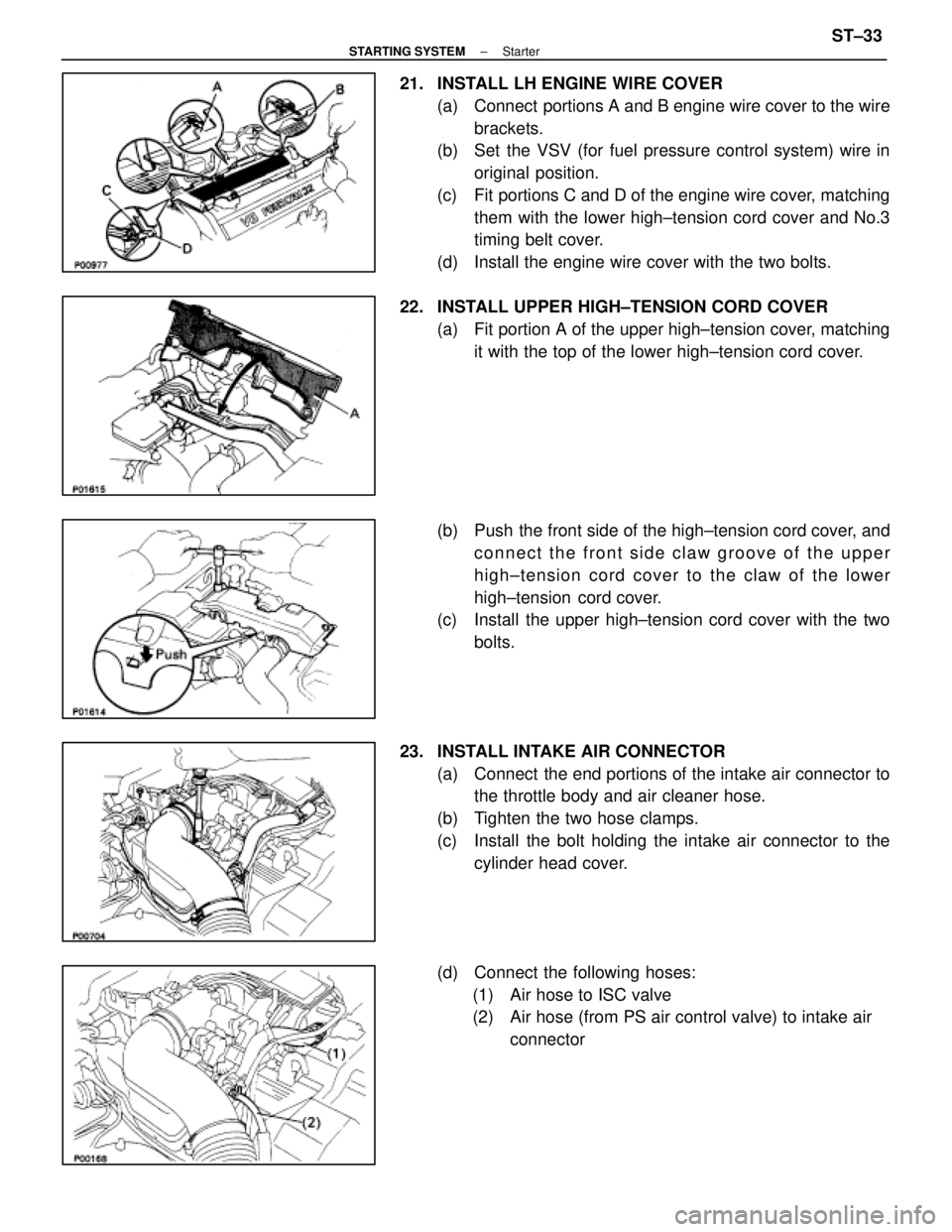
21. INSTALL LH ENGINE WIRE COVER(a) Connect portions A and B engine wire cover to the wirebrackets.
(b) Set the VSV (for fuel pressure control system) wire in
original position.
(c) Fit portions C and D of the engine wire cover, matching them with the lower high±tension cord cover and No.3
timing belt cover.
(d) Install the engine wire cover with the two bolts.
22. INSTALL UPPER HIGH±TENSION CORD COVER (a) Fit portion A of the upper high±tension cover, matchingit with the top of the lower high±tension cord cover.
(b) Push the front side of the high±tension cord cover, and connect the front side claw groove of the upper
high±tension cord cover to the claw of the lower
high±tension cord cover.
(c) Install the upper high±tension cord cover with the two
bolts.
23. INSTALL INTAKE AIR CONNECTOR (a) Connect the end portions of the intake air connector tothe throttle body and air cleaner hose.
(b) Tighten the two hose clamps.
(c) Install the bolt holding the intake air connector to the cylinder head cover.
(d) Connect the following hoses: (1) Air hose to ISC valve
(2) Air hose (from PS air control valve) to intake air connector
±
STARTING SYSTEM StarterST±33
WhereEverybodyKnowsYourName
Page 3368 of 4087
Fuel Pressure Control VSV Circuit
CIRCUIT DESCRIPTION
The ECU turns on a VSV (Vacuum Switching Valve)
to draw the air into the diaphragm chamber of the
pressure regulator if it detects that the temperature of
the coolant is too high during engine starting.
The air drawn into the chamber increases the fuel
pressure to prevent fuel vapor lock at high engine
temperature in order to help the engine start when it
is warm.
Fuel pressure control ends approx. 100 secs. after
the engine is started.
DIAGNOSTIC CHARTDIAGNOSTIC CHART
Check operation for fuel pressure control
VSV.Replace fuel pressure control VSV.
Repair or replace harness or
connector.
Proceed to next circuit inspection
shown on matrix chart (See page
TR±35).
Check for open and short in harness and
connector between main relay and ECU.
Check voltage of VSV power source.
Check and replace ECU.
WIRING DIAGRAM
TR±142±
ENGINE TROUBLESHOOTING Circuit Inspection
WhereEverybodyKnowsYourName