Page 2357 of 4087
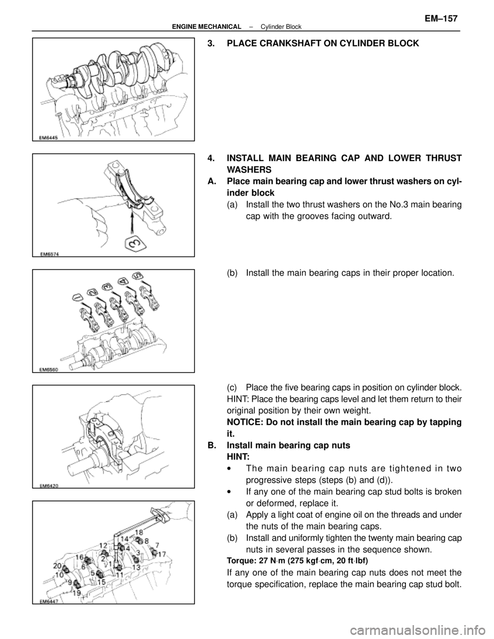
3. PLACE CRANKSHAFT ON CYLINDER BLOCK
4. INSTALL MAIN BEARING CAP AND LOWER THRUSTWASHERS
A. Place main bearing cap and lower thrust washers on cyl-
inder block
(a) Install the two thrust washers on the No.3 main bearing cap with the grooves facing outward.
(b) Install the main bearing caps in their proper location.
(c) Place the five bearing caps in position on cylinder block.
HINT: Place the bearing caps level and let them return to their
original position by their own weight.
NOTICE: Do not install the main bearing cap by tapping
it.
B. Install main bearing cap nuts HINT:
wThe main bearing cap nuts are tightened in two
progressive steps (steps (b) and (d)).
w If any one of the main bearing cap stud bolts is broken
or deformed, replace it.
(a) Apply a light coat of engine oil on the threads and under
the nuts of the main bearing caps.
(b) Install and uniformly tighten the twenty main bearing cap
nuts in several passes in the sequence shown.
Torque: 27 N Vm (275 kgf Vcm, 20 ft Vlbf)
If any one of the main bearing cap nuts does not meet the
torque specification, replace the main bearing cap stud bolt.
±
ENGINE MECHANICAL Cylinder BlockEM±157
WhereEverybodyKnowsYourName
Page 2359 of 4087
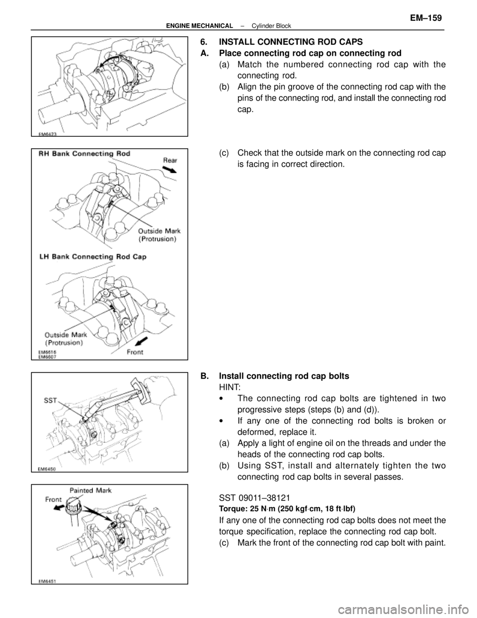
6. INSTALL CONNECTING ROD CAPS
A. Place connecting rod cap on connecting rod(a) Match the numbered c onnecting rod cap with the
connecting rod.
(b) Align the pin groove of the connecting rod cap with the pins of the connecting rod, and install the connecting rod
cap.
(c) Check that the outside mark on the connecting rod cap is facing in correct direction.
B. Install connecting rod cap bolts HINT:
wThe connecting rod cap bolts are tightened in two
progressive steps (steps (b) and (d)).
w If any one of the connecting rod bolts is broken or
deformed, replace it.
(a) Apply a light of engine oil on the threads and under the
heads of the connecting rod cap bolts.
(b) Usin g SS T, in sta ll an d alte rn a te ly tig h te n th e two connecting rod cap bolts in several passes.
SST 09011±38121
Torque: 25 N Vm (250 kgf Vcm, 18 ft Vlbf)
If any one of the connecting rod cap bolts does not meet the
torque specification, replace the connecting rod cap bolt.
(c) Mark the front of the connecting rod cap bolt with paint.
±
ENGINE MECHANICAL Cylinder BlockEM±159
WhereEverybodyKnowsYourName
Page 2360 of 4087
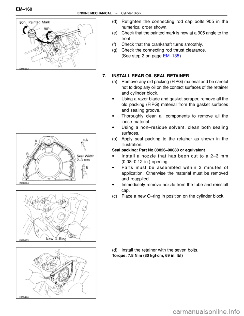
(d) Retighten the connecting rod cap bolts 905 in thenumerical order shown.
(e) Check that the painted mark is now at a 905 angle to the
front.
(f) Check that the crankshaft turns smoothly.
(g) Check the connecting rod thrust clearance. (See step 2 on page EM±135)
7. INSTALL REAR OIL SEAL RETAINER (a) Remove any old packing (FIPG) material and be carefulnot to drop any oil on the contact surfaces of the retainer
and cylinder block.
w Using a razor blade and gasket scraper, remove all the
old packing (FIPG) material from the gasket surfaces
and sealing groove.
w Thoroughly clean all components to remove all the
loose material.
w Using a non±residue solvent, clean both sealing
surfaces.
(b) Apply seal packing to the retainer as shown in the illustration.
Seal packing: Part No.08826±00080 or equivalent
wInstall a nozzle that has been cut to a 2±3 mm
(0.08±0.12 in.) opening.
w Parts must be assembled within 3 minutes of
application. Otherwise the material must be removed
and reapplied.
w Immediately remove nozzle from the tube and reinstall
cap.
(c) Place a new O±ring in position on the cylinder block.
(d) Install the retainer with the seven bolts.
Torque: 7.8 N Vm (80 kgf Vcm, 69 in. Vlbf)
EM±160±
ENGINE MECHANICAL Cylinder Block
WhereEverybodyKnowsYourName
Page 2361 of 4087
POST ASSEMBLY
(See Components on page EM±131)
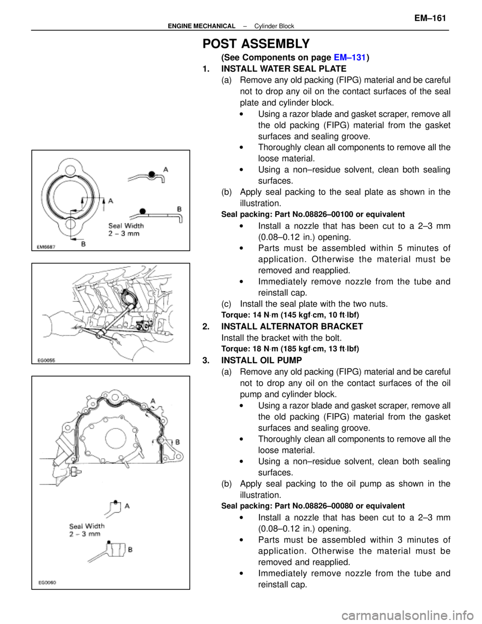
1. INSTALL WATER SEAL PLATE (a) Remove any old packing (FIPG) material and be careful
not to drop any oil on the contact surfaces of the seal
plate and cylinder block.
w Using a razor blade and gasket scraper, remove all
the old packing (FIPG) material from the gasket
surfaces and sealing groove.
w Thoroughly clean all components to remove all the
loose material.
w Using a non±residue solvent, clean both sealing
surfaces.
(b) Apply seal packing to the seal plate as shown in the
illustration.
Seal packing: Part No.08826±00100 or equivalent
w Install a nozzle that has been cut to a 2±3 mm
(0.08±0.12 in.) opening.
w Parts must be assembled within 5 minutes of
application. Otherwise the material must be
removed and reapplied.
w Immediately remove nozzle from the tube and
reinstall cap.
(c) Install the seal plate with the two nuts.
Torque: 14 N Vm (145 kgf Vcm, 10 ft Vlbf)
2. INSTALL ALTERNATOR BRACKET
Install the bracket with the bolt.
Torque: 18 N Vm (185 kgf Vcm, 13 ft Vlbf)
3. INSTALL OIL PUMP
(a) Remove any old packing (FIPG) material and be carefulnot to drop any oil on the contact surfaces of the oil
pump and cylinder block.
w Using a razor blade and gasket scraper, remove all
the old packing (FIPG) material from the gasket
surfaces and sealing groove.
w Thoroughly clean all components to remove all the
loose material.
w Using a non±residue solvent, clean both sealing
surfaces.
(b) Apply seal packing to the oil pump as shown in the
illustration.
Seal packing: Part No.08826±00080 or equivalent
w Install a nozzle that has been cut to a 2±3 mm
(0.08±0.12 in.) opening.
w Parts must be assembled within 3 minutes of
application. Otherwise the material must be
removed and reapplied.
w Immediately remove nozzle from the tube and
reinstall cap.
±
ENGINE MECHANICAL Cylinder BlockEM±161
WhereEverybodyKnowsYourName
Page 2362 of 4087
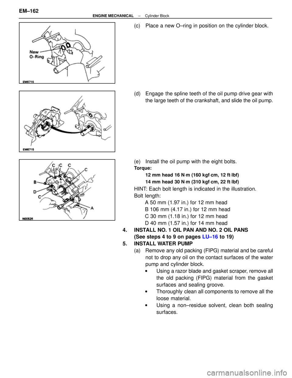
(c) Place a new O±ring in position on the cylinder block.
(d) Engage the spline teeth of the oil pump drive gear withthe large teeth of the crankshaft, and slide the oil pump.
(e) Install the oil pump with the eight bolts.
Torque: 12 mm head 16 N Vm (160 kgf Vcm, 12 ft Vlbf)
14 mm head 30 N Vm (310 kgf Vcm, 22 ft Vlbf)
HINT: Each bolt length is indicated in the illustration.
Bolt length:
A 50 mm (1.97 in.) for 12 mm head
B 106 mm (4.17 in.) for 12 mm head
C 30 mm (1.18 in.) for 12 mm head
D 40 mm (1.57 in.) for 14 mm head
4. INSTALL NO. 1 OIL PAN AND NO. 2 OIL PANS (See steps 4 to 9 on pages LU±16 to 19)
5. INSTALL WATER PUMP (a) Remove any old packing (FIPG) material and be carefulnot to drop any oil on the contact surfaces of the water
pump and cylinder block.
w Using a razor blade and gasket scraper, remove all
the old packing (FIPG) material from the gasket
surfaces and sealing groove.
w Thoroughly clean all components to remove all the
loose material.
w Using a non±residue solvent, clean both sealing
surfaces.
EM±162
±
ENGINE MECHANICAL Cylinder Block
WhereEverybodyKnowsYourName
Page 2363 of 4087
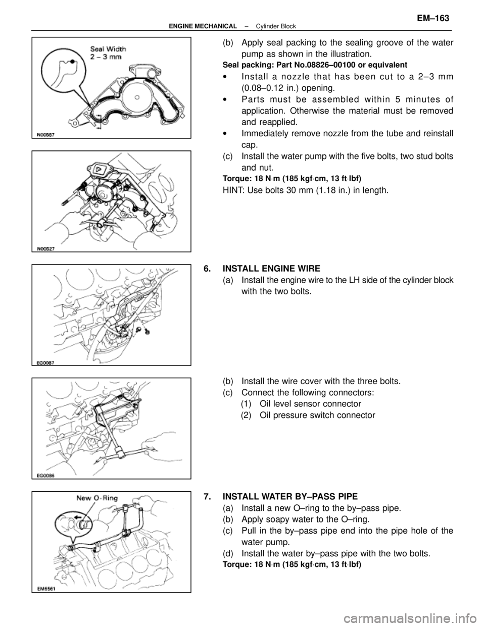
(b) Apply seal packing to the sealing groove of the waterpump as shown in the illustration.
Seal packing: Part No.08826±00100 or equivalent
wInstall a nozzle that has been cut to a 2±3 mm
(0.08±0.12 in.) opening.
w Parts must be assembled within 5 minutes of
application. Otherwise the material must be removed
and reapplied.
w Immediately remove nozzle from the tube and reinstall
cap.
(c) Install the water pump with the five bolts, two stud bolts and nut.
Torque: 18 N Vm (185 kgf Vcm, 13 ft Vlbf)
HINT: Use bolts 30 mm (1.18 in.) in length.
6. INSTALL ENGINE WIRE (a) Install the engine wire to the LH side of the cylinder block
with the two bolts.
(b) Install the wire cover with the three bolts.
(c) Connect the following connectors: (1) Oil level sensor connector
(2) Oil pressure switch connector
7. INSTALL WATER BY±PASS PIPE (a) Install a new O±ring to the by±pass pipe.
(b) Apply soapy water to the O±ring.
(c) Pull in the by±pass pipe end into the pipe hole of thewater pump.
(d) Install the water by±pass pipe with the two bolts.
Torque: 18 N Vm (185 kgf Vcm, 13 ft Vlbf)
±
ENGINE MECHANICAL Cylinder BlockEM±163
WhereEverybodyKnowsYourName
Page 2365 of 4087
12. INSTALL CYLINDER HEADS(See pages EM±92 to 115)
13. INSTALL TIMING PULLEYS AND BELT (See pages EM±48 to 57)
14. REMOVE ENGINE STAND FROM ENGINE
15. INSTALL DRIVE PLATE (a) Apply adhesive to two or three threads of the mountingbolt end.
Adhesive: Part No.08833±00070, THREE BOND 1324 or equiva-
lent
(b) Install the front spacer, drive plate and rear spacer on the crankshaft.
(c) Install and uniformly tighten the eight mounting bolts in
several passes in the sequence shown.
Torque: 98 N Vm (1,000 kgf Vcm, 72 ft Vlbf)
ASSEMBLY OF ENGINE AND
TRANSMISSION
(See Components on page EM±129)
1. ASSEMBLE ENGINE AND TRANSMISSION (See AT section)
2. INSTALL OIL COOLER PIPE (a) Temporarily install the two mounting bolts.
(b) Connect the two oil cooler pipes to the unions on thetransmission. Tighten the union nuts.
Torque: 34 N Vm (350 kgf Vcm, 25 ft Vlbf)
±
ENGINE MECHANICAL Cylinder BlockEM±165
WhereEverybodyKnowsYourName
Page 2366 of 4087
3. INSTALL DIPSTICK GUIDE FOR TRANSMISSION(a) Install a new O±ring to the dipstick guide.
(b) Apply soapy water to the O±ring.
(c) Connect the dipstick guide end to the tube of the oil pan,
and install the dipstick guide with the bolt.
(d) Install the dipstick.
4. CONNECT ENGINE WIRE TO TRANSMISSION (a) Connect the following connectors:(1) O/D direct clutch speed sensor connector
(2) No.1 speed sensor connector
(3) No.2 speed sensor connector
(4) Neutral start switch connector
(b) Install the five wire clamps to the brackets on the transmission.
EM±166±
ENGINE MECHANICAL Cylinder Block
WhereEverybodyKnowsYourName