Page 2394 of 4087
Preparation
SST (SPECIAL SERVICE TOOLS)
IllustrationPart No.Part NameNote
09268±41045Injection Measuring
Tool Set
(90268±41070)No. 4 Union
Injector
(09268±41080)No. 6 Union
Cold start Injector
(09268±52010)Injection Measuring
Attachment
Injector
09268±45012EFI Fuel Pressure
Gauge
09612±24014
Steering Gear
Housing Overhaul
Tool Set
(09617±24011)Steering Rack Wrench
Fuel pressure pulsation damper
09631±22020
Power Steering
Hose Nut 14 X 17 mm
Wrench SetFuel line flare nut
09816±30010Oil Pressure
Switch SocketKnock sensor
09842±30055Wire ªGº
EFI Inspection
Cold start Injector
09842±30070Wire ªFº
EFI Inspection
Injector
09843±18020Diagnosis Check
Wire
0990±01000
Engine Control
Computer
Check Harness ªAº
FI±10 ± PreparationEFI SYSTEM
WhereEverybodyKnowsYourName
Page 2396 of 4087
 terminal of the battery.
HINT: Any diagnostic code retained by the computer will be
erased when the battery t")
PRECAUTIONS
1. Before working on the fuel system, disconnect the cablefrom negative (±) terminal of the battery.
HINT: Any diagnostic code retained by the computer will be
erased when the battery terminal is removed. Therefore, if
necessary, read the diagnosis before removing the battery
terminal.
CAUTION: Work must be started after approx. 20 se-
conds or longer from the time the ignition switch is
turned to the ºLOCKº position and negative (±) terminal
cable is disconnected from the battery.
2. Do not smoke or work on open flame when working on the fuel system.
3. Keep gasoline away from rubber or leather parts.
INSPECTION PRECAUTIONS
MAINTENANCE PRECAUTIONS
1. CHECK CORRECT ENGINE TUNE±UP (See page EM±8)
2. PRECAUTIONS WHEN CONNECTING GAUGE (a) Use the battery as the power source for the timing light,tachometer, etc.
(b) Connect the test probe of a tachometer to the terminal IG of the check connector.
3. IN EVENT OF ENGINE MISFIRE, FOLLOWING PRECAUTIONS SHOULD BE TAKEN
(a) Check proper connection of battery terminals, etc.
(b) Handle high±tension cords carefully.
(c) After repair work, check that the ignition coil terminalsand all other ignition system lines are reconnected
securely.
(d) When cleaning the engine compartment, be especially careful to protect the electrical system from water.
4. PRECAUTIONS WHEN HANDLING OXYGEN SENSOR (a) Do not allow oxygen sensor to drop or hit against anobject.
(b) Do not allow the sensor to come into contact with water.
FI±12
± Precautions, Inspection PrecautionsEFI SYSTEM
WhereEverybodyKnowsYourName
Page 2402 of 4087
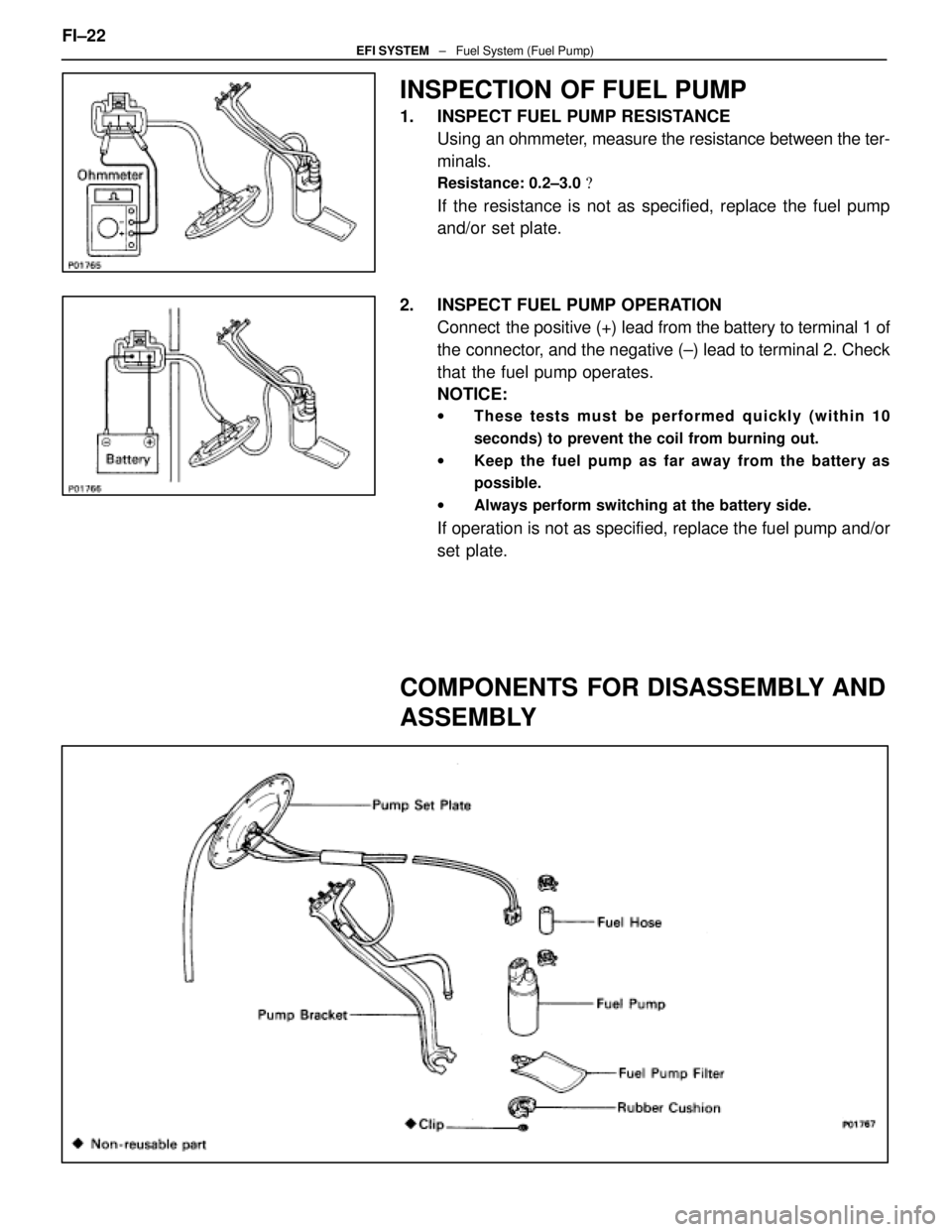
INSPECTION OF FUEL PUMP
1. INSPECT FUEL PUMP RESISTANCEUsing an ohmmeter, measure the resistance between the ter-
minals.
Resistance: 0.2±3.0 �
If the resistance is not as specified, replace the fuel pump
and/or set plate.
2. INSPECT FUEL PUMP OPERATION Connect the positive (+) lead from the battery to terminal 1 of
the connector, and the negative (±) lead to terminal 2. Check
that the fuel pump operates.
NOTICE:
w These tests must be performed quickly (within 10
seconds) to prevent the coil from burning out.
w Keep the fuel pump as far away from the battery as
possible.
w Always perform switching at the battery side.
If operation is not as specified, replace the fuel pump and/or
set plate.
COMPONENTS FOR DISASSEMBLY AND
ASSEMBLY
FI±22EFI SYSTEM ± Fuel System (Fuel Pump)
WhereEverybodyKnowsYourName
Page 2409 of 4087
11. REMOVE LH NO.3 TIMING BELT COVER(a) Remove the four mounting bolts.
(b) Disconnect the cord grommet from the timing belt cover,
and remove the timing belt cover.
(c) Remove the cord grommet from the high±tension cord.
12. REMOVE LOWER HIGH±TENSION CORD COVER (a) Disconnect the high±tension cord from the RH ignitioncoil.
(b) D i s c onnect the high±tension cords from the
high±tension cord cover.
(c) Remove the bolt and cord cover.
13. REMOVE THROTTLE BODY (a) Disconnect the following connectors:(1) Throttle position sensor connector
(2) (w/ TRAC) Sub±throttle position sensor connector
(3) (w/ TRAC) Sub±throttle actuator connector
(b) Disconnect the following hoses: (1) Heater water hose from heater water valve FI±29
EFI SYSTEM
± Fuel System (Cold Start Injector)
WhereEverybodyKnowsYourName
Page 2419 of 4087
(4) Heater water hose to heater water valve
(e) Connect the following connectors: (1) Throttle position sensor connector
(2) (w/ TRAC)
Sub±throttle position sensor connector
(3) (w/ TRAC) Sub±throttle actuator connector
5. INSTALL LOWER HIGH±TENSION CORD COVER (a) Connect the end portions of the high±tension cord to the
cord clamps
(b) Install the high±tension cord cover with the bolt.
(c) Install the clamps on the high±tension cords to the
high±tension cord cover.
(d) Connect the high±tension cord to the RH ignition coil.
7. INSTALL RH NO.3 TIMING BELT COVER (a) Install the three gaskets to the timing belt cover.
(b) Fit portion A of the timing belt cover, matching it with the
lower high±tension cord cover.
(c) Install the timing belt cover with the three bolts. FI±39
EFI SYSTEM
± Fuel System (Cold Start Injector)
WhereEverybodyKnowsYourName
Page 2468 of 4087

2. REMOVE RH IGNITION COIL (a) Disconnect the ignition coi")
INSPECTION OF COLD START
INJECTOR TIME SWITCH
1. REMOVE LOWER HIGH±TENSION CORD COVER(See steps 1, 2 and 5 to 12 on pages FI±27 to 29)
2. REMOVE RH IGNITION COIL (a) Disconnect the ignition coil connector.
(b) Remove the two bolts, and disconnect the ignition coil.
(c) Disconnect the cam position sensor connector from the
ignition coil bracket, and remove the ignition coil.
3. REMOVE COLD START INJECTOR TIME SWITCH (a) Disconnect the injector time switch connector.
(b) Remove the injector time switch and gasket.
4. INSPECT COLD START INJECTOR TIME SWITCH Using an ohmmeter, measure the resistance between each
terminal.
Resistance:
STA±STJ 25±45 � below 15 °C (59 °F)
65±85 � above 30 °C (86 °F)
STA±Ground 25±85 �
If the resistance is not as specified, replace the switch.
5. REINSTALL COLD START INJECTOR TIME SWITCH (a) Install a new gasket to the injector time switch.
(b) Install the injector time switch.
Torque: 34 N Vm (350 kgf Vcm, 25 ft Vlbf)
(c) Connect the injector time switch connector.
6. REINSTALL RH IGNITION COIL (a) Install the ignition coil with the two bolts.
FI±88
EFI SYSTEM
± Electronic Control System (Cold Start Injector Time Switch)
WhereEverybodyKnowsYourName
Page 2469 of 4087
(b) Install the cam position sensor connector to the ignitioncoil bracket.
(c) Connect the ignition coil connector.
7. REINSTALL LOWER HIGH±TENSION CORD COVER (See steps 1 to 13 and 16 to 18 on pages FI±39 to 41)FI±89
EFI SYSTEM
± Electronic Control System (Cold Start Injector Time Switch)
WhereEverybodyKnowsYourName
Page 2479 of 4087

2. REMOVE RH IGNITION COIL (a) Disconnect the ignition coil conne")
INSPECTION OF WATER TEMPERATURE
SENSOR
1. REMOVE LOWER HIGH±TENSION CORD COVER(See steps 1, 2 and 5 to 12 on pages FI±27 to 29)
2. REMOVE RH IGNITION COIL (a) Disconnect the ignition coil connector.
(b) Remove the two bolts, and disconnect the ignition coil.
(c) Disconnect the cam position sensor connector from the
ignition coil bracket, and remove the ignition coil.
3. DISCONNECT HOSES Disconnect the following hoses:(1) Upper radiator hose from front water by±pass joint
(2) Lower radiator hose from water inlet
(3) Radiator reservoir hose from front water inlet hous-
ing
4. REMOVE WATER INLET AND INLET HOUSING (a) Disconnect the water by±pass hose from the water inlethousing.
(b) Remove the two bolts holding the water inlet housing to the water pump.
(c) Pull out the water inlet and inlet housing assembly.
(d) Remove the O±ring from the water inlet housing.
5. REMOVE WATER TEMPERATURE SENSOR (a) Disconnect the water temperature sensor connector.
(b) Remove the water temperature sensor and gasket. FI±99
EFI SYSTEM
± Electronic Control System (Water Temperature Sensor)
WhereEverybodyKnowsYourName

IllustrationPart No.Part NameNote
09268±41045Injection Measuring
Tool Set
(90268±41070)No. 4 Union
Injector
(09268±41080)No. 6 Union
Cold start Injector
(09")
 Remove the four mounting bolts.
(b) Disconnect the cord grommet from the timing belt cover,
and remove the timing belt cover.
(c) Remove the cord grommet")
 Heater water hose to heater water valve
(e) Connect the following connectors: (1) Throttle position sensor connector
(2) (w/ TRAC)
Sub±throttle position sensor connector
(3) (w/ TRAC) Sub±thro")
 Install the cam position sensor connector to the ignitioncoil bracket.
(c) Connect the ignition coil connector.
7. REINSTALL LOWER HIGH±TENSION CORD COVER (See steps 1 to 13 and 16 to 18 on p")