Page 2348 of 4087

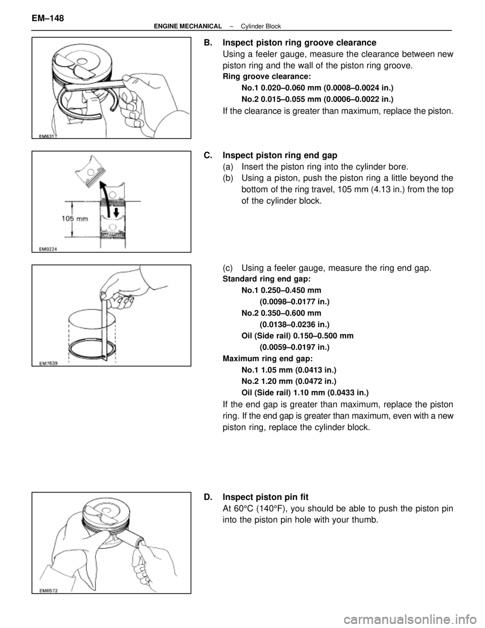
B. Inspect piston ring groove clearanceUsing a feeler gauge, measure the clearance between new
piston ring and the wall of the piston ring groove.
Ring groove clearance:
No.1 0.020±0.060 mm (0.0008±0.0024 in.)
No.2 0.015±0.055 mm (0.0006±0.0022 in.)
If the clearance is greater than maximum, replace the piston.
C. Inspect piston ring end gap (a) Insert the piston ring into the cylinder bore.
(b) Using a piston, push the piston ring a little beyond thebottom of the ring travel, 105 mm (4.13 in.) from the top
of the cylinder block.
(c) Using a feeler gauge, measure the ring end gap.
Standard ring end gap: No.1 0.250±0.450 mm(0.0098±0.0177 in.)
No.2 0.350±0.600 mm (0.0138±0.0236 in.)
Oil (Side rail) 0.150±0.500 mm
(0.0059±0.0197 in.)
Maximum ring end gap: No.1 1.05 mm (0.0413 in.)
No.2 1.20 mm (0.0472 in.)
Oil (Side rail) 1.10 mm (0.0433 in.)
If the end gap is greater than maximum, replace the piston
ring. If the end gap is greater than maximum, even with a new
piston ring, replace the cylinder block.
D. Inspect piston pin fit At 60 5C (140 5F), you should be able to push the piston pin
into the piston pin hole with your thumb.
EM±148
±
ENGINE MECHANICAL Cylinder Block
WhereEverybodyKnowsYourName
Page 2349 of 4087

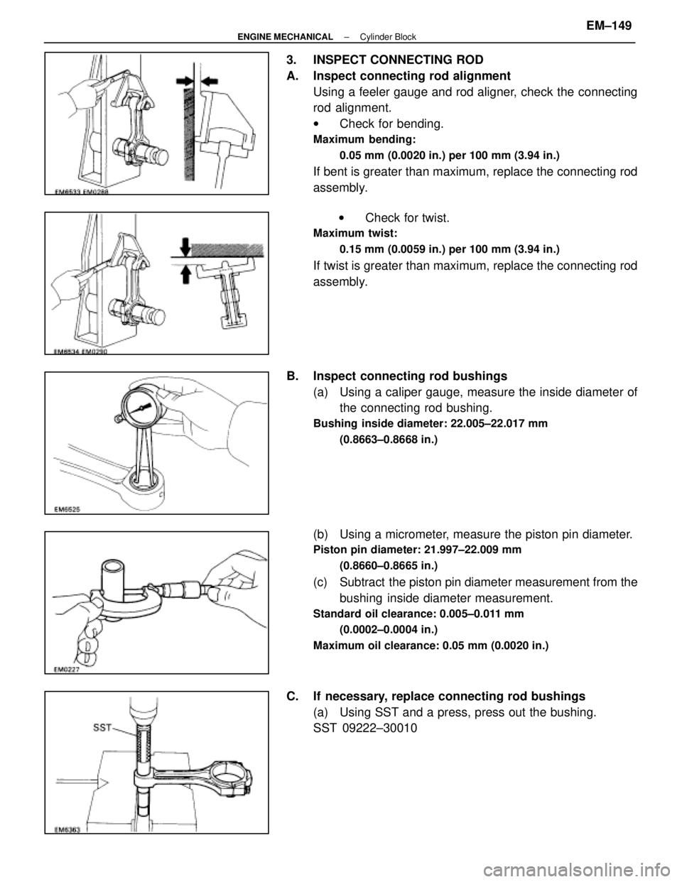
3. INSPECT CONNECTING ROD
A. Inspect connecting rod alignmentUsing a feeler gauge and rod aligner, check the connecting
rod alignment.
wCheck for bending.
Maximum bending:
0.05 mm (0.0020 in.) per 100 mm (3.94 in.)
If bent is greater than maximum, replace the connecting rod
assembly.
w Check for twist.
Maximum twist:
0.15 mm (0.0059 in.) per 100 mm (3.94 in.)
If twist is greater than maximum, replace the connecting rod
assembly.
B. Inspect connecting rod bushings (a) Using a caliper gauge, measure the inside diameter ofthe connecting rod bushing.
Bushing inside diameter: 22.005±22.017 mm
(0.8663±0.8668 in.)
(b) Using a micrometer, measure the piston pin diameter.
Piston pin diameter: 21.997±22.009 mm(0.8660±0.8665 in.)
(c) Subtract the piston pin diameter measurement from thebushing inside diameter measurement.
Standard oil clearance: 0.005±0.011 mm
(0.0002±0.0004 in.)
Maximum oil clearance: 0.05 mm (0.0020 in.)
C. If necessary, replace connecting rod bushings (a) Using SST and a press, press out the bushing.
SST 09222±30010
±
ENGINE MECHANICAL Cylinder BlockEM±149
WhereEverybodyKnowsYourName
Page 2350 of 4087
(b) Align the oil holes of the connecting rod and a newbushing.
(c) Using SST and a press, press in the bushing.
SST 09222±30010
(d) Using a pin hole grinder, hole the bushing to obtain the standard specified clearance (see step B above)
between the bushing and piston pin.
(e) Check the piston pin fit at normal room temperature.
Coat the piston pin with engine oil, and push it into the con-
necting rod with your thumb.
D. Inspect connecting rod bolts Using a vernier caliper, measure the tension portion diameter
of the bolt.
Standard diameter: 7.200±7.300 mm
(0.2835±0.2874 in.)
Minimum diameter: 7.00 mm (0.2756 in.)
If the outside diameter is less than minimum, replace the bolt.
EM±150
±
ENGINE MECHANICAL Cylinder Block
WhereEverybodyKnowsYourName
Page 2351 of 4087
INSPECTION OF CRANKSHAFT
1. INSPECT CRANKSHAFT FOR RUNOUT(a) Place the crankshaft on V±blocks.
(b) Using a dial indicator, measure the circle runout at thecenter journal.
Maximum circle runout: 0.08 mm (0.0031 in.)
If the circle runout is greater than maximum, replace the
crankshaft.
2. INSPECT MAIN JOURNALS AND CRANK PINS (a) Using a micr ometer, measure the diameter of each main
journal and crank pin.
Main journal diameter: 66.988±67.000 mm
(2.6373±2.6378 in.)
Crank pin diameter: 51.982±52.000 mm (2.0465±2.0472 in.)
If the diameter is not as specified, check the oil clearance
(See page EM±136 or 139).
(b) Check each main journal and crank pin for taper and out±of±round as shown.
Maximum taper and out±of±round: 0.02 mm
(0.0008 in.)
If the taper or out±of±round is greater than maximum, re-
place the crankshaft.
±
ENGINE MECHANICAL Cylinder BlockEM±151
WhereEverybodyKnowsYourName
Page 2352 of 4087
REPLACEMENT OF CRANKSHAFT OIL
SEALS
HINT: There are two methods (A and B) to replace the oil seal
which are as follows:
1. REPLACE CRANKSHAFT FRONT OIL SEAL
A. If oil pump is removed from cylinder block: (a) Using a screwdriver, pry out the oil seal.
(b) Using SST and a hammer, tap in a new oil seal until its
surface is flush with the oil pump body edge.
SST 09316±60010 (09316±00010)
(c) Apply MP grease to the oil seal lip.
B. If oil pump is installed to the cylinder block: (a) Using a knife, cut off the oil seal lip.
(b) Using a screwdriver, pry out the oil seal.
NOTICE: Be careful not to damage the crankshaft. Tape
the screwdriver tip.
(c) Apply MP grease to a new oil seal lip.
(d) Using SST and a hammer, tap in the oil seal until itssurface is flush with the oil pump body edge.
SST 09316±60010 (09316±00010)
EM±152
±
ENGINE MECHANICAL Cylinder Block
WhereEverybodyKnowsYourName
Page 2353 of 4087
2. REPLACE CRANKSHAFT REAR OIL SEAL
A. If rear oil seal retainer is removed from cylinder block:(a) Using a screwdriver and hammer, tap out the oil seal.
(b) Using SST and a hammer, tap in a new oil seal until itssurface is flush with the rear oil seal retainer edge.
SST 09223±56010
(c) Apply MP grease to the oil seal lip.
B. If rear oil seal retainer is installed to cylinder block: (a) Using a knife, cut off the oil seal lip.
(b) Using a screwdriver, pry out the oil seal.
NOTICE: Be careful not to damage the crankshaft.
Tape the screwdriver tip.
(c) Apply MP grease to a new oil seal lip.
(d) Using SST and a hammer, tap in the oil seal until itssurface is flush with the rear oil seal retainer edge.
SST 09223±56010
±
ENGINE MECHANICAL Cylinder BlockEM±153
WhereEverybodyKnowsYourName
Page 2355 of 4087
2. INSTALL PISTON RINGS(a) Install the oil ring expander and two side rails by hand.
(b) U s i n g a p i s t o n r i n g e x pander, install the two
compression rings with the code mark facing upward.
Code mark: No.1 1R or T
No.2 2R or 2T
(c) Position the piston rings so that the ring ends are asshown.
NOTICE: Do not align the piston ring ends.
3. INSTALL BEARINGS (a) Align the bearing claw with the groove of the connectingrod or connecting cap.
(b) I n s t a l l t h e b e a r i n g s i n t h e c onnecting rod and
connecting rod cap.
±
ENGINE MECHANICAL Cylinder BlockEM±155
WhereEverybodyKnowsYourName
Page 2356 of 4087

ASSEMBLY OF CYLINDER BLOCK
(See Components on page EM±131)
HINT:
w Thoroughly clean all parts to be assembled.
w Before installing the parts, apply new engine oil to all
sliding and rotating surfaces.
w Replace all gaskets, O±rings and oil seals with new
parts.
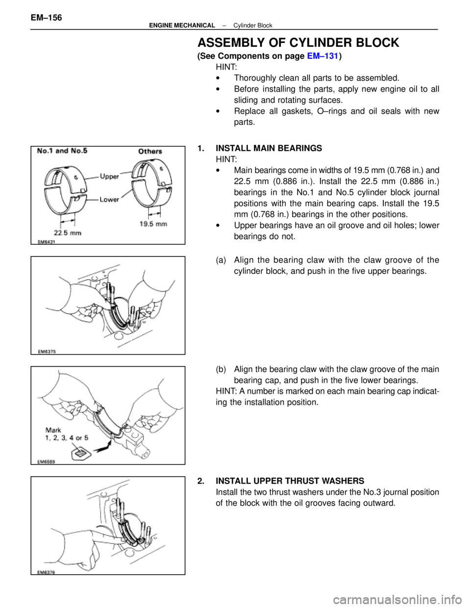
1. INSTALL MAIN BEARINGS HINT:
wMain bearings come in widths of 19.5 mm (0.768 in.) and
22.5 mm (0.886 in.). Install the 22.5 mm (0.886 in.)
bearings in the No.1 and No.5 cylinder block journal
positions with the main bearing caps. Install the 19.5
mm (0.768 in.) bearings in the other positions.
w Upper bearings have an oil groove and oil holes; lower
bearings do not.
(a) Align the bearing claw with the claw groove of the cylinder block, and push in the five upper bearings.
(b) Align the bearing claw with the claw groove of the main bearing cap, and push in the five lower bearings.
HINT: A number is marked on each main bearing cap indicat-
ing the installation position.
2. INSTALL UPPER THRUST WASHERS Install the two thrust washers under the No.3 journal position
of the block with the oil grooves facing outward.
EM±156
±
ENGINE MECHANICAL Cylinder Block
WhereEverybodyKnowsYourName