Page 2254 of 4087

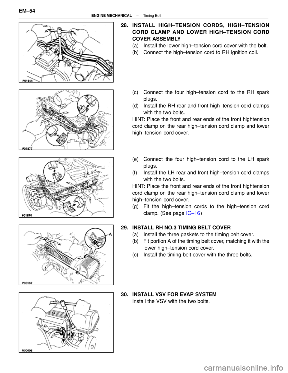
28. INSTALL HIGH±TENSION CORDS, HIGH±TENSIONCORD CLAMP AND LOWER HIGH±TENSION CORD
COVER ASSEMBLY
(a) Install the lower high±tension cord cover with the bolt.
(b) Connect the high±tension cord to RH ignition coil.
(c) Connect the four high±tension cord to the RH sparkplugs.
(d) Install the RH rear and front high±tension cord clamps
with the two bolts.
HINT: Place the front and rear ends of the front hightension
cord clamp on the rear high±tension cord clamp and lower
high±tension cord cover.
(e) Connect the four high±tension cord to the LH spark plugs.
(f) Install the LH rear and front high±tension cord clamps
with the two bolts.
HINT: Place the front and rear ends of the front hightension
cord clamp on the rear high±tension cord clamp and lower
high±tension cord cover.
(g) Fit the high±tension cords to the high±tension cord clamp. (See page IG±16)
29. INSTALL RH NO.3 TIMING BELT COVER (a) Install the three gaskets to the timing belt cover.
(b) Fit portion A of the timing belt cover, matching it with the
lower high±tension cord cover.
(c) Install the timing belt cover with the three bolts.
30. INSTALL VSV FOR EVAP SYSTEM Install the VSV with the two bolts.
EM±54
±
ENGINE MECHANICAL Timing Belt
WhereEverybodyKnowsYourName
Page 2256 of 4087
35. INSTALL LH IGNITION COIL(a) Install the ignition coil with the two bolts.
(b) Connect the following connectors and cord:(1) Ignition coil connector
(2) Noise filter connector
(3) High±tension cord
36. INSTALL INTAKE AIR CONNECTOR (a) Connect the end portions of the intake air connector tothe throttle body and air cleaner hose.
(b) Tighten the two hose clamps.
(c) Install the bolt holding the intake air connector to the cylinder head cover.
(d) Connect the following hoses: (1) Air hose to ISC valve
(2) Air hose (from PS air control valve) to intake air connector
EM±56
±
ENGINE MECHANICAL Timing Belt
WhereEverybodyKnowsYourName
Page 2260 of 4087

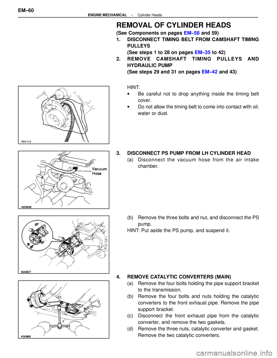
REMOVAL OF CYLINDER HEADS
(See Components on pages EM±58 and 59)
1. DISCONNECT TIMING BELT FROM CAMSHAFT TIMING PULLEYS
(See steps 1 to 28 on pages EM±35 to 42)
2. REMOVE CAMSHAFT TIMING PULLEYS AND HYDRAULIC PUMP
(See steps 29 and 31 on pages EM±42 and 43)
HINT:
w Be careful not to drop anything inside the timing belt
cover.
w Do not allow the timing belt to come into contact with oil,
water or dust.
3. DISCONNECT PS PUMP FROM LH CYLINDER HEAD (a) Disc onnect the vacuum hose from the air intake
chamber.
(b) Remove the three bolts and nut, and disconnect the PS pump.
HINT: Put aside the PS pump, and suspend it.
4. REMOVE CATALYTIC CONVERTERS (MAIN) (a) Remove the four bolts holding the pipe support bracketto the transmission.
(b) Remove the four bolts and nuts holding the catalytic converters to the front exhaust pipe. Remove the pipe
support bracket.
(c) Disconnect the front exhaust pipe from the catalytic
converter, and remove the two gaskets.
(d) Remove the three nuts, catalytic converter and gasket. Remove the two catalytic converters.
EM±60
±
ENGINE MECHANICAL Cylinder Heads
WhereEverybodyKnowsYourName
Page 2261 of 4087
5. REMOVE THROTTLE BODY COVER(a) Remove the mounting cap nut.
(b) Loosen the two bolts, and remove the throttle bodycover.
6. DISCONNECT CONTROL CABLES FROM THROTTLE BODY
Disconnect the following cables:(1) Accelerator cable
(2) A/T throttle control cable
(3) (w/ Cruise Control System) Cruise control actuator cable
7. REMOVE RH IGNITION COIL Remove the two bolts and ignition coil.
8. REMOVE WATER INLET AND INLET HOUSING (a) Disconnect the water by±pass hose from the ISC valve.
(b) Remove the two bolts holding the water inlet housing to the water pump.
(c) Pull out the water inlet and inlet housing assembly.
(d) Remove the O±ring from the water inlet housing.
±
ENGINE MECHANICAL Cylinder HeadsEM±61
WhereEverybodyKnowsYourName
Page 2269 of 4087
(c) Remove the four nuts, water by±pass joint and twogaskets.
31. REMOVE REAR WATER BY±PASS JOINT (a) Remove the bolt holding the water by±pass pipe to theengine hanger.
(b) Remove the four nuts, water by±pass joint and two gaskets.
32. REMOVE OIL DIPSTICK AND GUIDE FOR ENGINE (a) Remove the mounting bolt.
(b) Pull out the dipstick guide together with the dipstick.
(c) Remove the O±ring from the dipstick guide.
33. REMOVE OIL DIPSTICK AND GUIDE FOR A/T
34. REMOVE EGR PIPE (a) Remove the two nuts holding the EGR pipe to the RHexhaust pipe.
(b) Remove the EGR pipe and gasket.
35. DISCONNECT GROUND STRAP FROM RH CYLINDER HEAD
36. DISCONNECT ENGINE WIRE FROM RH CYLINDER HEAD
Remove the two bolts, and disconnect the engine wire.
±
ENGINE MECHANICAL Cylinder HeadsEM±69
WhereEverybodyKnowsYourName
Page 2271 of 4087
(c) Set the timing mark (one dot mark) of the camshaftdriven gear at approx. 105 angle by turning the hexagon
wrench head portion of the exhaust camshaft with a
wrench.
(d) Alternately loosen and remove the two bearing cap bolts
holding the intake camshaft side of the oil feed pipe to
the cylinder head.
(e) Uniformly loosen and remove the eight bearing cap bolts in several passes in the sequence shown.
(f) Re mo ve th e oil fe e d pip e , fo u r be a rin g ca p s an d
exhaust camshaft.
B. Remove intake camshaft from RH cylinder head (a) Remove the rear bearing cap.
(b) Set the timing mark ( one dot mark) of the camshaft drive
gear at approx. 455 angle by turning the hexagon
wrench head portion of the intake camshaft with a
wrench.
(c) Uniformly loosen and remove the eight bearing cap bolts in several passes in the sequence shown.
(d) Remove the four bearing caps, oil seal and intake
camshaft.
±
ENGINE MECHANICAL Cylinder HeadsEM±71
WhereEverybodyKnowsYourName
Page 2272 of 4087

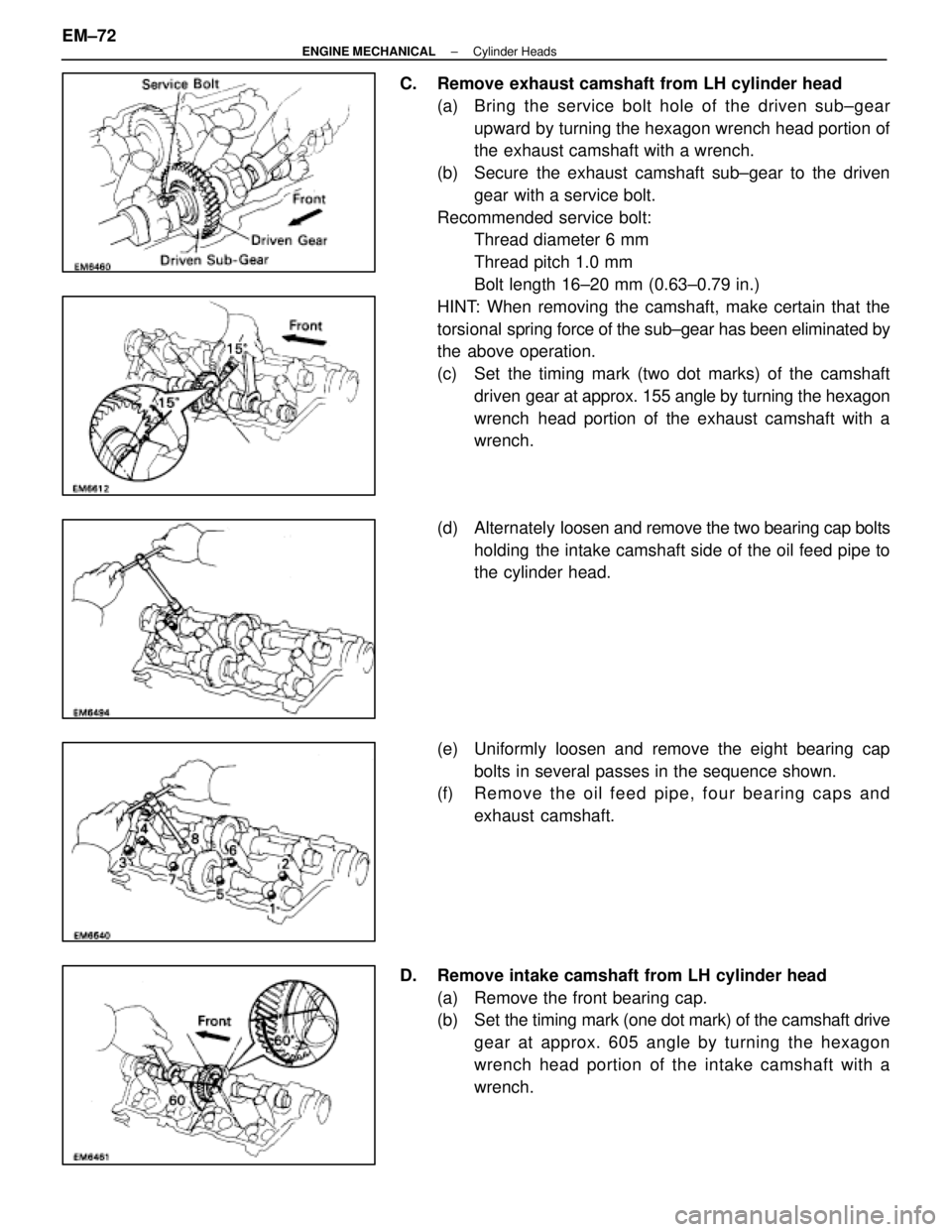
C. Remove exhaust camshaft from LH cylinder head(a) Bring the service bolt hole of the driven s ub±gear
upward by turning the hexagon wrench head portion of
the exhaust camshaft with a wrench.
(b) Secure the exhaust camshaft sub±gear to the driven gear with a service bolt.
Recommended service bolt: Thread diameter 6 mm
Thread pitch 1.0 mm
Bolt length 16±20 mm (0.63±0.79 in.)
HINT: When removing the camshaft, make certain that the
torsional spring force of the sub±gear has been eliminated by
the above operation.
(c) Set the timing mark (two dot marks) of the camshaft
driven gear at approx. 155 angle by turning the hexagon
wrench head portion of the exhaust camshaft with a
wrench.
(d) Alternately loosen and remove the two bearing cap bolts
holding the intake camshaft side of the oil feed pipe to
the cylinder head.
(e) Uniformly loosen and remove the eight bearing cap bolts in several passes in the sequence shown.
(f) Re mo ve th e oil fe e d pip e , fo u r be a rin g ca p s an d
exhaust camshaft.
D. Remove intake camshaft from LH cylinder head (a) Remove the front bearing cap.
(b) Set the timing mark ( one dot mark) of the camshaft drive
gear at approx. 605 angle by turning the hexagon
wrench head portion of the intake camshaft with a
wrench.
EM±72
±
ENGINE MECHANICAL Cylinder Heads
WhereEverybodyKnowsYourName
Page 2273 of 4087
(c) Uniformly loosen and remove the eight bearing capbolts in several passes in the sequence shown.
(d) Remove the four bearing caps, oil seal and intake camshaft.
HINT: Arrange the bearing caps in correct order.
42. DISASSEMBLE EXHAUST CAMSHAFTS (a) M ount the hexagon wrench head portion of the
camshaft in a vise.
NOTICE: Be careful not to damage the camshaft.
(b) Insert a service bolt (A) into the service hole of the camshaft sub±gear.
(c) Using a screwdriver, turn the sub±gear clockwise, and
remove the service bolt (B).
NOTICE: Be careful not to damage the camshaft.
(d) Using snap ring pliers, remove the snap ring.
±
ENGINE MECHANICAL Cylinder HeadsEM±73
WhereEverybodyKnowsYourName