Page 568 of 4087

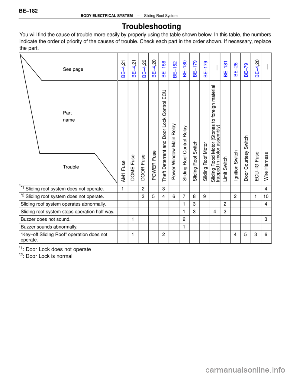
Troubleshooting
You will find the cause of trouble more easily by properly using the tabl\
e shown below. In this table, the numbers
indicate the order of priority of the causes of trouble. Check each part in the \
order shown. If necessary, replace
the part.
See page
BE±4,21BE±4,21BE±4,20BE±4,20BE±156BE±152BE±180BE±179BE±179 ±±BE±181BE±26BE±79BE±4,20 ±±
Part
name
Trouble
AM1 FuseDOME FuseDOOR FusePOWER FuseTheft Deterrent and Door Lock Control ECUPower Window Main RelaySliding Roof Control RelaySliding Roof SwitchSliding Roof MotorSliding Rood Motor (Stones to foreign material
trapped in motor assembly)Limit SwitchIgnition SwitchDoor Courtesy SwitchECU±IG FuseWire Harness
*1 Sliding roof system does not operate.1234
*2 Sliding roof system does not operate.35467892110
Sliding roof system operates abnormally.1324
Sliding roof system stops operation half way.1342
Buzzer does not sound.123
Buzzer sounds abnormally.1
ªKey±off Sliding Roofº operation does not
operate.124536
*1: Door Lock does not operate
*2: Door Lock is normal
BE±182
±
BODY ELECTRICAL SYSTEM Sliding Roof System
WhereEverybodyKnowsYourName
Page 603 of 4087
ANTENNA CORD
ANTENNA CORD REMOVAL AND
INSTALLATION
1. REMOVE ANTENNA CORD
(a) Remove the following parts:wInstrument panel assembly
w Right front pillar garnish
w Roof headlining
w Roof side inner garnish
w Right center pillar garnish
w Right rear pillar garnish
w Package tray trim
w Room partition trim
w Luggage compartment RH cover
w Luggage compartment trim front cover
HINT: (See BO±section.)
(b) Remove antenna cord from motor antenna and glass printed antenna.
(c) Disconnect the connectors shown in the figure.
(d) Remove the clips and antenna cord assembly.
2. INSTALL ANTENNA CORD For installation follow the removal procedure in reverse.
±
BODY ELECTRICAL SYSTEM AUDIO SYSTEMBE±217
WhereEverybodyKnowsYourName
Page 814 of 4087

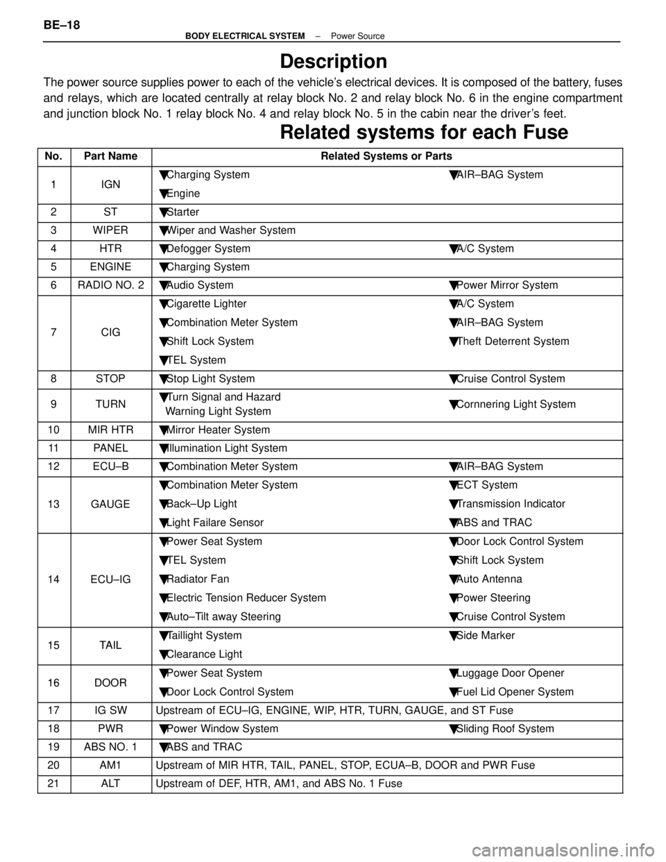
Description
The power source supplies power to each of the vehicle's electrical devices. It is composed of the battery, fuses
and relays, which are located centrally at relay block No. 2 and relay block No. 6 i\
n the engine compartment
and junction block No. 1 relay block No. 4 and relay block No. 5 in the \
cabin near the driver's feet.
Related systems for each Fuse
No.Part NameRelated Systems or Parts
1IGN � Charging System � AIR±BAG System1IGN � Engine
2ST � Starter
3WIPER � Wiper and Washer System
4HTR � Defogger System � A/C System
5ENGINE � Charging System
6RADIO NO. 2 � Audio System � Power Mirror System
� Cigarette Lighter � A/C System
7CIG � Combination Meter System � AIR±BAG System7CIG � Shift Lock System � Theft Deterrent System
� TEL System
8STOP � Stop Light System � Cruise Control System
9TURN � Turn Signal and Hazard
Warning Light System � Cornnering Light System
10MIR HTR � Mirror Heater System
11PANEL � Illumination Light System
12ECU±B � Combination Meter System � AIR±BAG System
� Combination Meter System � ECT System
13GAUGE � Back±Up Light � Transmission Indicator
� Light Failare Sensor � ABS and TRAC
� Power Seat System � Door Lock Control System
� TEL System � Shift Lock System
14ECU±IG � Radiator Fan � Auto Antenna
� Electric Tension Reducer System � Power Steering
� Auto±Tilt away Steering � Cruise Control System
15TAIL � Taillight System � Side Marker15TAIL � Clearance Light
16DOOR � Power Seat System � Luggage Door Opener16DOOR � Door Lock Control System � Fuel Lid Opener System
17IG SWUpstream of ECU±IG, ENGINE, WIP, HTR, TURN, GAUGE, and ST Fuse
18PWR � Power Window System � Sliding Roof System
19ABS NO. 1 � ABS and TRAC
20AM1Upstream of MIR HTR, TAIL, PANEL, STOP, ECUA±B, DOOR and PWR Fuse
21ALTUpstream of DEF, HTR, AM1, and ABS No. 1 Fuse
BE±18±
BODY ELECTRICAL SYSTEM Power Source
WhereEverybodyKnowsYourName
Page 815 of 4087
No.Part NameRelated Systems or Parts
22MAIN � Upstream of ALT±S and EFI Fuse
23AM2 � Charging System � Engine23AM2 � AIR±BAG System
24ABS NO. 2 � ABS and TRAC
25INJ � Charging System � Engine25INJ � AIR±BAG System
26DEF � Defogger System
� Power Seat System � Sliding Roof System
� A/C System � Liquid Crystal Inner Mirror System
27DOME � Combination Meter System � Interior Light System27DOME � ABS and TRAC � Wireless Door Lock Control System
� Cruise Control System � Auto±Tilt away Steering
� Theft Deterrent System
28EFI � Engine
29HAZ HORN � Turn Signal and Hazard Warning Light System29HAZ±HORN � Horn System
30RADIO NO. 1 � Audio System
31TEL � TEL System
32ALT±S � Charging System
33TRAC � ABS and TRAC
34HEAD (RH±LWR) � Headlight System
35HEAD (LH±LWR) � Headlight System
36HEAD (RH±UPR) � Headlight System
37HEAD (LH±UPR) � Headlight System
38HTR � Blow Motor
±
BODY ELECTRICAL SYSTEM Power SourceBE±19
WhereEverybodyKnowsYourName
Page 1157 of 4087
Front Door Trim Upper Panel (ABS/PVC)
Battery Insulator (PE) Roof Side Inner Garnish (ABS/PVC)
Front Pillar Garnish (ABS/PVC)
Speed Control Actuator Cover (PP)
Radiator Reserver Tank (PP)
Radiator Cover Plate (PP) Cool Air Intake
Duct (PP)
Spare Wheel Cover (PP)
Washer Jar (PP)
Junction Block Cover (PP)
Front Fender Liner (PE)
Front Fender Splash Shield (PE)
Engine Under Cover (PE) Engine Under Cover (PE)
Engine Under Cover (PP/PE)
HINT:
wResin material differs with model.
/ Made up of 2 or more kinds of materials.
PLASTIC BODY PARTSPP-5
WhereEverybodyKnowsYourName
Page 1182 of 4087
mm in.30
40
60 1.18
1.57
2.36
FRONT BODY PILLAR (CUT): w/o Moon Roof
REMOVAL (With the cowl top side panel removed.)
Cut and Join
Location
40 mm
60 mm
30 mm 30 mm
Cut and Join Location
(Cut Location for Supply Parts)
[Cut and Join Location]
1. Cut and join the parts at the locations shown above.
HINT: Shift each cut and join location of the outer
pillar, front body pillar upper reinforcement, innerpillar and the roof drip channel.
BODY PANEL REPLACEMENTRE-25
WhereEverybodyKnowsYourName
Page 1184 of 4087
INSTALLATION
Cut and Join
LocationButt Weld
Roof Drip Channel
Butt Weld
1. After installing the new parts, apply foamed material.
HINT: For the foamed material application areas,
refer to page AP-4.
BODY PANEL REPLACEMENTRE-27
WhereEverybodyKnowsYourName
Page 1185 of 4087
mm in.30
100 1.18
3.34
FRONT BODY PILLAR (CUT): w/ Moon Roof
REMOVAL (With the cowl top side panel removed.)
Cut and Join
Location
[Cut and Join Location]
100 mm
30 mm 30 mm
[Cut and Join Location]
Cut and Join Location
(Cut Location for Supply Parts)
1. Cut and join the part at the locations shown
above.
HINT: Shift each cut and join location of the outer
pillar, front body pillar upper reinforcement androof drip channel.
BODY PANEL REPLACEMENTRE-28
WhereEverybodyKnowsYourName