1991 LEXUS SC300 roof
[x] Cancel search: roofPage 1986 of 4087
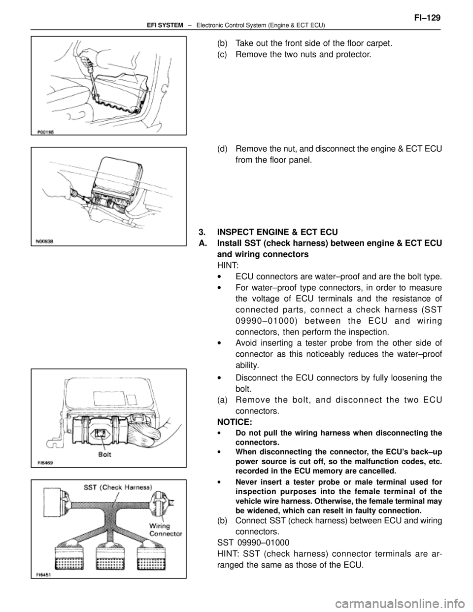
(b) Take out the front side of the floor carpet.
(c) Remove the two nuts and protector.
(d) Remove the nut, and disconnect the engine & ECT ECU
from the floor panel.
3. INSPECT ENGINE & ECT ECU
A. Install SST (check harness) between engine & ECT ECU and wiring connectors
HINT:
wECU connectors are water±proof and are the bolt type.
w For water±proof type connectors, in order to measure
the voltage of ECU terminals and the resistance of
connected parts, connect a check harness (SST
09990±01000) between the ECU and wiring
connectors, then perform the inspection.
w Avoid inserting a tester probe from the other side of
connector as this noticeably reduces the water±proof
ability.
w Disconnect the ECU connectors by fully loosening the
bolt.
(a) Remove the bolt, and disconnect the two ECU
connectors.
NOTICE:
w Do not pull the wiring harness when disconnecting the
connectors.
w When disconnecting the connector, the ECU's back±up
power source is cut off, so the malfunction codes, etc.
recorded in the ECU memory are cancelled.
w Never insert a tester probe or male terminal used for
inspection purposes into the female terminal of the
vehicle wire harness. Otherwise, the female terminal may
be widened, which can reselt in faulty connection.
(b) Connect SST (check harness) between ECU and wiring
connectors.
SST 09990±01000
HINT: SST (check harness) connector terminals are ar-
ranged the same as those of the ECU. FI±129
EFI SYSTEM
± Electronic Control System (Engine & ECT ECU)
WhereEverybodyKnowsYourName
Page 2025 of 4087
8. Care is required when pulling out and inserting wiring
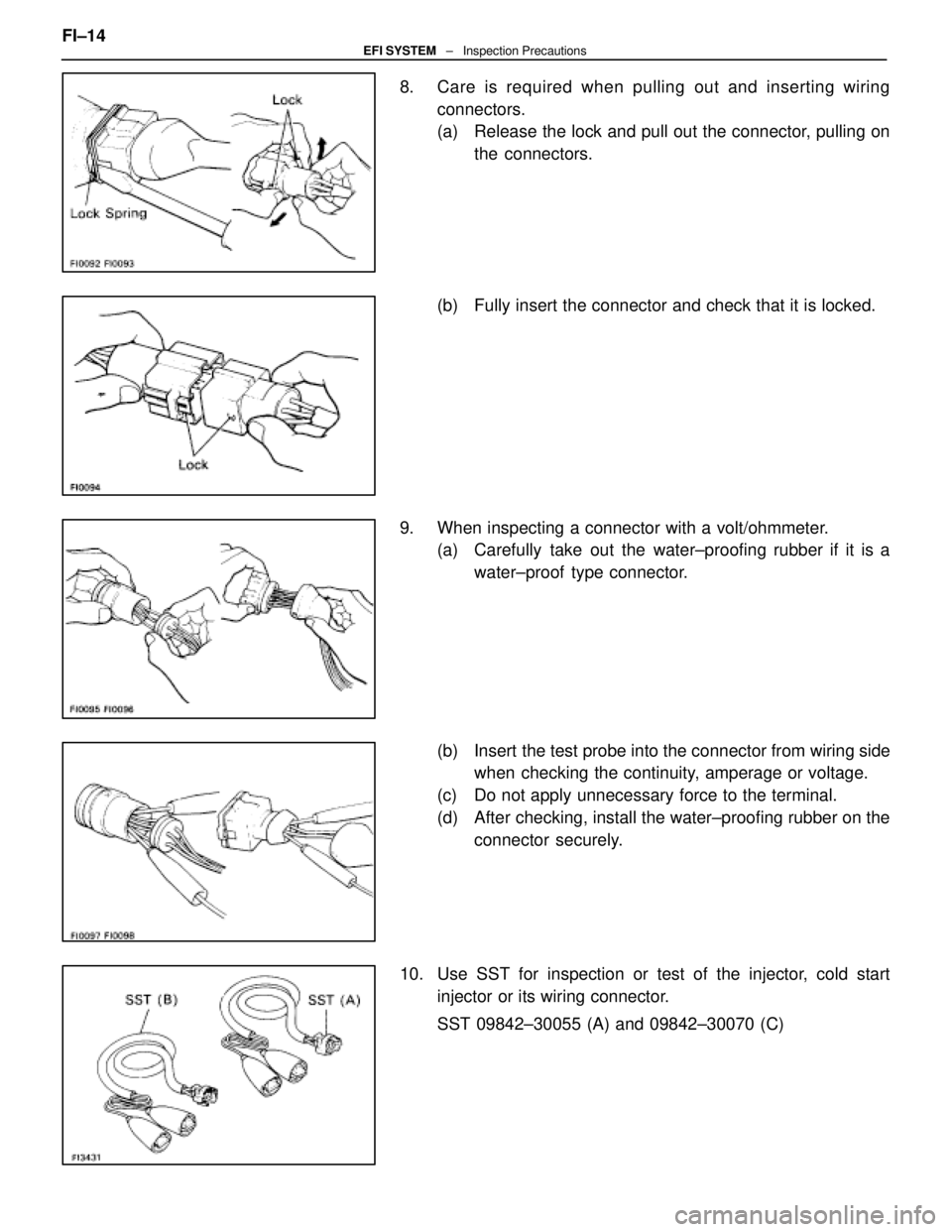
connectors.
(a) Release the lock and pull out the connector, pulling on the connectors.
(b) Fully insert the connector and check that it is locked.
9. When inspecting a connector with a volt/ohmmeter. (a) Carefully take out the water±proofing rubber if it is a
water±proof type connector.
(b) Insert the test probe into the connector from wiring side when checking the continuity, amperage or voltage.
(c) Do not apply unnecessary force to the terminal.
(d) After checking, install the water±proofing rubber on the connector securely.
10. Use SST for inspection or test of the injector, cold start injector or its wiring connector.
SST 09842±30055 (A) and 09842±30070 (C)
FI±14
EFI SYSTEM
± Inspection Precautions
WhereEverybodyKnowsYourName
Page 2509 of 4087
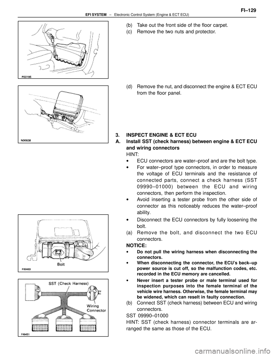
(b) Take out the front side of the floor carpet.
(c) Remove the two nuts and protector.
(d) Remove the nut, and disconnect the engine & ECT ECU
from the floor panel.
3. INSPECT ENGINE & ECT ECU
A. Install SST (check harness) between engine & ECT ECU and wiring connectors
HINT:
wECU connectors are water±proof and are the bolt type.
w For water±proof type connectors, in order to measure
the voltage of ECU terminals and the resistance of
connected parts, connect a check harness (SST
09990±01000) between the ECU and wiring
connectors, then perform the inspection.
w Avoid inserting a tester probe from the other side of
connector as this noticeably reduces the water±proof
ability.
w Disconnect the ECU connectors by fully loosening the
bolt.
(a) Remove the bolt, and disconnect the two ECU
connectors.
NOTICE:
w Do not pull the wiring harness when disconnecting the
connectors.
w When disconnecting the connector, the ECU's back±up
power source is cut off, so the malfunction codes, etc.
recorded in the ECU memory are cancelled.
w Never insert a tester probe or male terminal used for
inspection purposes into the female terminal of the
vehicle wire harness. Otherwise, the female terminal may
be widened, which can reselt in faulty connection.
(b) Connect SST (check harness) between ECU and wiring
connectors.
SST 09990±01000
HINT: SST (check harness) connector terminals are ar-
ranged the same as those of the ECU. FI±129
EFI SYSTEM
± Electronic Control System (Engine & ECT ECU)
WhereEverybodyKnowsYourName
Page 2641 of 4087
TERMINALS OF ECU
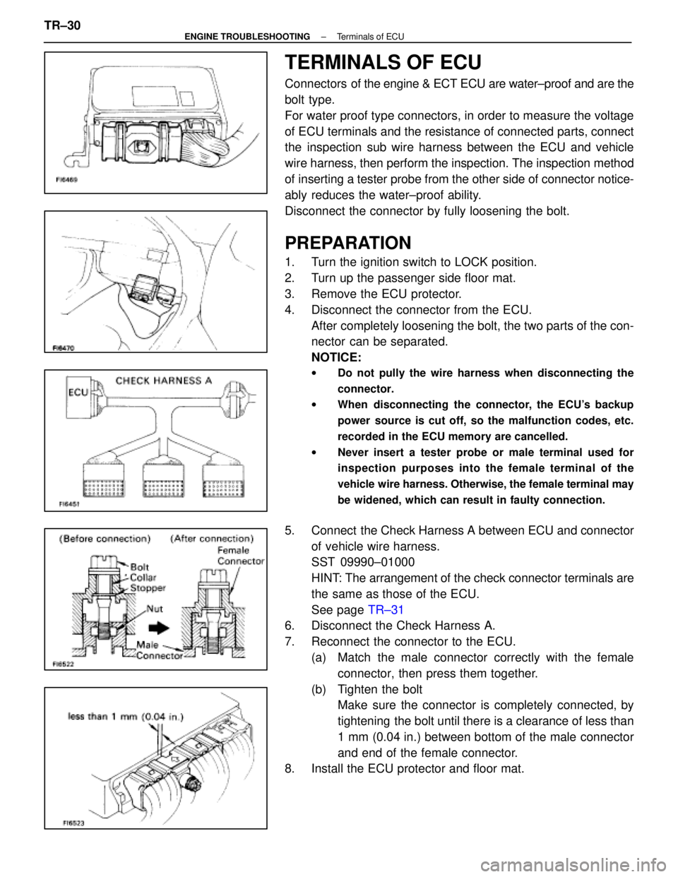
Connectors of the engine & ECT ECU are water±proof and are the
bolt type.
For water proof type connectors, in order to measure the voltage
of ECU terminals and the resistance of connected parts, connect
the inspection sub wire harness between the ECU and vehicle
wire harness, then perform the inspection. The inspection method
of inserting a tester probe from the other side of connector notice-
ably reduces the water±proof ability.
Disconnect the connector by fully loosening the bolt.
PREPARATION
1. Turn the ignition switch to LOCK position.
2. Turn up the passenger side floor mat.
3. Remove the ECU protector.
4. Disconnect the connector from the ECU. After completely loosening the bolt, the two parts of the con-
nector can be separated.
NOTICE:
w Do not pully the wire harness when disconnecting the
connector.
w When disconnecting the connector, the ECU's backup
power source is cut off, so the malfunction codes, etc.
recorded in the ECU memory are cancelled.
w Never insert a tester probe or male terminal used for
inspection purposes into the female terminal of the
vehicle wire harness. Otherwise, the female terminal may
be widened, which can result in faulty connection.
5. Connect the Check Harness A between ECU and connector
of vehicle wire harness.
SST 09990±01000
HINT: The arrangement of the check connector terminals are
the same as those of the ECU.
See page TR±31
6. Disconnect the Check Harness A.
7. Reconnect the connector to the ECU.
(a) Match the male connector correctly with the femaleconnector, then press them together.
(b) Tighten the bolt Make sure the connector is completely connected, by
tightening the bolt until there is a clearance of less than
1 mm (0.04 in.) between bottom of the male connector
and end of the female connector.
8. Install the ECU protector and floor mat.
TR±30
±
ENGINE TROUBLESHOOTING Terminals of ECU
WhereEverybodyKnowsYourName
Page 2886 of 4087

The 1 UZ±FE engine has 8±cylinders in a V±arrangement at a bank an\
gle of 905. From the front of the RH
bank cylinders are numbered 2±4±6±8, and from the front of the LH b\
ank cylinders are numbered 1 ±3±5±7.
The crankshaft is supported by 5 bearings specified by the inside of the cr\
ankcase. These bearings are made
of a copper and lead alloy. The crankshaft is integrated with 8 weights which are cast along with it\
for balancing. Oil holes are built
into the center of the crankshaft for supplying oil to the connecting ro\
ds, pistons and other components. The ignition order is 1±8±4±3±6±5±7±2. The cylinder\
head is made of aluminum alloy, with a cross flow
type intake and exhaust layout and with pent±roof type combustion chambers. The spark plugs are loca\
ted in
the center of the combustion chambers.
At the front and rear of the intake manifold, a water passage has been p\
rovided which connects the RH
and LH cylinder heads. Exhaust and intake valves are equipped with irregular pitch springs made\
of special valve spring carbon
steel which are capable of following no matter what the engine speed.
The RH and LH intake camshafts are driven by a single timing belt, and a ge\
ar on the intake camshaft en-
gages with a gear on the exhaust camshaft to drive it. The camshaft jour\
nal is supported at 5 (intake) or 4 (ex-
haust) places between the valve lifters of each cylinder and on the front end of the cylinder \
head. Lubrication
of the cam journal gear is accomplished by oil being supplied through the \
oiler port in the center of the camshaft. Adjustment of the valve clearance is done by means of an outer shim type\
system, in which valve adjusting
shims are located above the valve lifters. This permits replacement of the sh\
ims without removal of the cam-
shafts. Pistons are made of high temperature±resistant aluminum alloy, and a depression is built into the piston
head to prevent interference with valves.
Piston pins are the full±floating type, with the pins fastened to neither the piston boss nor the connecting
rods. Instead, snap rings are fitted on both ends of the pins, preventing the\
pins from falling out. The No.1 compression ring is made of steel and the No.2 compression ring\
is made of cast iron. The oil
ring is m ade of a combination of steel and stainless steel. The outer diameter of\
each piston ring is slightly larger
than the diameter of the piston and the flexibility of the rings allows them\
to hug the cylinder walls when they
are mounted on the piston. Compression rings No.1 and No.2 work to prevent \
the leakage of gas from the cylin-
der and the oil ring works to scrape oil off the cylinder walls to prevent it from entering the combustion chamber. The cylinder block is made of aluminum alloy with a bank angle of 90 5. Cast iron cylinders are installed
inside the cylinder block. It has 8 cylinders which are approximately twice the length of th\
e piston stroke. The
top of each cylinder is closed off by the cylinder heads and the lower end of the cylinders becomes the crank-
case, in which the crankshaft is installed. In addition, the cylinder bl\
ock contains a water jacket, through which
coolant is pumped to cool the cylinders. The No.1 and No.2 oil pans are bolted onto the bottom of the cylinder block\
. The No.1 oil pan is made of
aluminum alloy. The No.2 oil pan is an oil reservoir made of pressed steel sheet. An o\
il level sensor is installed
in the No.1 oil pan (If the oil level drops below a set level, a warnin\
g light lights up.). A oil pan baffle plate keeps
sufficient oil in the bottom of the No.2 oil pan even when the vehicle is tilted. \
This dividing plate also prevents
the oil from making waves when the vehicle is stopped suddenly and the oil \
shifts away from the oil pump suction
pipe. Plastic region tightening bolts are used for the cylinder head, main bearing ca\
p and connecting rod.
EM±4
±
ENGINE MECHANICAL Operation
WhereEverybodyKnowsYourName
Page 3404 of 4087
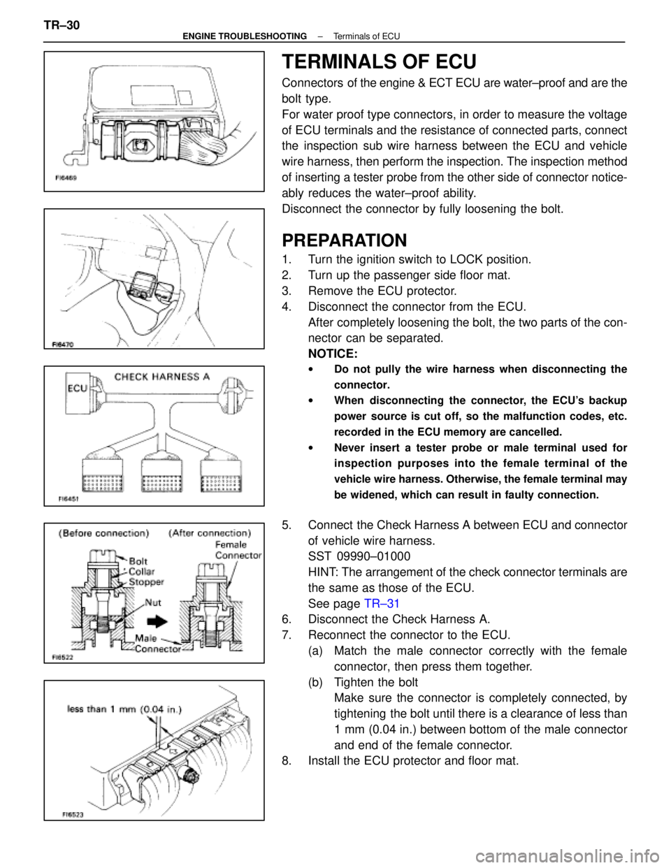
TERMINALS OF ECU
Connectors of the engine & ECT ECU are water±proof and are the
bolt type.
For water proof type connectors, in order to measure the voltage
of ECU terminals and the resistance of connected parts, connect
the inspection sub wire harness between the ECU and vehicle
wire harness, then perform the inspection. The inspection method
of inserting a tester probe from the other side of connector notice-
ably reduces the water±proof ability.
Disconnect the connector by fully loosening the bolt.
PREPARATION
1. Turn the ignition switch to LOCK position.
2. Turn up the passenger side floor mat.
3. Remove the ECU protector.
4. Disconnect the connector from the ECU. After completely loosening the bolt, the two parts of the con-
nector can be separated.
NOTICE:
w Do not pully the wire harness when disconnecting the
connector.
w When disconnecting the connector, the ECU's backup
power source is cut off, so the malfunction codes, etc.
recorded in the ECU memory are cancelled.
w Never insert a tester probe or male terminal used for
inspection purposes into the female terminal of the
vehicle wire harness. Otherwise, the female terminal may
be widened, which can result in faulty connection.
5. Connect the Check Harness A between ECU and connector
of vehicle wire harness.
SST 09990±01000
HINT: The arrangement of the check connector terminals are
the same as those of the ECU.
See page TR±31
6. Disconnect the Check Harness A.
7. Reconnect the connector to the ECU.
(a) Match the male connector correctly with the femaleconnector, then press them together.
(b) Tighten the bolt Make sure the connector is completely connected, by
tightening the bolt until there is a clearance of less than
1 mm (0.04 in.) between bottom of the male connector
and end of the female connector.
8. Install the ECU protector and floor mat.
TR±30
±
ENGINE TROUBLESHOOTING Terminals of ECU
WhereEverybodyKnowsYourName
Page 3412 of 4087
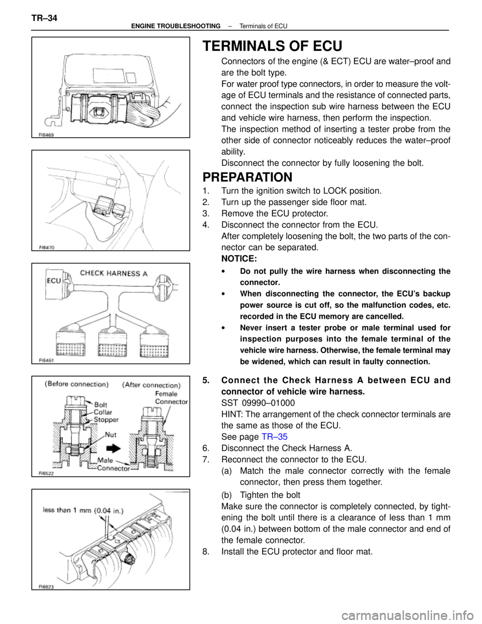
TERMINALS OF ECU
Connectors of the engine (& ECT) ECU are water±proof and
are the bolt type.
For water proof type connectors, in order to measure the volt-
age of ECU terminals and the resistance of connected parts,
connect the inspection sub wire harness between the ECU
and vehicle wire harness, then perform the inspection.
The inspection method of inserting a tester probe from the
other side of connector noticeably reduces the water±proof
ability.
Disconnect the connector by fully loosening the bolt.
PREPARATION
1. Turn the ignition switch to LOCK position.
2. Turn up the passenger side floor mat.
3. Remove the ECU protector.
4. Disconnect the connector from the ECU.After completely loosening the bolt, the two parts of the con-
nector can be separated.
NOTICE:
w Do not pully the wire harness when disconnecting the
connector.
w When disconnecting the connector, the ECU's backup
power source is cut off, so the malfunction codes, etc.
recorded in the ECU memory are cancelled.
w Never insert a tester probe or male terminal used for
inspection purposes into the female terminal of the
vehicle wire harness. Otherwise, the female terminal may
be widened, which can result in faulty connection.
5. Connect the Check Harness A between ECU and
connector of vehicle wire harness.
SST 09990±01000
HINT: The arrangement of the check connector terminals are
the same as those of the ECU.
See page TR±35
6. Disconnect the Check Harness A.
7. Reconnect the connector to the ECU. (a) Match the male connector correctly with the femaleconnector, then press them together.
(b) Tighten the bolt
Make sure the connector is completely connected, by tight-
ening the bolt until there is a clearance of less than 1 mm
(0.04 in.) between bottom of the male connector and end of
the female connector.
8. Install the ECU protector and floor mat.
TR±34
±
ENGINE TROUBLESHOOTING Terminals of ECU
WhereEverybodyKnowsYourName
Page 3616 of 4087
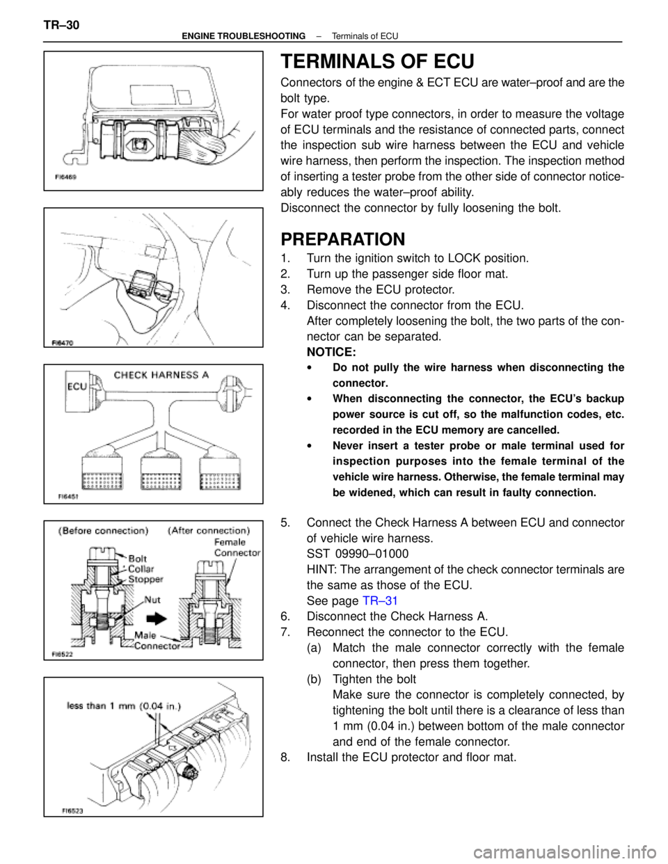
TERMINALS OF ECU
Connectors of the engine & ECT ECU are water±proof and are the
bolt type.
For water proof type connectors, in order to measure the voltage
of ECU terminals and the resistance of connected parts, connect
the inspection sub wire harness between the ECU and vehicle
wire harness, then perform the inspection. The inspection method
of inserting a tester probe from the other side of connector notice-
ably reduces the water±proof ability.
Disconnect the connector by fully loosening the bolt.
PREPARATION
1. Turn the ignition switch to LOCK position.
2. Turn up the passenger side floor mat.
3. Remove the ECU protector.
4. Disconnect the connector from the ECU. After completely loosening the bolt, the two parts of the con-
nector can be separated.
NOTICE:
w Do not pully the wire harness when disconnecting the
connector.
w When disconnecting the connector, the ECU's backup
power source is cut off, so the malfunction codes, etc.
recorded in the ECU memory are cancelled.
w Never insert a tester probe or male terminal used for
inspection purposes into the female terminal of the
vehicle wire harness. Otherwise, the female terminal may
be widened, which can result in faulty connection.
5. Connect the Check Harness A between ECU and connector
of vehicle wire harness.
SST 09990±01000
HINT: The arrangement of the check connector terminals are
the same as those of the ECU.
See page TR±31
6. Disconnect the Check Harness A.
7. Reconnect the connector to the ECU.
(a) Match the male connector correctly with the femaleconnector, then press them together.
(b) Tighten the bolt Make sure the connector is completely connected, by
tightening the bolt until there is a clearance of less than
1 mm (0.04 in.) between bottom of the male connector
and end of the female connector.
8. Install the ECU protector and floor mat.
TR±30
±
ENGINE TROUBLESHOOTING Terminals of ECU
WhereEverybodyKnowsYourName