1991 LEXUS SC300 roof
[x] Cancel search: roofPage 3624 of 4087
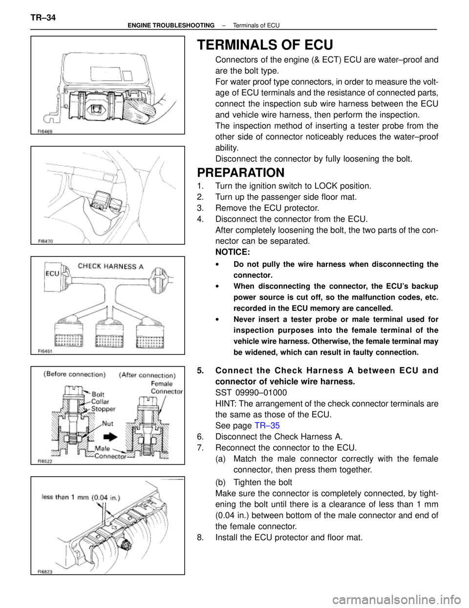
TERMINALS OF ECU
Connectors of the engine (& ECT) ECU are water±proof and
are the bolt type.
For water proof type connectors, in order to measure the volt-
age of ECU terminals and the resistance of connected parts,
connect the inspection sub wire harness between the ECU
and vehicle wire harness, then perform the inspection.
The inspection method of inserting a tester probe from the
other side of connector noticeably reduces the water±proof
ability.
Disconnect the connector by fully loosening the bolt.
PREPARATION
1. Turn the ignition switch to LOCK position.
2. Turn up the passenger side floor mat.
3. Remove the ECU protector.
4. Disconnect the connector from the ECU.After completely loosening the bolt, the two parts of the con-
nector can be separated.
NOTICE:
w Do not pully the wire harness when disconnecting the
connector.
w When disconnecting the connector, the ECU's backup
power source is cut off, so the malfunction codes, etc.
recorded in the ECU memory are cancelled.
w Never insert a tester probe or male terminal used for
inspection purposes into the female terminal of the
vehicle wire harness. Otherwise, the female terminal may
be widened, which can result in faulty connection.
5. Connect the Check Harness A between ECU and
connector of vehicle wire harness.
SST 09990±01000
HINT: The arrangement of the check connector terminals are
the same as those of the ECU.
See page TR±35
6. Disconnect the Check Harness A.
7. Reconnect the connector to the ECU. (a) Match the male connector correctly with the femaleconnector, then press them together.
(b) Tighten the bolt
Make sure the connector is completely connected, by tight-
ening the bolt until there is a clearance of less than 1 mm
(0.04 in.) between bottom of the male connector and end of
the female connector.
8. Install the ECU protector and floor mat.
TR±34
±
ENGINE TROUBLESHOOTING Terminals of ECU
WhereEverybodyKnowsYourName
Page 3813 of 4087
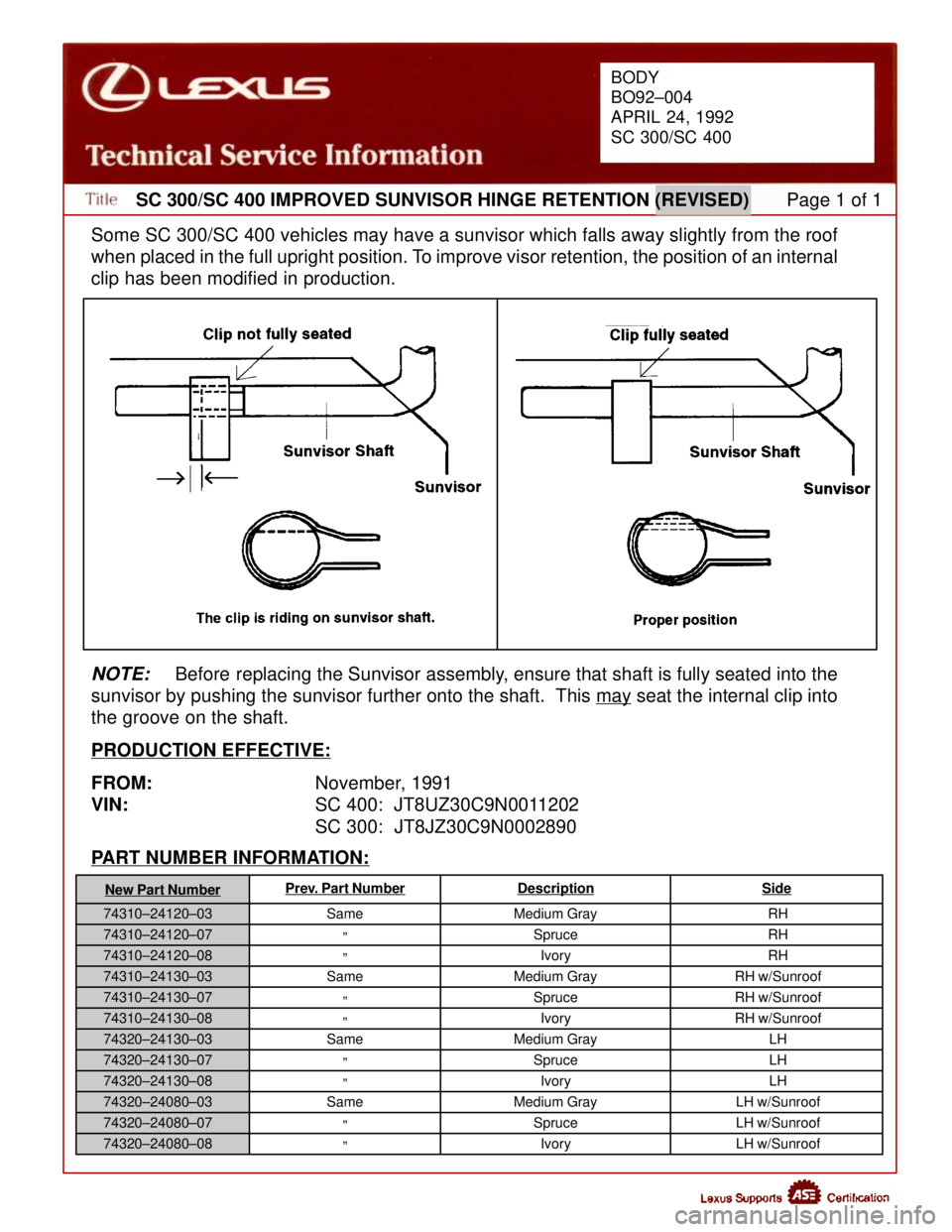
Some SC 300/SC 400 vehicles may have a sunvisor which falls away slightly from the roof
when placed in the full upright position. To improve visor retention, the position of an internal
clip has been modified in production.
BODY
BO92±004
APRIL 24, 1992
SC 300/SC 400
PART NUMBER INFORMATION:
New Part NumberPrev. Part NumberDescriptionSide
NOTE:Before replacing the Sunvisor assembly, ensure that shaft is fully seated into the
sunvisor by pushing the sunvisor further onto the shaft. This may
seat the internal clip into
the groove on the shaft.
PRODUCTION EFFECTIVE:
FROM: November, 1991
VIN: SC 400: JT8UZ30C9N0011202
SC 300: JT8JZ30C9N0002890
Same
º
º
Same
º
º
Same
º
º
Same
º
º Medium Gray
SpruceIvory
SC 300/SC 400 IMPROVED SUNVISOR HINGE RETENTION (REVISED) Page 1 of 1
Medium Gray
SpruceIvory
Medium Gray SpruceIvory
Medium Gray SpruceIvory RH
RH
RH
RH w/Sunroof
RH w/Sunroof
RH w/Sunroof LH
LH
LH
LH w/Sunroof
LH w/Sunroof
LH w/Sunroof
74310±24120±03
74310±24120±07
74310±24120±08
74310±24130±03
74310±24130±07
74310±24130±08
74320±24130±03
74320±24130±07
74320±24130±08
74320±24080±03
74320±24080±07
74320±24080±08
WhereEverybodyKnowsYourName
Page 3873 of 4087

31
Position of Parts in Body
M 1 Mobilephone R 16 Remote Control Mirror LH
M 2 Moon Roof Control Relay R 17 Remote Control Mirror RH
M 3 Moon Roof Control SW R 18 Remote Control Mirror SW
M 4 Moon Roof Motor and Limit SWS 13 Stereo Power Amplifier
O 8 Oxygen Sensor Sub (for California) S 14 Stereo Power Amplifier
P 4 Power Window Control SW RH T 16 Telephone Transceiver and Speaker Relay
P 5 Power Window Master SW and Door Lock Control SW LH T 17 Telephone Transceiver and Speaker Relay
P 6 Power Window Motor LH T 18 Tension Reducer Solenoid LH
P 7 Power Window Motor RH T 19 Tension Reducer Solenoid RH
P 20 Personal Light V 5 Vanity Light LH
R 10 Rear Combination Light LH V 6 Vanity Light RH
R 11 Rear Combination Light RH
R 12 Rear Speaker LH W 8 Wireless Door Lock ECU
R 13 Rear Speaker RH W 9 Woofer Speaker
R 14 Rear Window Defogger (+) W 10 Woofer Speaker Amplifier
R 15 Rear Window Defogger (±)
WhereEverybodyKnowsYourName
Page 3882 of 4087

41
CODEJOINING WIRE HARNESS AND WIRE HARNESS (CONNECTOR LOCATION)
BS1ENGINE ROOM MAIN WIRE AND FLOOR WIRE (LEFT KICK PANEL)
BT1FLOOR WIRE AND COWL WIRE (LEFT KICK PANEL)
BU1INSTRUMENT PANEL WIRE AND FLOOR WIRE (LEFT KICK PANEL)
BV1
BV2FLOOR NO. 3 WIRE AND CONSOLE BOX WIRE (UNDER THE INSTRUMENT PANEL CENTER)
BV3
FLOOR NO. 3 WIRE AND CONSOLE BOX WIRE (UNDER THE INSTRUMENT PANEL CENTER)
BW1ENGINE ROOM MAIN WIRE AND FLOOR NO. 3 WIRE (RIGHT KICK PANEL)
BX1FLOOR NO. 3 WIRE AND COWL WIRE (RIGHT KICK PANEL)
BY1INSTRUMENT PANEL WIRE AND FLOOR NO. 3 WIRE (RIGHT KICK PANEL)
BZ1ROOF WIRE AND MOON ROOF WIRE (FRONT SIDE OF ROOF LEFT)
Bc1FLOOR NO 3 WIRE AND FLOOR WIRE (UNDER THE LEFT SIDE OF REAR SEAT CUSHION)Bc2FLOOR NO. 3 WIRE AND FLOOR WIRE (UNDER THE LEFT SIDE OF REAR SEAT CUSHION)
Bd1FLOOR NO. 3 WIRE AND LUGGAGE NO. 2 WIRE (RIGHT SIDE OF LUGGAGE COMPARTMENT)
WhereEverybodyKnowsYourName
Page 3920 of 4087
237
GLOVE BOX LIGHT SW
CIGARETTE LIGHTER
LUGGAGE COMPARTMENT
DOOR OPENER SW
COMBINATION METER
(EP )
O/D MAIN SW
RHEOSTAT
DO OR LOCK MOTOR,
DOOR UNLOCK
DETECTION SW AND
DOOR OPEN DETECTION
SW LH
MIRROR HEATER LH DOOR KEY LOCK AND
UNLOCK SW LH
POWER WINDOW
MASTER SW
RE MOTE CO NTROL
MIRROR SW
KEY INTER LOCK
SOLENOID
[IGNITION SW]
UNLOCK WA RNING SW
[IGNITION SW]
TURN SIGNAL SW
[COMB. SW]
WIPER AND WASHER SW
[COMB. SW]
LIGHT CONTROL SW
[COMB. SW]
DIMMER SW
[COMB. SW] INTEGRATION RELAY POWER MAIN RELAY HA ZARD S W A/C CONTROL
ASSEMBLY A/T INDICATOR LIGHT
(
FOR SHIFT LEVER )
SEAT HEATER SW TRACTION CUT SW AND
SEAT HEATER SW SHIFT LOCK ECU
3G 8
3F 8
3F 7
3D 10
3D 9
3A 2
1F 6
1K 6 3H
15
3H 14
3H 3
1D 10
1G 3
1G 4
IF
IG 1E
18 3A
1
W±B W±B W±B
W±B
W±B
W±B W±B W±B
W±B W±B
W±B W±B W±B W±B
W±B W±B
W±B W±B
W±B
W±B
W±B
CE NTER AI RB AG
SENSOR ASSEMBLY
I29
W±B
W±B
3G
3
I38 I8 1K 5
WIPER MOTOR
SEAT HEATER RELAY
KICK DOWN SW
THEFT DETERRENT
AND DOOR LOCK ECU
HE ADLIGHT HI RH
HE ADLIGHT HI LH
COMBINATION METER
(
HIGH BEAM )
CRUISE CONTROL SW
[COMB. SW] E3
I1
4
4
1K
12
IE1
11
IH11
CRUISE CONTROL ECU
( GND ) 1J
1
I7
1G1
8
I5 W±B
W±B
W±B
W±B
W±B
W±B
W±B
W±B R
W±B
W±B W±B W±B W±B W±BW±BW±B
W±B W±B W±B
W±B W±B
W±B
W±B
W±B
W±B
W±B W±B
W±B
W±B
IQ1 10
W±B
(E1 )
( E2 )
TILT AND POWER
TELESCOPIC ECU
( GND2 )
W±B ( A/T )
( M/T )
W±B
1H 13
I38
B4
B31
MOO N ROOF CO NTROL
RE LAY
MOON ROOF LIMIT SW
MOO N ROOF MOTOR
MOO N ROOF CO NTROL
SW
PERSONAL LIGHT
VANITY LIGHT LH
VANITY LIGHT RH
PERSONAL LIGHT
VANITY LIGHT RH
VANITY LIGHT LH B3
B1
B1
B2
B
W±B B
W±B
W±B
W±B
W±B
W±B
W±B
W±B W±BW±B
BZ1
4 BZ1
5
B
W±B
W±B
( CANADA )
W±B
( W/O MOON ROOF )(
W/ MOON ROOF )
(
W/O MEMORY MIRROR )
W±B
(
CANADA )
WhereEverybodyKnowsYourName
Page 3923 of 4087
240
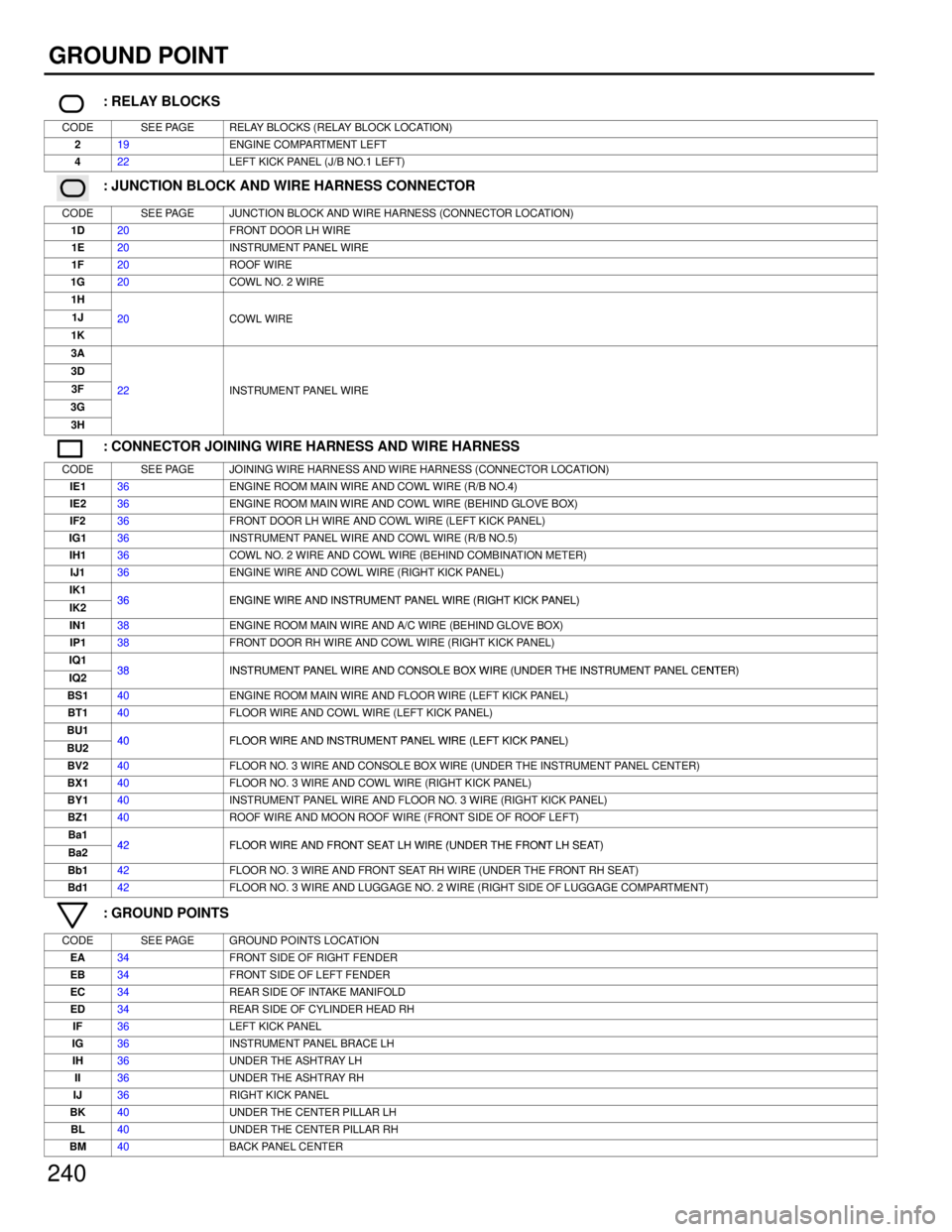
GROUND POINT
: RELAY BLOCKS
CODESEE PAGERELAY BLOCKS (RELAY BLOCK LOCATION)
219ENGINE COMPARTMENT LEFT
422LEFT KICK PANEL (J/B NO.1 LEFT)
: JUNCTION BLOCK AND WIRE HARNESS CONNECTOR
CODESEE PAGEJUNCTION BLOCK AND WIRE HARNESS (CONNECTOR LOCATION)
1D20FRONT DOOR LH WIRE
1E20INSTRUMENT PANEL WIRE
1F20ROOF WIRE
1G20COWL NO. 2 WIRE
1H
1J20COWL WIRE
1K
20COWL WIRE
3A
3D
3F22INSTRUMENT PANEL WIRE
3G
22INSTRUMENT PANEL WIRE
3H
: CONNECTOR JOINING WIRE HARNESS AND WIRE HARNESS
CODESEE PAGEJOINING WIRE HARNESS AND WIRE HARNESS (CONNECTOR LOCATION)
IE136ENGINE ROOM MAIN WIRE AND COWL WIRE (R/B NO.4)
IE236ENGINE ROOM MAIN WIRE AND COWL WIRE (BEHIND GLOVE BOX)
IF236FRONT DOOR LH WIRE AND COWL WIRE (LEFT KICK PANEL)
IG136INSTRUMENT PANEL WIRE AND COWL WIRE (R/B NO.5)
IH136COWL NO. 2 WIRE AND COWL WIRE (BEHIND COMBINATION METER)
IJ136ENGINE WIRE AND COWL WIRE (RIGHT KICK PANEL)
IK136ENGINE WIRE AND INSTRUMENT PANEL WIRE (RIGHT KICK PANEL)IK236ENGINE WIRE AND INSTRUMENT PANEL WIRE (RIGHT KICK PANEL)
IN138ENGINE ROOM MAIN WIRE AND A/C WIRE (BEHIND GLOVE BOX)
IP138FRONT DOOR RH WIRE AND COWL WIRE (RIGHT KICK PANEL)
IQ138INSTRUMENT PANEL WIRE AND CONSOLE BOX WIRE (UNDER THE INSTRUMENT PANEL CENTER)IQ238INSTRUMENT PANEL WIRE AND CONSOLE BOX WIRE (UNDER THE INSTRUMENT PANEL CENTER)
BS140ENGINE ROOM MAIN WIRE AND FLOOR WIRE (LEFT KICK PANEL)
BT140FLOOR WIRE AND COWL WIRE (LEFT KICK PANEL)
BU140FLOOR WIRE AND INSTRUMENT PANEL WIRE (LEFT KICK PANEL)BU240FLOOR WIRE AND INSTRUMENT PANEL WIRE (LEFT KICK PANEL)
BV240FLOOR NO. 3 WIRE AND CONSOLE BOX WIRE (UNDER THE INSTRUMENT PANEL CENTER)
BX140FLOOR NO. 3 WIRE AND COWL WIRE (RIGHT KICK PANEL)
BY140INSTRUMENT PANEL WIRE AND FLOOR NO. 3 WIRE (RIGHT KICK PANEL)
BZ140ROOF WIRE AND MOON ROOF WIRE (FRONT SIDE OF ROOF LEFT)
Ba142FLOOR WIRE AND FRONT SEAT LH WIRE (UNDER THE FRONT LH SEAT)Ba242FLOOR WIRE AND FRONT SEAT LH WIRE (UNDER THE FRONT LH SEAT)
Bb142FLOOR NO. 3 WIRE AND FRONT SEAT RH WIRE (UNDER THE FRONT RH SEAT)
Bd142FLOOR NO. 3 WIRE AND LUGGAGE NO. 2 WIRE (RIGHT SIDE OF LUGGAGE COMPARTMENT)
: GROUND POINTS
CODESEE PAGEGROUND POINTS LOCATION
EA34FRONT SIDE OF RIGHT FENDER
EB34FRONT SIDE OF LEFT FENDER
EC34REAR SIDE OF INTAKE MANIFOLD
ED34REAR SIDE OF CYLINDER HEAD RH
IF36LEFT KICK PANEL
IG36INSTRUMENT PANEL BRACE LH
IH36UNDER THE ASHTRAY LH
II36UNDER THE ASHTRAY RH
IJ36RIGHT KICK PANEL
BK40UNDER THE CENTER PILLAR LH
BL40UNDER THE CENTER PILLAR RH
BM40BACK PANEL CENTER
WhereEverybodyKnowsYourName
Page 3924 of 4087
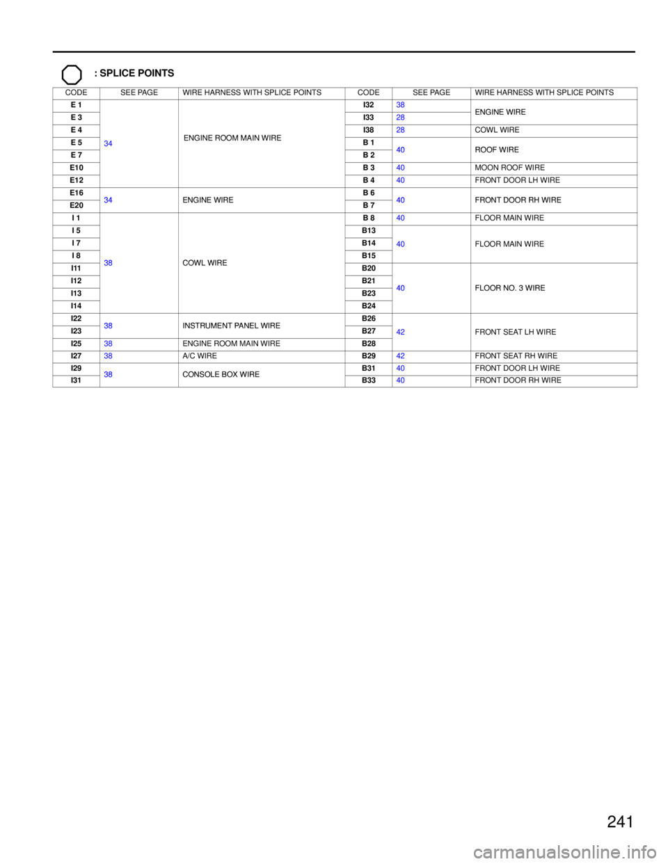
241
: SPLICE POINTS
CODESEE PAGEWIRE HARNESS WITH SPLICE POINTSCODESEE PAGEWIRE HARNESS WITH SPLICE POINTS
E 1I3238ENGINE WIREE 3I3328ENGINE WIRE
E 4ENGINE ROOM MAIN WIREI3828COWL WIRE
E 534ENGINE ROOM MAIN WIREB 140ROOF WIREE 7
34
B 240ROOF WIRE
E10B 340MOON ROOF WIRE
E12B 440FRONT DOOR LH WIRE
E1634ENGINE WIREB 640FRONT DOOR RH WIREE2034ENGINE WIREB 740FRONT DOOR RH WIRE
I 1B 840FLOOR MAIN WIRE
I 5B13
I 7B1440FLOOR MAIN WIRE
I 838COWL WIREB15
40FLOOR MAIN WIRE
I1138COWL WIREB20
I12B2140FLOOR NO 3 WIREI13B2340FLOOR NO. 3 WIRE
I14B24
I2238INSTRUMENT PANEL WIREB26
I2338INSTRUMENT PANEL WIREB2742FRONT SEAT LH WIRE
I2538ENGINE ROOM MAIN WIREB28
42FRONT SEAT LH WIRE
I2738A/C WIREB2942FRONT SEAT RH WIRE
I2938CONSOLE BOX WIREB3140FRONT DOOR LH WIRE
I3138CONSOLE BOX WIREB3340FRONT DOOR RH WIRE
WhereEverybodyKnowsYourName
Page 3941 of 4087
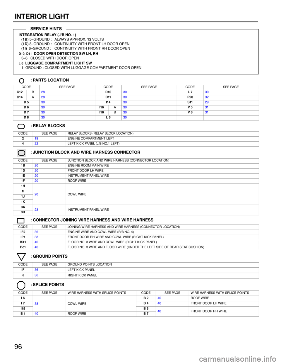
96
INTERIOR LIGHT
INTEGRATION RELAY (J/B NO. 1)(1B) 5±GROUND : ALWAYS APPROX. 12 VOLTS
(1D) 8±GROUND : CONTINUITY WITH FRONT LH DOOR OPEN
(1I) 6±GROUND : CONTINUITY WITH FRONT RH DOOR OPEN
D10, D11 DOOR OPEN DETECTION SW LH, RH
3±6 : CLOSED WITH DOOR OPEN
L 6 LUGGAGE COMPARTMENT LIGHT SW
1±GROUND : CLOSED WITH LUGGAGE COMPARTMENT DOOR OPEN
: PARTS LOCATION
CODESEE PAGECODESEE PAGECODESEE PAGE
C12B28D1030L 730
C14A28D1130P2032
D 530I1430S1129
D 630I16A30V 531
D 730I16B30V 631
D 830L 630
: RELAY BLOCKS
CODESEE PAGERELAY BLOCKS (RELAY BLOCK LOCATION)
219ENGINE COMPARTMENT LEFT
422LEFT KICK PANEL (J/B NO.1 LEFT)
: JUNCTION BLOCK AND WIRE HARNESS CONNECTOR
CODESEE PAGEJUNCTION BLOCK AND WIRE HARNESS (CONNECTOR LOCATION)
1B20ENGINE ROOM MAIN WIRE
1D20FRONT DOOR LH WIRE
1E20INSTRUMENT PANEL WIRE
1F20ROOF WIRE
1H
1I20COWL WIRE1J20COWL WIRE
1K
3A23INSTRUMENT PANEL WIRE3D23INSTRUMENT PANEL WIRE
: CONNECTOR JOINING WIRE HARNESS AND WIRE HARNESS
CODESEE PAGEJOINING WIRE HARNESS AND WIRE HARNESS (CONNECTOR LOCATION)
IF236ENGINE WIRE AND COWL WIRE (R/B NO. 4)
IP138FRONT DOOR RH WIRE AND COWL WIRE (RIGHT KICK PANEL)
BX140FLOOR NO. 3 WIRE AND COWL WIRE (RIGHT KICK PANEL)
Bc140FLOOR NO. 3 WIRE AND FLOOR WIRE (UNDER THE LEFT SIDE OF REAR SEAT CUSHION)
: GROUND POINTS
CODESEE PAGEGROUND POINTS LOCATION
IF36LEFT KICK PANEL
IJ36RIGHT KICK PANEL
: SPLICE POINTS
CODESEE PAGEWIRE HARNESS WITH SPLICE POINTSCODESEE PAGEWIRE HARNESS WITH SPLICE POINTS
I 6B 240ROOF WIRE
I 738COWL WIREB 440FRONT DOOR LH WIRE
I15
38COWL WIRE
B 640FRONT DOOR RH WIREB 140ROOF WIREB 740FRONT DOOR RH WIRE
SERVICE HINTS
WhereEverybodyKnowsYourName