Page 3385 of 4087
Diagnosis Inspection (Test Mode)
Compared to the normal mode, the test mode has high sensing
ability to detect malfunctions.
It can also detect malfunctions in the starter signal circuit, the IDL
contact signal of the throttle position sensor, air conditioner signal
and neutral start switch signal.
Furthermore, the same diagnostic items which are detected in the
normal mode can also be detected in the test mode.
DIAGNOSTIC CODE CHECK
1. Initial conditions.(a) Battery voltage 11 V or more.
(b) Throttle valve fully closed (throttle position sensor IDLpoints closed).
(c) Transmission in neutral position.
(d) Air conditioner switched off.
2. Turn ignition switch off.
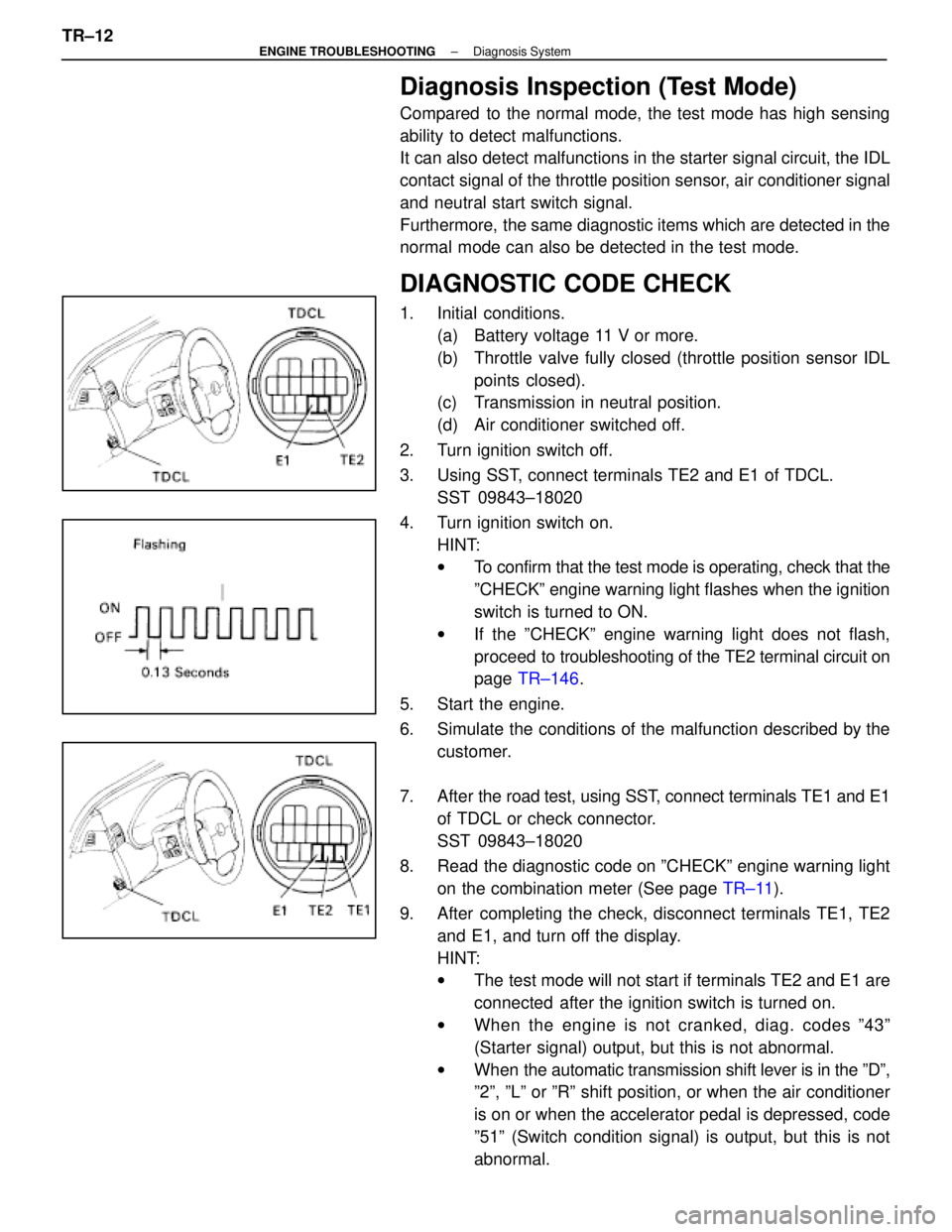
3. Using SST, connect terminals TE2 and E1 of TDCL. SST 09843±18020
4. Turn ignition switch on. HINT:
wTo confirm that the test mode is operating, check that the
ºCHECKº engine warning light flashes when the ignition
switch is turned to ON.
w If the ºCHECKº engine warning light does not flash,
proceed to tro ubleshooting of the TE2 terminal circuit on
page TR±146 .
5. Start the engine.
6. Simulate the conditions of the malfunction described by the customer.
7. After the road test, using SST, connect terminals TE1 and E1
of TDCL or check connector.
SST 09843±18020
8. Read the diagnostic code on ºCHECKº engine warning light on the combination meter (See page TR±11).
9. After completing the check, disconnect terminals TE1, TE2 and E1, and turn off the display.
HINT:
wThe test mode will not start if terminals TE2 and E1 are
connected after the ignition switch is turned on.
w When the engine is not cranked, diag. codes º43º
(Starter signal) output, but this is not abnormal.
w When the automatic transmission shift lever is in the ºDº,
º2º, ºLº or ºRº shift position, or when the air conditioner
is on or when the accelerator pedal is depressed, code
º51º (Switch condition signal) is output, but this is not
abnormal.
TR±12
±
ENGINE TROUBLESHOOTING Diagnosis System
WhereEverybodyKnowsYourName
Page 3388 of 4087
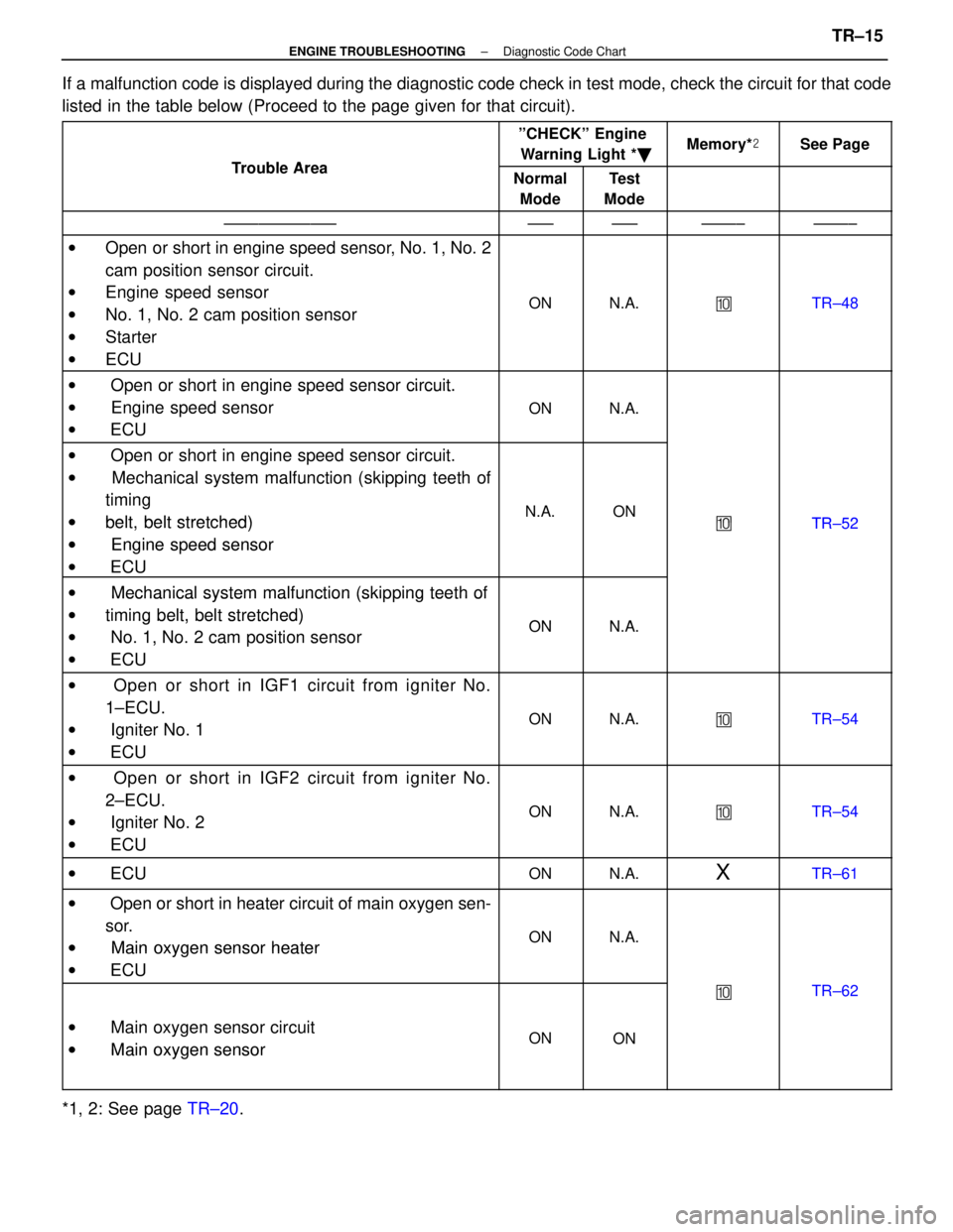
If a malfunction code is displayed during the diagnostic code check in tes\
t mode, check the circuit for that code
listed in the table below (Proceed to the page given for that circuit).
Tro ble Area
ºCHECKº EngineWarning Light * �Memory*�See Page
Trouble AreaNormal
ModeTest
Mode
±±±±±±±±±±±±±±±±±±±±±±±±±±±±±
w Open or short in engine speed sensor, No. 1, No. 2
cam position sensor circuit.
w Engine speed sensor
w No. 1, No. 2 cam position sensor
w Starter
w ECU
ONN.A.�TR±48
w Open or short in engine speed sensor circuit.w Oen or short in engine s eed sensor circuit.
w Engine speed sensor
ONN.A. Engine s eed sensor
w ECU
ONN.A.
w Open or short in engine speed sensor circuit.g
w Mechanical system malfunction (skipping teeth of
ti itiming
wbelt belt stretched)N.A.ON�TR 52wbelt, belt stretched)
wEngine speed sensor
�TR±52
w Engine s eed sensor
w ECU
w Mechanical system malfunction (skipping teeth ofw Mechanical system malfunction (ski ing teeth of
wtiming belt, belt stretched)ONNAwtiming belt, belt stretched)
w No. 1, No. 2 cam position sensorONN.A. No. 1, No. 2 cam osition sensor
w ECU
w Open or short in IGF1 circuit from igniter No.
1±ECU.
w Igniter No. 1
w ECU
ONN.A.�TR±54
w Open or short in IGF2 circuit from igniter No.
2±ECU.
w Igniter No. 2
w ECU
ONN.A.�TR±54
w ECUONN.A.XTR±61
w Open or short in heater circuit of main oxygen sen-
sor.
w Main oxygen sensor heaterONN.A.w Main oxygen sensor heater
w ECU
�TR±62
w Main oxygen sensor circuit
w
Main oxygen sensorONONw Main oxygen sensor
*1, 2: See page TR±20.
±
ENGINE TROUBLESHOOTING Diagnostic Code ChartTR±15
WhereEverybodyKnowsYourName
Page 3393 of 4087
DIAGNOSTIC CODE CHART (Cont'd)
*1: ºONº displayed in the diagnosis mode column indicates that the º\
CHECKº Engine Warning Light islighted up when a malfunction is detected. ºOFFº indicates that the ºC\
HECKº does not light up during
malfunction diagnosis, even if a malfunction is detected. ºN.A.º i\
ndicates that the item is not included
in malfunction diagnosis.
*2: ºOº in the memory column indicates that a diagnostic code is reco\
rded in the ECU memory when a mal- function occurs. ºXº indicates that a diagnostic code is not recor\
ded in the ECU memory even if a mal-
function occurs. Accordingly, output of diagnostic results in normal or test mode is performed with \
the
IG switch ON.
*3: Only for USA specification vehicles.
TR±20
±
ENGINE TROUBLESHOOTING Diagnostic Code Chart
WhereEverybodyKnowsYourName
Page 3397 of 4087
YESNO
NOYES
YES
NO
OKNG
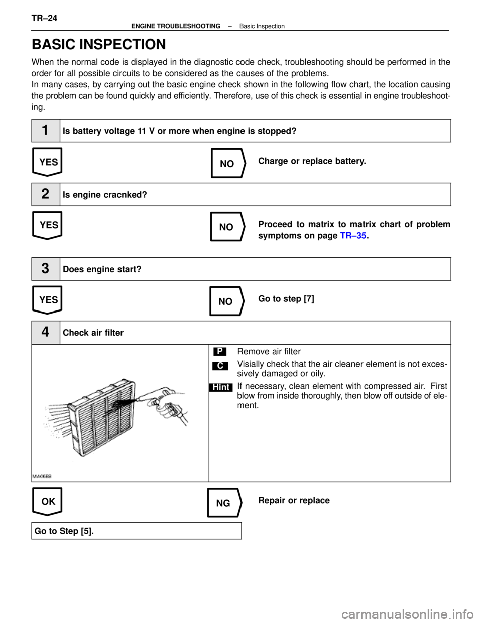
BASIC INSPECTION
When the normal code is displayed in the diagnostic code check, troubleshoot\
ing should be performed in the
order for all possible circuits to be considered as the causes of the pr\
oblems.
In many cases, by carrying out the basic engine check shown in the follo\
wing flow chart, the location causing
the problem can be found quickly and ef ficiently. Therefore, use of this check is essential in engine troubleshoot-
ing.
1Is battery voltage 11 V or more when engine is stopped?
Charge or replace battery.
2Is engine cracnked?
Proceed to matrix to matrix chart of problem
symptoms on page TR±35.
3Does engine start?
Go to step [7]
4Check air filter
C
Hint
PRemove air filter
Visially check that the air cleaner element is not exces-
sively damaged or oily.
If necessary, clean element with compressed air. First
blow from inside thoroughly, then blow off outside of ele-
ment.
Repair or replace
Go to Step [5].
TR±24±
ENGINE TROUBLESHOOTING Basic Inspection
WhereEverybodyKnowsYourName
Page 3449 of 4087
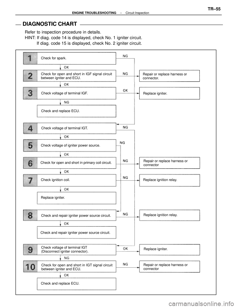
DIAGNOSTIC CHART
DIAGNOSTIC
CHART
Refer to inspection procedure in details.
HINT: If diag. code 14 is displayed, check No. 1 igniter circuit. If diag. code 15 is displayed, check No. 2 igniter circuit.
Check for spark.
Check for open and short in IGF signal circuit
between igniter and ECU.
Check voltage of terminal IGF.
Check and replace ECU.
Check voltage of terminal IGT.
Check voltage of igniter power source.
Check for open and short in primary coil circuit.
Check ignition coil.
Replace igniter.
Check and repair igniter power source circuit.
Check voltage of terminal IGT
(Disconnect igniter connector).
Check and repair igniter power source circuit. Repair or replace harness or
connector.
Replace igniter.
Repair or replace harness or
connector
Replace ignition relay.
Replace ignition relay.
Check for open and short in IGT signal circuit
between igniter and ECU.
Check and replace ECU. Repair or replace harness or
connectorReplace igniter.
±
ENGINE TROUBLESHOOTING Circuit InspectionTR±55
WhereEverybodyKnowsYourName
Page 3450 of 4087
OKNG
OKNG
OKNG
INSPECTION PROCEDURE
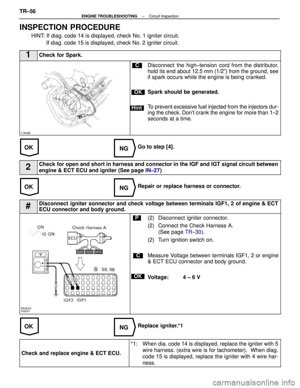
HINT: If diag. code 14 is displayed, check No. 1 igniter circuit. If diag. code 15 is displayed, check No. 2 igniter circuit.
1Check for Spark.
C
OK
Hint
Disconnect the high±tension cord from the distributor,
hold its end about 12.5 mm (1/2º) from the ground, see
if spark occurs while the engine is being cranked.
Spark should be generated.
To prevent excessive fuel injected from the injectors dur-
ing the check. Don't crank the engine for more than 1±2
seconds at a time.
Go to step [4].
2Check for open and short in harness and connector in the IGF and IGT signal c\
ircuit between
engine & ECT ECU and igniter (See page IN±27)
Repair or replace harness or connector.
#Disconnect igniter sonnector and check voltage between terminals IGF1, 2 of engine & ECT
ECU connector and body ground.
C
OK
P(2) Disconnect igniter connector.
(2) Connect the Check Harness A.
(See page TR±30).
(2) Turn ignition switch on.
Measure Voltage between terminals IGF1, 2 or engine
& ECT ECU connector and body ground.
Voltage: 4 ± 6 V
Replace igniter.*1
Check and replace engine & ECT ECU.
*1: When dia. code 14 is displayed, replace the igniter with 5 wire harness. (extra wire is for tachometer). When diag.
code 15 is displayed, replace the igniter with 4 wire har-
ness.
TR±56±
ENGINE TROUBLESHOOTING Circuit Inspection
WhereEverybodyKnowsYourName
Page 3452 of 4087
OKNG
OKNG
6Check for open and short in harness and connector between ignition relay and \
ignition coil,
ignition coil and igniter (See page IN±27).
Repair or replace harness or connector
#Check ignition coil.
C
OK
PDisconnect ignition coil connector.
(For No. 1 ignition coil (on left bank), remove the battery)
(2) Check primary coil. Measure resistance between terminals of ignition
coil connector.
(2) Check secondary coil. Measure resistance between terminal 1 of ignition
coil connector and high±tension terminal.
Replace ignition coil.
Replace Igniter. *1
*1: When diag. code 14 is displayed, replace the igniter with 5 wire harness. (extra wire is for tachometer). When diag.
code 15 is displayed, replace the igniter with 4 wire har-
ness
TR±58±
ENGINE TROUBLESHOOTING Circuit Inspection
WhereEverybodyKnowsYourName
Page 3454 of 4087
NGOK
OKNG
9Disconnect igniter connector and check voltage between terminals IGT1, 2 of engine & ECT
ECU connector and body ground.
C
OK
PDisconnect igniter connector.
Connect engine & ECT ECU connector.
Measure voltage between terminals IGT1, 2 of engine
& ECT ECU connector and body ground when engine
is cranked.
Voltage: 0.5 ± 1.0 V(Neither 0 V nor 5 V)
Replace igniter .*1
10Check for Open and short in harness and connector in IGT signal circuit betwee\
n engine & ECT
ECU and igniter (See page IN±27).
Repair or replace harness or connector.
Check and replace engine & ECT ECU.
*1: When diag. code 14 is displayed, replace the igniter with 5 wire harness. (extra wire is for tachometer). When diag.
code 15 is displayed, replace the igniter with 4 wire har-
ness
TR±60±
ENGINE TROUBLESHOOTING Circuit Inspection
WhereEverybodyKnowsYourName