Page 118 of 4087
Check power transistor.
(1) Remove cooling unit (See page BO-107).
(2) Disconnect power transistor connector.
(1) Check test bulb lights up when battery and
resistor are connected to power transistor
connector as left illustration shows.
(2) Measure resistance between terminal 2 and 3
(1) The bulb lights up.
(2)Resistance: 2.0± 2.4 ��k �
Replace power transistor.
Check for open and short in harness and connector between air
conditioner control assembly and power transistor (See page IN-27).
Repair or replace harness or connector.
Proceed to next circuit inspection shown on matrix
chart (See page AC-36).
INSPECTION PROCEDURE
±
AIR CONDITIONING SYSTEM TroubleshootingAC±79
WhereEverybodyKnowsYourName
Page 297 of 4087

MEASURE ACCUMULATOR BACK PRESSURE
AT0QU±01
NOTICE:
�Perform the test at normal operating fluid temperature 50±80 �C (122±176 �F).
� Be careful to prevent the oil pressure gauge hose from interfering with \
the exhaust pipe.
(a) Warm up the transmission fluid.
(b) Remove the test plug on the transmission case rear right side and connec\
t the oil pressure gauge SST.
SST 09992±00094
HINT: Connecting the oil pressure gauge will be made easier by moving the RH \
side head insulator aside.
(c) Remove the passenger side No.2 under cover and ECM protector.
(d) Connect the SST (check harness A) between ECM and connector of vehicle\
wire harness.
SST: 09990±01000
(e) Install one test lead probe into the terminal SLN of the ECM wire harnes\
s side connector and take care not to ground the other test lead probe.
HINT: Prepare test leads which are connected with an (approximately) 8 W l\
ight bulb.
AT±56
±
A304E (1UZ±FE) AUTOMATIC TRANSMISSION TROUBLESHOOTING
WhereEverybodyKnowsYourName
Page 324 of 4087

OKNG
INSPECTION PROCEDURE
1Check No. 4 solenoid valve.
C
OK
P
C
OK
C
OK
C
OK
Check solenoid resistance
1. Jack up the Vehicle
2. Remove the oil pan.
3. Disconnect the connector
Measure resistance between terminals 1 and 2 of sole-
noid connector.
Resistance: 5.1 ± 5.5 �
Check solenoid operation
Connect positive � lead with an 8±10 W bulb to terminal
1 of solenoid connector and negative � lead to terminal
2, then check the movement of the valve.
Reference
Check the solenoid's operation
1. Prepare a variable power supply.
2. Connect positive ��lead of the variable power
supply to terminal 1 of solenoid connector and neg-
ative � lead to terminal 2.
3. Check the movement of the valve when the voltage is gradually increased. (A current greater than 1 A
should not be supplied.)
As the voltage is increased, the valve should move slow-
ly in the direction.
4. Check the movement of the valve when the voltage is cut off.
The valve should return in the direction.
Replace No. 4 solenoid valve.
Go to step �.
AT±84±
A304E (1UZ±FE) AUTOMATIC TRANSMISSION TROUBLESHOOTING
WhereEverybodyKnowsYourName
Page 336 of 4087

OKNG
INSPECTION PROCEDURE
1Check No. 3 solenoid valve.
C
OK
P
C
OK
C
OK
C
OK
Check solenoid resistance
1. Jack up the vehicle.
2. Remove oil pan.
3. Disconnect solenoid connector.
Measure resistance between terminals 1 and 2 of sole-
noid connector.
Resistance: 3.5 ± 3.9 �
Check solenoid operation
Connect positive � lead with an 8 ± 10 W bulb to termi-
nal 1 of solenoid connector and negative � lead to ter-
minal 2, then check the movement of the valve.
Reference
Check solenoid operation
1. Prepare a variable power supply.
2. Connect positive � lead of the variable power sup-
ply to terminal 1 of solenoid connector and negative
� lead to terminal 2.
3. Check the movement of the valve when the voltage is gradually increased. (A current greater than 1 A
should not be supplied.)
As the voltage is increased, the valve should move
slowly in the direction.
4. Check the movement of the valve when the voltage is cut off.
The valve should return in the direction.
Replace No. 3 solenoid valve.
Go to step �.
AT±96±
A304E (1UZ±FE) AUTOMATIC TRANSMISSION TROUBLESHOOTING
WhereEverybodyKnowsYourName
Page 537 of 4087

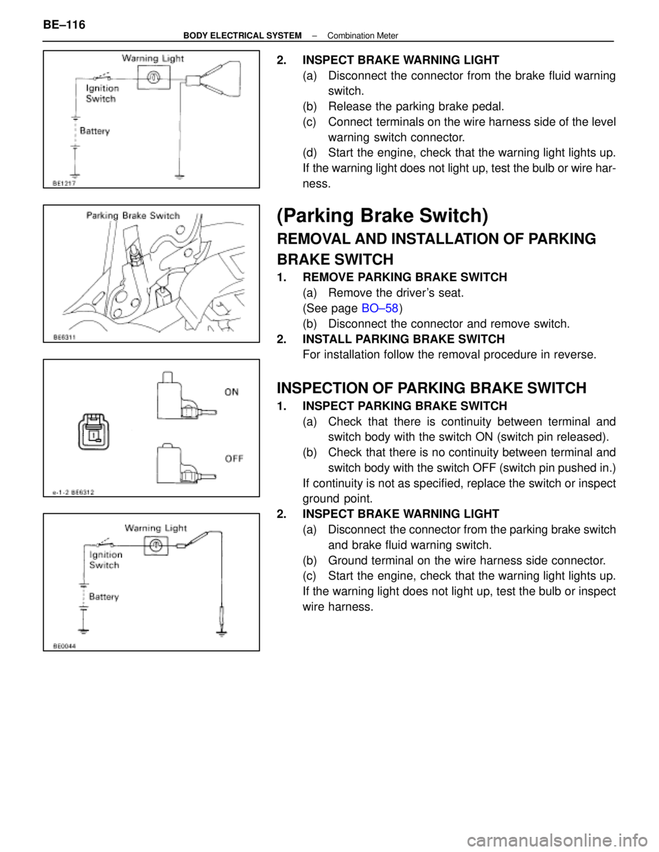
2. INSPECT BRAKE WARNING LIGHT(a) Disconnect the connector from the brake fluid warningswitch.
(b) Release the parking brake pedal.
(c) Connect terminals on the wire harness side of the level warning switch connector.
(d) Start the engine, check that the warning light lights up.
If the warning light does not light up, test the bulb or wire har-
ness.
(Parking Brake Switch)
REMOVAL AND INSTALLATION OF PARKING
BRAKE SWITCH
1. REMOVE PARKING BRAKE SWITCH
(a) Remove the driver's seat.
(See page BO±58)
(b) Disconnect the connector and remove switch.
2. INSTALL PARKING BRAKE SWITCH For installation follow the removal procedure in reverse.
INSPECTION OF PARKING BRAKE SWITCH
1. INSPECT PARKING BRAKE SWITCH
(a) Check that there is continuity between terminal andswitch body with the switch ON (switch pin released).
(b) Check that there is no continuity between terminal and switch body with the switch OFF (switch pin pushed in.)
If continuity is not as specified, replace the switch or inspect
ground point.
2. INSPECT BRAKE WARNING LIGHT (a) Disconnect the connector from the parking brake switchand brake fluid warning switch.
(b) Ground terminal on the wire harness side connector.
(c) Start the engine, check that the warning light lights up.
If the warning light does not light up, test the bulb or inspect
wire harness.
BE±116
±
BODY ELECTRICAL SYSTEM Combination Meter
WhereEverybodyKnowsYourName
Page 538 of 4087

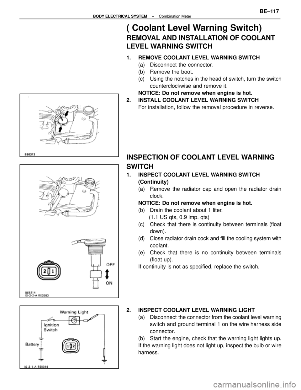
( Coolant Level Warning Switch)
REMOVAL AND INSTALLATION OF COOLANT
LEVEL WARNING SWITCH
1. REMOVE COOLANT LEVEL WARNING SWITCH(a) Disconnect the connector.
(b) Remove the boot.
(c) Using the notches in the head of switch, turn the switchcounterclockwise and remove it.
NOTICE: Do not remove when engine is hot.
2. INSTALL COOLANT LEVEL WARNING SWITCH For installation, follow the removal procedure in reverse.
INSPECTION OF COOLANT LEVEL WARNING
SWITCH
1. INSPECT COOLANT LEVEL WARNING SWITCH(Continuity)
(a) Remove the radiator cap and open the radiator drainclock.
NOTICE: Do not remove when engine is hot.
(b) Drain the coolant about 1 liter. (1.1 US qts, 0.9 lmp. qts)
(c) Check that there is continuity between terminals (float down).
(d) Close radiator drain cock and fill the cooling system with
coolant.
(e) Check that there is no continuity between terminals (float up).
If continuity is not as specified, replace the switch.
2. INSPECT COOLANT LEVEL WARNING LIGHT (a) Disconnect the connector from the coolant level warning
switch and ground terminal 1 on the wire harness side
connector.
(b) Start the engine, check that the warning light lights up.
If the warning light does not light up, inspect the bulb or wire
harness.
±
BODY ELECTRICAL SYSTEM Combination MeterBE±117
WhereEverybodyKnowsYourName
Page 558 of 4087
Wiring and Connector Diagrams
Parts Inspection
(Defogger Switch)
REMOVAL AND INSTALLATION OF AIR
CONDITIONER CONTROL PANEL
ASSEMBLY
(See Instrument Panel on page BO±111)
INSPECTION OF DEFOGGER SWITCH
INSPECT SWITCH OPERATION
(a) Connect the positive (+) lead from the battery to terminal
A6 and negative (±) lead to terminal A7.
(b) Connect the positive (+) lead from the battery to terminal
B10 through a 1.4 W test bulb.
BE±172
±
BODY ELECTRICAL SYSTEM Defogger System
WhereEverybodyKnowsYourName
Page 559 of 4087

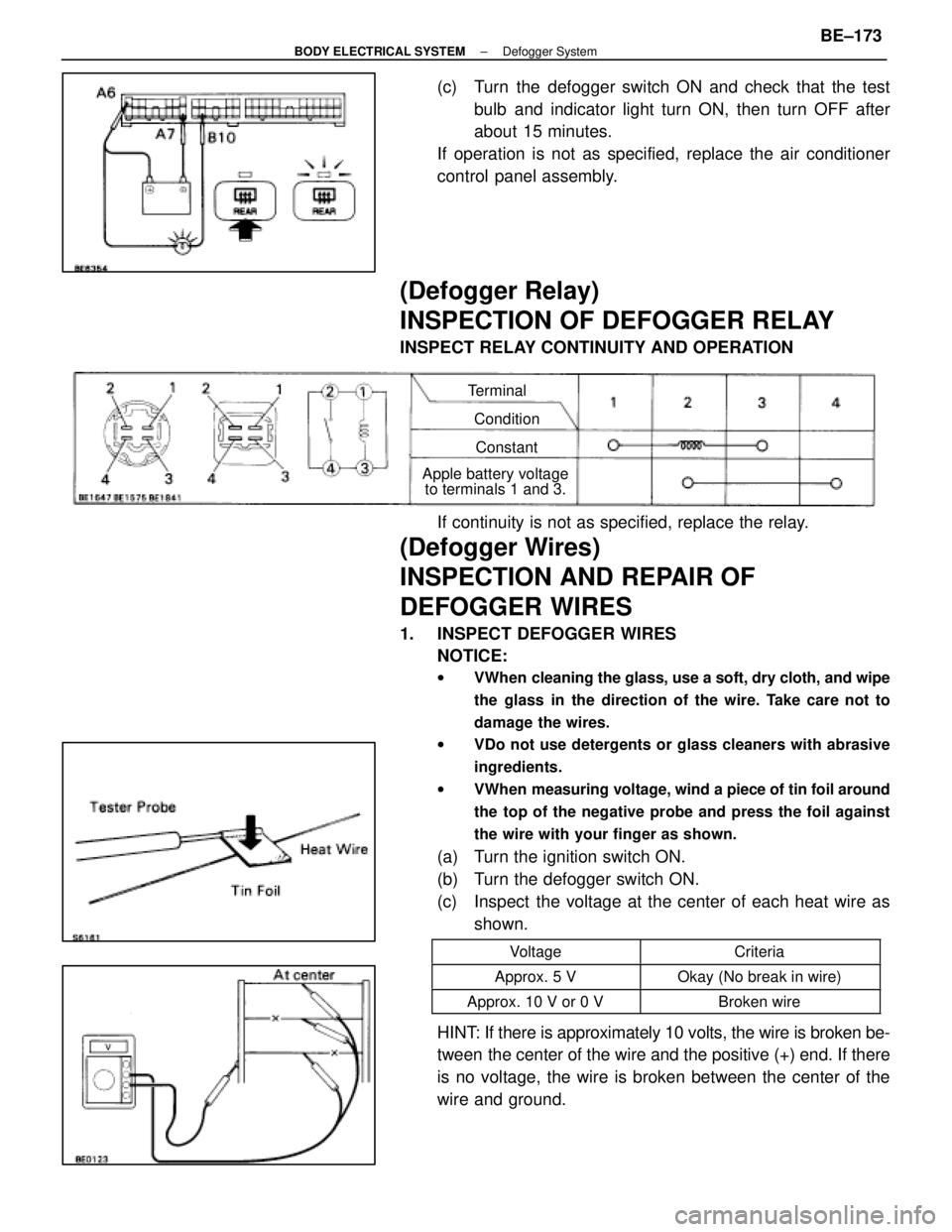
(c) Turn the defogger switch ON and check that the testbulb and indicator light turn ON, then turn OFF after
about 15 minutes.
If operation is not as specified, replace the air conditioner
control panel assembly.
(Defogger Relay)
INSPECTION OF DEFOGGER RELAY
INSPECT RELAY CONTINUITY AND OPERATION
Terminal
ConditionConstant
Apple battery voltage to terminals 1 and 3.
If continuity is not as specified, replace the relay.
(Defogger Wires)
INSPECTION AND REPAIR OF
DEFOGGER WIRES
1. INSPECT DEFOGGER WIRES
NOTICE:
w VWhen cleaning the glass, use a soft, dry cloth, and wipe
the glass in the direction of the wire. Take care not to
damage the wires.
w VDo not use detergents or glass cleaners with abrasive
ingredients.
w VWhen measuring voltage, wind a piece of tin foil around
the top of the negative probe and press the foil against
the wire with your finger as shown.
(a) Turn the ignition switch ON.
(b) Turn the defogger switch ON.
(c) Inspect the voltage at the center of each heat wire as
shown.
VoltageCriteria
Approx. 5 VOkay (No break in wire)
Approx. 10 V or 0 VBroken wire
HINT: If there is approximately 10 volts, the wire is broken be-
tween the center of the wire and the positive (+) end. If there
is no voltage, the wire is broken between the center of the
wire and ground.
±
BODY ELECTRICAL SYSTEM Defogger SystemBE±173
WhereEverybodyKnowsYourName