Page 849 of 4087
 Turn the defogger switch ON and check that the test bulb andindicator light turn ON, then turn OFF after about 15 minutes.
If operation is not as specified, replace the air conditioner control
p")
(c) Turn the defogger switch ON and check that the test bulb andindicator light turn ON, then turn OFF after about 15 minutes.
If operation is not as specified, replace the air conditioner control
panel assembly.
(Defogger Relay)
INSPECTION OF DEFOGGER RELAY
INSPECT RELAY CONTINUITY AND OPERATION
If continuity is not as specified, replace the relay.
(Defogger Wires)
INSPECTION AND REPAIR OF
DEFOGGER WIRES
1. INSPECT DEFOGGER WIRESNOTICE:
w When cleaning the glass, use a soft, dry cloth, and wipe
the glass in the direction of the wire. Take care not to
damage the wires.
w Do not use detergents or glass cleaners with abrasive
ingredients.
w When measuring voltage, wind a piece of tin foil around
the top of the negative probe and press the foil against
the wire with your finger as shown.
(a) Turn the ignition switch ON.
(b) Turn the defogger switch ON.
(c) Inspect the voltage at the center of each heat wire as
shown.
���������� ����������Voltage���������� ����������Criteria
����������Approx. 5 V����������Okay (No break in wire)���������� ����������Approx. 10 V or 0 V���������� ����������Broken wire
HINT: If there is approximately 10 volts, the wire is broken be-
tween the center of the wire and the positive (+) end. If there
is no voltage, the wire is broken between the center of the
wire and ground.
±
BODY ELECTRICAL SYSTEM Defogger SystemBE±53
WhereEverybodyKnowsYourName
Page 852 of 4087

Description ± Taillight System
The component parts of this system and their function are as shown in the f\
ollowing table.
�������� ��������Parts Name������������������\
��������")
(TAILLIGHT SYSTEM)
Description ± Taillight System
The component parts of this system and their function are as shown in the f\
ollowing table.
�������� ��������Parts Name������������������\
����������� ������������������\
�����������Function
�������� �
�������
��������
Light Control Switch������������������\
����������� �
������������������\
����������
������������������\
�����������
Grounds current from the taillight control relay via the integration rel\
ay, switching each relay
and supplying current to the appropriate bulbs accordance with the switc\
h position.
�������� ��������Taillight Control Relay������������������\
����������� ������������������\
�����������Turned on by signals from the light control switch and supplies current t\
o each bulb.
�������� �
�������
�
�������
��������
Integration Relay
������������������\
����������� �
������������������\
����������
�
������������������\
����������
������������������\
�����������
Carries out ºLight Auto Turn±Offº of the headlights, fog lights and taillights and cuts off cur-
rent to the light control switch in accordance with signals from the GAU\
GE fuse and door
courtesy switch.
�������� �
�������
��������
Light Failure Sensor������������������\
����������� �
������������������\
����������
������������������\
�����������
This sensor senses when a bulb in rear combination light is burnt out an\
d lights up a warning
light.
��������Integration Relay������������������\
������������������� ��������Integration Relay
(Daytime Running
������������������\
����������� ������������������\
�����������
Refer to
BE±30.�������� ��������(y g
Light Relay: CANADA)������������������\
����������� ������������������\
�����������
PARTS LOCATION ± Taillight System
±
BODY ELECTRICAL SYSTEM Lighting SystemBE±53
WhereEverybodyKnowsYourName
Page 857 of 4087

Troubleshooting
Taillight System
You will find the cause of troubles more easily using the table well shown \
below. In this table, the numbers indi-
cate the order priority of the causes in troubles. Check each part in the o\
rder shown. If necessary, replace the
parts.
See page
BE±4,20BE±20 ,57BE±46BE±49BE±62BE±79BE±4,20
±
BE±6
±
Trouble
Part name
TAIL FuseTaillignt Control RelayLight Control SwitchIntegration RelayLight Failure SensorDoor CourtesyGAUGE FuseWire HarnessBulbOther Parts
Taillight does not light. (Headlight does
not light.) 12 3
SA
Taillight does not light. (Headlight is
normal.)12345
US
A
Only one light does not light. (Taillight) 2 1 U
Rear combination light does not light. 213
ªLight Auto Turn±Off Systemº does
not operate. 1432
Taillight does not light. (Headlight is
does not light.) 123
Taillight does not light. (Headlight is
normal.)12345
Only one light does not light. (Taillight) 21
ARear combination light does not light. 213
ANADA
ªLight Auto Turn±Off Systemº does
not operate. 1423
CA
N
Taillight does not light with light control
SW in TAIL123
Taillight does not go out with light
control SW in OFF1324
Headlight and Taillight do not light with
engine running and light control SW in
OFF
213*14
*1:
Alternator
L
Terminal
BE±58±
BODY ELECTRICAL SYSTEM Lighting System
WhereEverybodyKnowsYourName
Page 858 of 4087
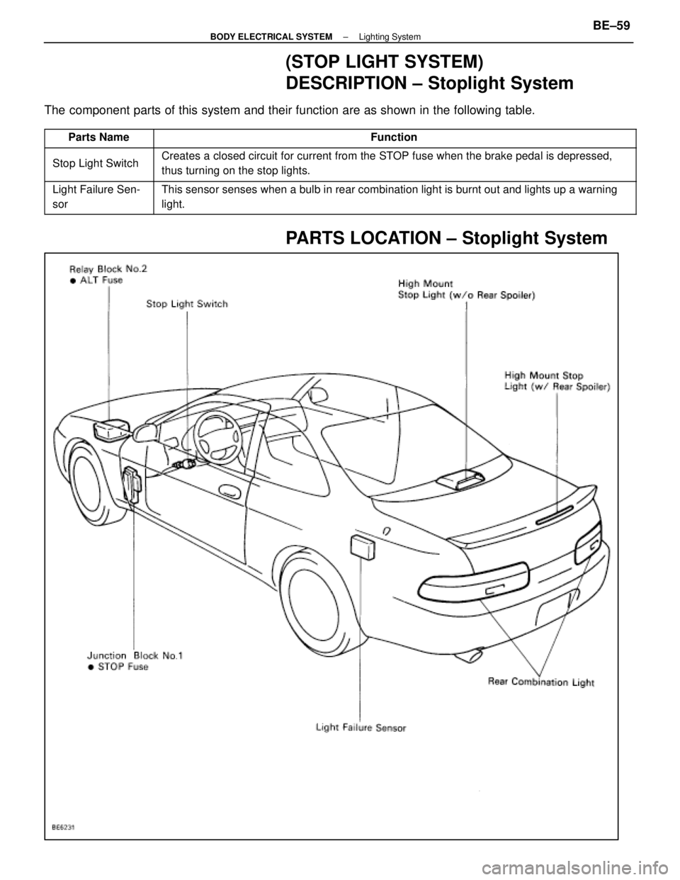
(STOP LIGHT SYSTEM)
DESCRIPTION ± Stoplight System
The component parts of this system and their function are as shown in the f\
ollowing table.
������� �������Parts Name������������������\
������������ ������������������\
������������Function
������� �
������
�������Stop Light Switch
������������������\
������������ �
������������������\
�����������
������������������\
������������
Creates a closed circuit for current from the STOP fuse when the brake pedal is depressed,
thus turning on the stop lights.
������� �
������
�������
Light Failure Sen-
sor������������������\
������������ �
������������������\
�����������
������������������\
������������
This sensor senses when a bulb in rear combination light is burnt out an\
d lights up a warning
light.
PARTS LOCATION ± Stoplight System
±
BODY ELECTRICAL SYSTEM Lighting SystemBE±59
WhereEverybodyKnowsYourName
Page 862 of 4087

Disconnect the connector from the sensor and inspect the
connector on the wire harness side as shown.
Check forTester")
INSPECTION OF LIGHT FAILURE
SENSOR
INSPECT LIGHT FAILURE SENSOR(Relay Circuit)
Disconnect the connector from the sensor and inspect the
connector on the wire harness side as shown.
Check forTester connectionConditionSpecified value
Continuity1±GroundConstant*Continuity
2±GroundConstant*Continuity
3±GroundConstant*Continuity
9±GroundConstant*Continuity
11±GroundConstantContinuity
Voltage3±GroundTail or HeadOFFNo voltage
ONBattery voltage
4±GroundIgnition switchLOCK or ACCNo voltage
ONBattery voltage
7±GroundStop light switchOFFNo voltage
ONBattery voltage
Voltage8±GroundIgnition switchLOCK or ACCNo voltage
ONBattery voltage
*: There is resistance because this circuit is grounded through the bulb*: There is resistance because this circuit is grounded through the bulb.
If circuit is as specified, replace the sensor. If the circuit is not
as specified, refer to BE±60 wiring diagram and inspect the
circuits connected to other parts.
±
BODY ELECTRICAL SYSTEM Lighting SystemBE±63
WhereEverybodyKnowsYourName
Page 863 of 4087
Troubleshooting
Stop Light System
You will find the cause of trouble more easily using the table shown. In t\
his table, the numbers indicate the order
priority of the causes in trouble. Check each part in the order shown. If nece\
ssary, replace the parts.
See pagePart
name
Trouble
Stop light does not light up.
Stop light always lights up.
Only one light always lights up.
Only one light does not light up.
BE±4
, 20
BE±61
BE±62
BE±6
STOP Fuse
Stop Light Switch
Light Failure Sensor
Wire Harness
Bulb
BE±64±
BODY ELECTRICAL SYSTEM Lighting System
WhereEverybodyKnowsYourName
Page 867 of 4087

(Combination Switch Assembly)
(See page BE±39)
HINT: Inspect turn signal light switch.
(Turn Signal Flasher)
REMOVAL AND INSTALLATION OF TURN
SIGNAL FLASHER
(S")
Parts Inspection (Turn and Hazard)
(Combination Switch Assembly)
(See page BE±39)
HINT: Inspect turn signal light switch.
(Turn Signal Flasher)
REMOVAL AND INSTALLATION OF TURN
SIGNAL FLASHER
(See page BE±16 )
INSPECTION OF TURN SIGNAL
FLASHER
INSPECT TURN SIGNAL FLASHER
(Operation)
LHD Side
(a) Connect the positive (+) lead from the battery to terminal
1 and the negative (±) lead to 4.
(b) Connect the two turn signal light bulbs parallel to each other to terminals 3 and 4, check that bulbs flash.
RHD Side
(c) Connect the positive (+) lead from the battery to terminal
1 and the negative (±) lead to 2.
(d) Connect two turn signal light bulbs parallel to each other
to terminals 2 and 5, check that the bulbs flash.
HINT: The turn signal lights should flash 60 to 120 times per
minute.
If one of the front or rear turn signal lights has an open circuit,
the number of flashes will be more than 140 per minute.
If operation is not as specified, replace the flasher.
(Flasher Circuit)
(See page BE±23 )
(HAZARD WARNING SWITCH)
REMOVAL AND INSTALLATION OF
HAZARD WARNING SWITCH
1. REMOVE INSTRUMENT PANEL NO.2 REGISTER
ASSEMBLY
(See page BO±111 )
2. REMOVE HAZARD WARNING SWITCH Remove two screws and hazard warning switch from register.
3. INSTALL HAZARD WARNING SWITCH AND REGISTER
For installation, follow the removal procedure in reverse.
BE±68
±
BODY ELECTRICAL SYSTEM Lighting System
WhereEverybodyKnowsYourName
Page 868 of 4087

Inspect the switch continuity between terminals.
If continuity is not as specified, replace the switch.
(Switch Circui")
INSPECTION OF HAZARD WARNING
SWITCH
INSPECTION HAZARD WARNING SWITCH(Continuity)
Inspect the switch continuity between terminals.
If continuity is not as specified, replace the switch.
(Switch Circuit)
Disconnect the switch connector and inspect the connection
on the wire harness side as shown.
Check forTester connectionConditionSpecified value
Voltage8±GroundConstantBattery positive voltage
10±GroundIgnition switchpositionLOCK or ACCNo voltage10±GroundIgnition switch positionONBattery positive voltage
*12±GroundLight control switchpositionOFFNo voltage*12±GroundLight control switch positionTAIL or HEADBattery voltage
Continuity*13±GroundConstantContinuity
5±GroundConstant*2Continuity
6±GroundConstant*2Continuity
*1: Illumination*2: There is resistance because this circuit is grounded through the bulb.\
If the circuit is not as specified, refer to BE±66 wiring diagram
and inspect the circuits connected to other parts.
±
BODY ELECTRICAL SYSTEM Lighting SystemBE±69
WhereEverybodyKnowsYourName