1991 LEXUS SC300 display
[x] Cancel search: displayPage 3722 of 4087
NGOK
INSPECTION PROCEDURE
HINT:
wIf diag. code 41 is displayed, check throttle position sensor circuit. If \
diag. code 47 is displayed, check
sub±throttle position sensor circuit.
w If diag. codes º22º (water temperature sensor circuit), º24º\
(intake air temperature sensor circuit) and º41º
(throttle position sensor circuit) are output simultaneously, E2 (sensor ground) may be open.
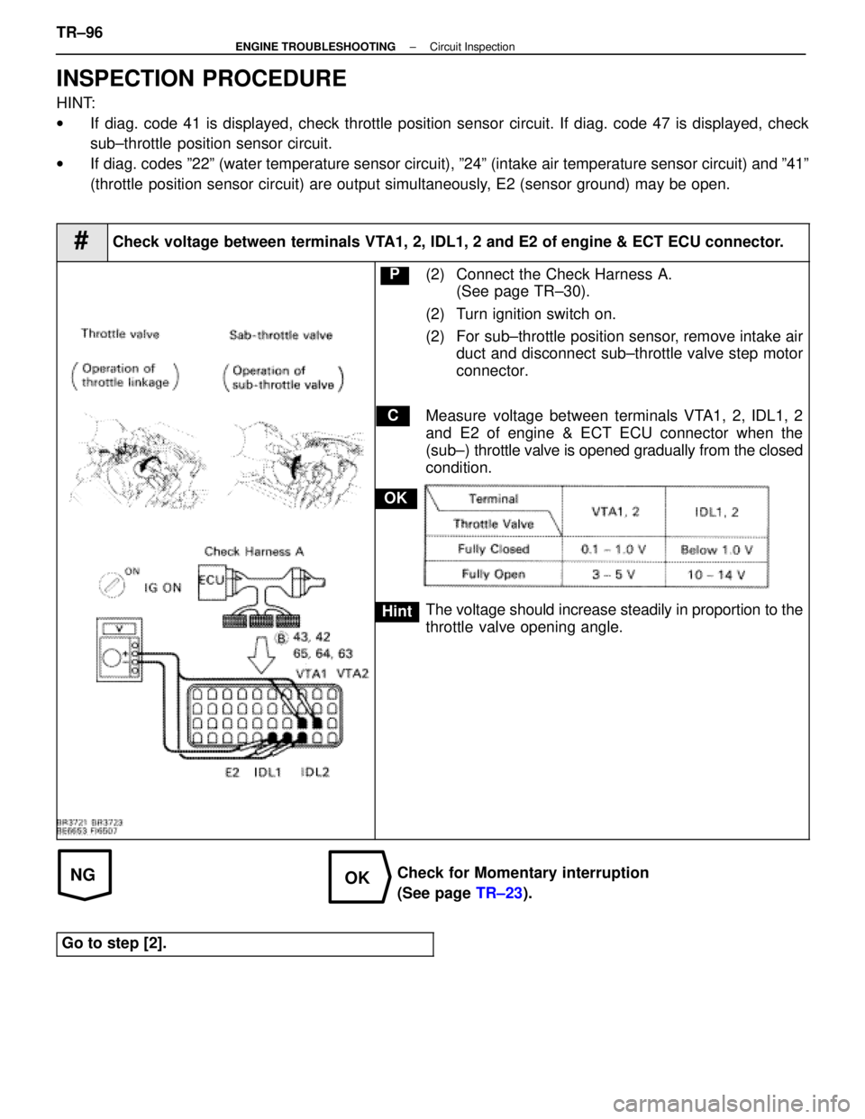
#Check voltage between terminals VTA1, 2, IDL1, 2 and E2 of engine & ECT ECU connector.
C
OK
Hint
P(2) Connect the Check Harness A.
(See page TR±30).
(2) Turn ignition switch on.
(2) For sub±throttle position sensor, remove intake air duct and disconnect sub±throttle valve step motor
connector.
Measure voltage between terminals VTA1, 2, IDL1, 2
and E2 of engine & ECT ECU connector when the
(sub±) throttle valve is opened gradually from the closed
condition.
The voltage should increase steadily in proportion to the
throttle valve opening angle.
Check for Momentary interruption
(See page TR±23).
Go to step [2].
TR±96±
ENGINE TROUBLESHOOTING Circuit Inspection
WhereEverybodyKnowsYourName
Page 3727 of 4087
OKNG
OKNG
1Check operation of speedometer.
Drive the vehicle and check if the operation of the speedometer in the c\
ombination meter is normal.
The No. 1 speed sensor is operating normally if the speedometer display is \
normal.C
Hint
Check speedometer circuit. See combination meter trou-
bleshooting on page BE±131.
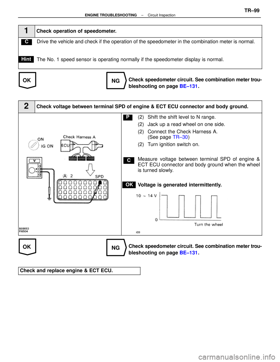
2Check voltage between terminal SPD of engine & ECT ECU connector and bod\
y ground.
C
OK
P(2) Shift the shift level to N range.
(2) Jack up a read wheel on one side.
(2) Connect the Check Harness A.
(See page TR±30)
(2) Turn ignition switch on.
Measure voltage between terminal SPD of engine &
ECT ECU connector and body ground when the wheel
is turned slowly.
Voltage is generated intermittently.
Check speedometer circuit. See combination meter trou-
bleshooting on page BE±131.
Check and replace engine & ECT ECU.
±
ENGINE TROUBLESHOOTING Circuit InspectionTR±99
WhereEverybodyKnowsYourName
Page 3732 of 4087
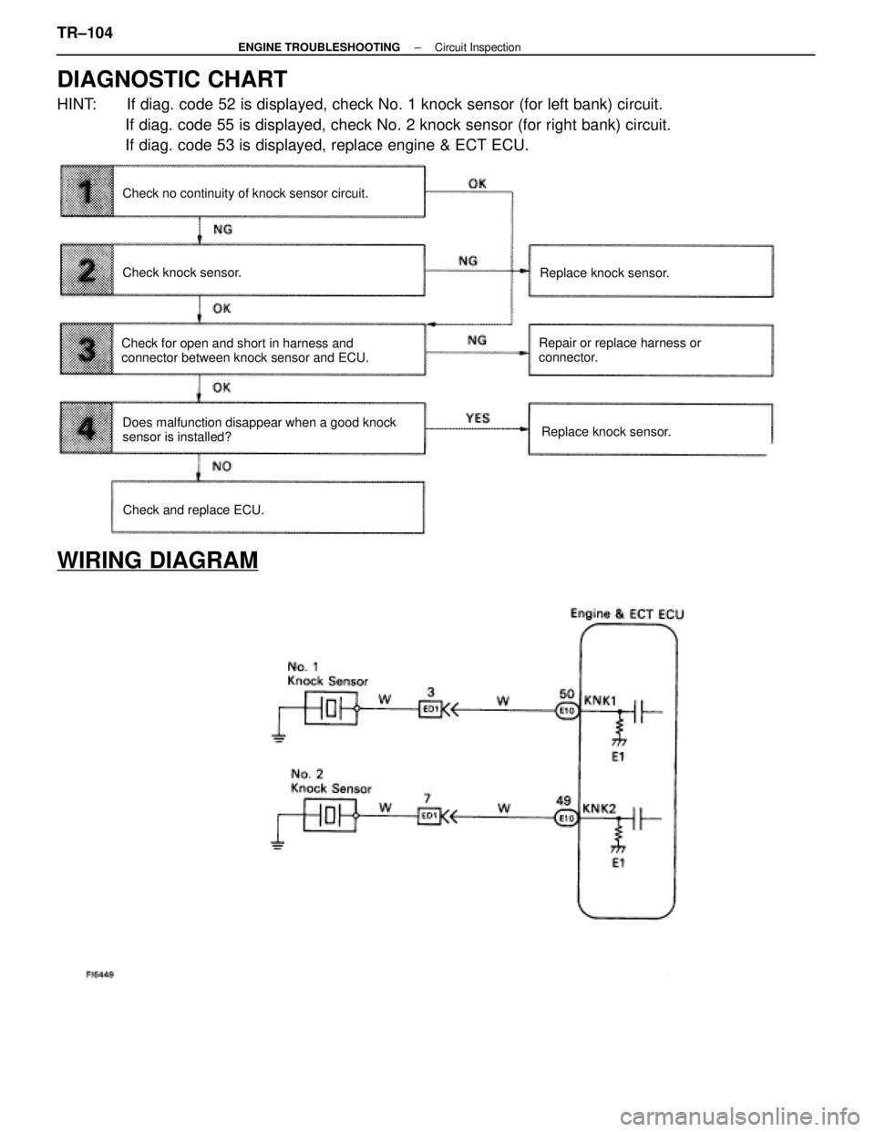
DIAGNOSTIC CHART
HINT: If diag. code 52 is displayed, check No. 1 knock sensor (for left bank)\
circuit.If diag. code 55 is displayed, check No. 2 knock sensor (for right bank\
) circuit.
If diag. code 53 is displayed, replace engine & ECT ECU.
Does malfunction disappear when a good knock
sensor is installed? Repair or replace harness or
connector.
Replace knock sensor.
Check no continuity of knock sensor circuit.
Check knock sensor.
Check for open and short in harness and
connector between knock sensor and ECU.
Replace knock sensor.
Check and replace ECU.
WIRING DIAGRAM
TR±104±
ENGINE TROUBLESHOOTING Circuit Inspection
WhereEverybodyKnowsYourName
Page 3770 of 4087
DATE:JULY 19, 1996
Title1992 - 1995 SC 300/400 A/C CONTROL ASSEMBLY SERVICE PARTSPage 1 of 6
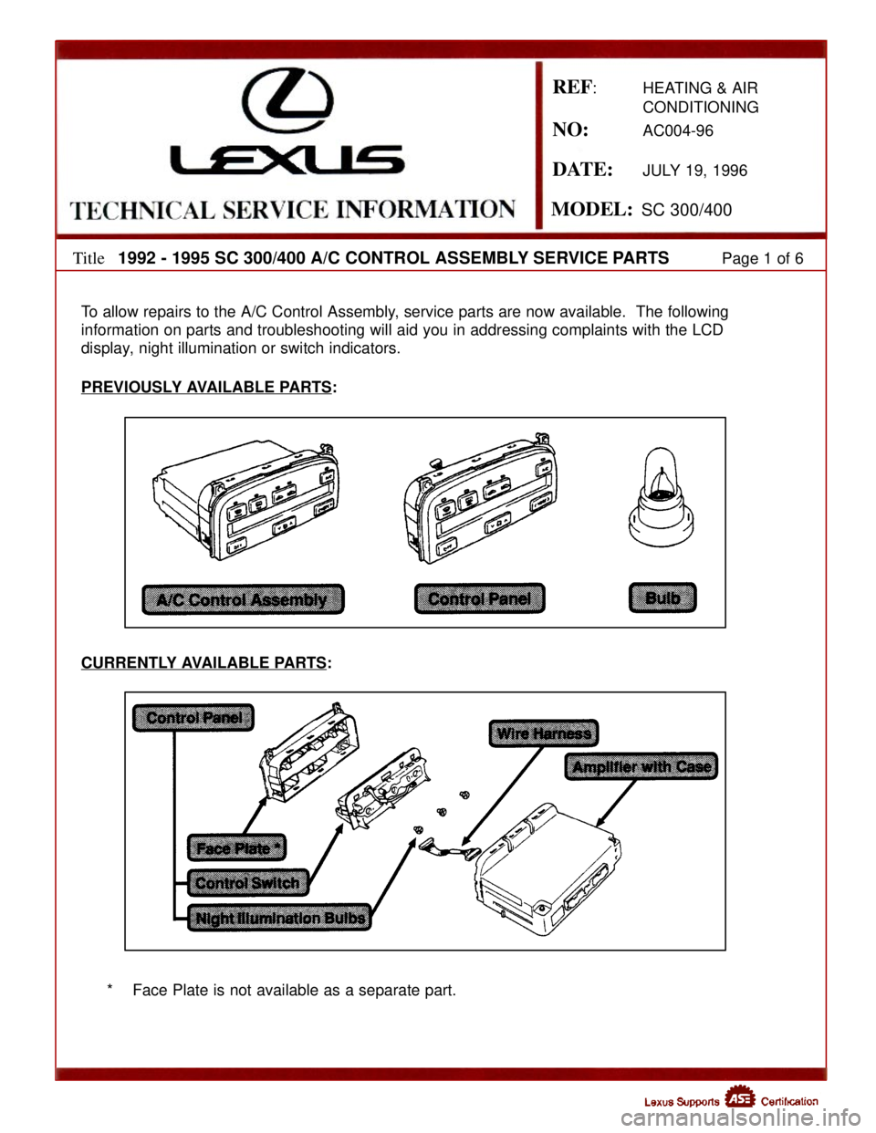
To allow repairs to the A/C Control Assembly, service parts are now available. The following
information on parts and troubleshooting will aid you in addressing comp\
laints with the LCD
display, night illumination or switch indicators.
PREVIOUSLY AVAILABLE PARTS
:
CURRENTLY AVAILABLE PARTS
:
* Face Plate is not available as a separate part.
REF: HEATING & AIR CONDITIONING
NO:AC004-96
MODEL:SC 300/400
WhereEverybodyKnowsYourName
Page 3902 of 4087

67
2. CONTROL SYSTEM
*EFI (ELECTRONIC FUEL INJECTION) SYSTEM
THE EFI SYSTEM MONITORS THE ENGINE CONDITION THROUGH THE SIGNALS INPUT FROM EACH SENSOR (IN\
PUT SIGNALS
FROM (1) TO (13) ETC.) TO THE ECU. THE BEST FUEL INJECTION TIMING IS DECIDED BASED ON THIS DATA AND THE PROGRAM
MEMORIZED BY THE ECU, AND THE CONTROL SIGNAL IS OUTPUT TO TERMINALS #10, #20, #30, #40, #50 AND #60 OF THE ECU TO
OPERATE THE INJECTOR. (INJECT THE FUEL). THE EFI SYSTEM PRODUCES CONTROL OF FUEL INJECTION OPERATION BY THE
ECU IN RESPONSE TO THE DRIVING CONDITIONS.
* ESA (ELECTRONIC SPARK ADVANCE) SYSTEM
THE ESA SYSTEM MONITORS THE ENGINE CONDITION THROUGH THE SIGNALS INPUT TO THE ECU FROM EACH SENSOR (INPUT
SIGNALS FROM (1), (2), (4) TO (13) ETC.). THE BEST IGNITION TIMING IS DECIDED ACCORDING TO THIS DATA AND THE
MEMORIZED DATA IN THE ECU AND THE CONTROL SIGNAL IS OUTPUT TO TERMINAL IGT THIS SIGNAL CONTROLS THE IGNITER
TO PROVIDE THE BEST IGNITION TIMING FOR THE DRIVING CONDITIONS.
* OXYGEN SENSOR HEATER CONTROL SYSTEM (USA SPEC.)
THE OXYGEN SENSOR HEATER CONTROL SYSTEM TURNS THE HEATER ON WHEN THE INTAKE AIR VOLUME IS LOW (TEMP. OF
EXHAUST EMISSIONS IS LOW), AND WARMS UP THE OXYGEN SENSOR TO IMPROVE DETECTION PERFORMANCE OF THE
SENSOR.
THE ECU EVALUATES THE SIGNALS FROM EACH SENSOR (INPUT SIGNALS FROM (1), (2), (4)\
, (9) TO (11) ETC.,) AND OUTPUTS
CURRENT TO TERMINAL HT TO CONTROL THE HEATER.
* ISC (IDLE SPEED CONTROL) SYSTEM
THE ISC SYSTEM (STEP MOTOR TYPE) INCREASES THE RPM AND PROVIDES IDLING STABILITY FOR FAST IDLE±UP WHEN THE
ENGINE IS COLD, AND WHEN THE IDLE SPEED HAS DROPPED DUE TO ELECTRICAL LOAD AND SO ON. THE ECU EVALUATES
THE SIGNALS FROM EACH SENSOR (INPUT SIGNALS FROM (1), (4), (5), (8)\
, (9), (11) ETC.), OUTPUTS CURRENT TO TERMINAL ISC1,
ISC2, ISC3 AND ISC4 TO CONTROL ISC VALVE.
* EGR CONTROL SYSTEM
THE EGR CONTROL SYSTEM DETECTS THE SIGNAL FROM EACH SENSOR (INPUT SIGNALS \
FROM (1), (4), (9), (10) ETC.), AND
OUTPUTS CURRENT TO TERMINAL EGR TO CONTROL THE EGR VALVE.
* FUEL PUMP CONTROL SYSTEM
THE COMPUTER OUTPUTS CURRENT TO TERMINAL FPC AND CONTROLS THE FUEL PUMP ECU AND FUEL PUMP DRIVE SPEED
IN RESPONSE TO CONDITIONS.
* ACIS (ACOUSTIC CONTROL INDUCTION SYSTEM)
ACIS INCLUDES A VALVE IN THE BULKHEAD SEPARATING THE SURGE TANK INTO TWO PARTS. THIS VALE IS OPENED AND
CLOSED IN ACCORDANCE WITH THE DRIVING CONDITIONS TO CONTROL THE INTAKE MANIFOLD LENGTH IN TWO STAGES FOR
INCREASED ENGINE OUTPUT IN ALL RANGES FROM LOW TO HIGH SPEEDS.
THE ECU JUDGES THE VEHICLE SPEED BY THE SIGNALS ((4), (5)) FROM EACH \
SENSOR AND OUTPUTS SIGNALS TO THE
TERMINAL ACIS TO CONTROL THE VSV (FOR OPENING AND CLOSING THE INTAKE CONTROL VALVE).
3. DIAGNOSIS SYSTEM
WITH THE DIAGNOSIS SYSTEM, WHEN THERE IS A MALFUNCTION IN THE ECU SIGNAL\
SYSTEM, THE MALFUNCTIONING SYSTEM IS
RECORDED IN THE MEMORY. THE MALFUNCTIONING SYSTEM CAN BE FOUND BY READING THE CODE DISPLAYED BY THE
CHECKING ENGINE WARNING LIGHT.
4. FAIL±SAFE SYSTEM
WHEN A MALFUNCTION HAS OCCURRED IN ANY SYSTEM, IF THERE IS A POSSIBILITY OF \
ENGINE TROUBLE BEING CAUSED BY
CONTINUED CONTROL BASED ON THE SIGNALS FROM THAT SYSTEM, THE FAIL±SAFE SYSTEM EITHER CONTROLS THE SYSTEM
BY USING DATA (STANDARD VALUES) RECORDED IN THE ECU MEMORY OR ELSE STOPS THE ENGINE.
NOTE: THE SPECIFICATION DESCRIPTIONS ªUSA SPEC.º AND ªEXC. USA SPEC.º USED IN THIS SECTION INDICATE THE
FOLLOWING SPECIFICATIONS.
USA SPEC. : USA (50 STATES) SPECIFICATIONS
EXC. USA SPEC. : USA (EXCEPT CALIFORNIA) AND CANADIAN SPECIFICATIONS.
WhereEverybodyKnowsYourName
Page 3917 of 4087
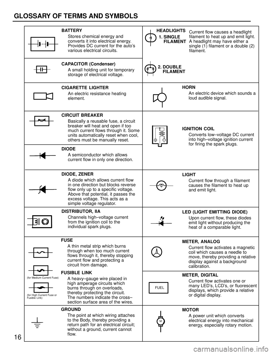
METER, ANALOGCurrent flow activates a magnetic
coil which causes a needle to
move, thereby providing a relative
display against a background
calibration.
LED (LIGHT EMITTING DIODE)
Upon current flow, these diodes
emit light without producing the
heat of a comparable light.
IGNITION COIL
Converts low±voltage DC current
into high±voltage ignition current
for firing the spark plugs.
1. SINGLE
FILAMENT
GROUND
The point at which wiring attaches
to the Body, thereby providing a
return path for an electrical circuit;
without a ground, current cannot
flow. Current flow causes a headlight
filament to heat up and emit light.
A headlight may have either a
single (1) filament or a double (2)
filament.
BATTERY
Stores chemical energy and
converts it into electrical energy.
Provides DC current for the auto's
various electrical circuits.
CAPACITOR (Condenser) A small holding unit for temporary
storage of electrical voltage.
CIRCUIT BREAKER Basically a reusable fuse, a circuit
breaker will heat and open if too
much current flows through it. Some
units automatically reset when cool,
others must be manually reset.
DIODE A semiconductor which allows
current flow in only one direction.
DIODE, ZENER A diode which allows current flow
in one direction but blocks reverse
flow only up to a specific voltage.
Above that potential, it passes the
excess voltage. This acts as a
simple voltage regulator.
FUSE A thin metal strip which burns
through when too much current
flows through it, thereby stopping
current flow and protecting a
circuit from damage.
FUSIBLE LINK A heavy±gauge wire placed in
high amperage circuits which
burns through on overloads,
thereby protecting the circuit.
The numbers indicate the cross±
section surface area of the wires. HORN
An electric device which sounds a
loud audible signal.
LIGHT Current flow through a filament
causes the filament to heat up
and emit light.
METER, DIGITAL Current flow activates one or
many LED's, LCD's, or fluorescent
displays, which provide a relative
or digital display.
MOTOR A power unit which converts
electrical energy into mechanical
energy, especially rotary motion.
CIGARETTE LIGHTER
An electric resistance heating
element.
DISTRIBUTOR, IIA Channels high±voltage current
from the ignition coil to the
individual spark plugs. 2. DOUBLE
FILAMENT
HEADLIGHTS
FUEL
(for High Current Fuse or
Fusible Link)
(for Medium Current Fuse)
M
16
GLOSSARY OF TERMS AND SYMBOLS
WhereEverybodyKnowsYourName