1991 FORD FESTIVA open
[x] Cancel search: openPage 2 of 454
Back To Article
INST RUMENT PANEL
1991 ACCESSORIES & SAFET Y EQUIPMENT Ford Motor Co. Switches & Instrum ent Panels - Standard
DESCRIPTION & OPERATION
Instrument panel on Capri contains a speedometer, tachometer, fuel, water temperature, oil pressure and voltmeter gauges. A boost gauge is
incorporated into the tachometer on turbo models. Instrument panel is equipped with indicator/warning lights for charging system, air b ag,
manual shift, seat belt, turn signals, high beam and brakes. A CHECK ENGINE light, located on instrument panel, illuminates if a
computerized engine control fault occurs with engine running.
Instrument panel on Festiva contains a speedometer, fuel and water temperature gauges. Instrument panel is equipped with indicator/warning
lights for charging system, oil pressure, seat belt, rear defogger, turn signals, high beam and brakes. A CHECK ENGINE light, located on
instrument panel, illuminates if a computerized engine control fault occurs with engine running.
TROUBLE SHOOTING
FUEL GAUGE
Fuel Gauge Always Reads Empty
If fuel gauge always reads empty, check these items:
Check fuel gauge for open or damaged wires.
Check for open ground at fuel gauge sending unit.
Check for defective fuel sending unit.
Check for defective fuel gauge.
Check for defective instrument panel voltage regulator (Festiva).
Check for blown 10-amp METER fuse in fuse panel.
Check for open in Black/Yellow power feed wire from fuse panel instrument panel.
Check for fuel tank float full of fuel (sunk).
Fuel Gauge Always Reads Full
If fuel gauge always reads full, check these items:
Check for fuel gauge Yellow wire shorted to ground.
Check for defective fuel sending unit.
Check for defective fuel gauge.
Check for defective instrument panel voltage regulator (Festiva).
Fuel Gauge Inaccurate
If fuel gauge is inaccurate, check these items:
Check for faulty (loose or corroded) wire connections.
Check for defective fuel sending unit.
Check for defective instrument panel voltage regulator (Festiva).
TEMPERATURE GAUGE
Temperature Gauge Always Reads Cold
If temperature gauge always reads cold, check these items:
Check temperature gauge for open wire.
Check for defective temperature sender.
Check for defective temperature gauge.
Check for defective instrument panel voltage regulator (Festiva).
Check for blown 10-amp METER fuse in fuse panel.
Check for open in Black/Yellow power feed wire from fuse panel to instrument panel.
Temperature Gauge Always Reads Hot
CAUT ION: On m odels with Supplem ental Restraint System (SRS), observe safety precautions. T he air bag system
is powered directly from the battery and back-up power supply. Before any repairs are perform ed,
disconnect and shield battery ground cable. Disconnect the back-up power supply BEFORE servicing
ANY air bag com ponent. Use caution when working near steering colum n. Air bag could accidentally
deploy at any tim e.
NOTE:Ensure continuity exists between chassis ground and Black wire of instrum ent panel connector,
especially if fault exists in m ultiple gauge circuits. See appropriate chassis wiring diagram in the
WIRING DIAGRAMS Section.
Page 1 of 5 MITCHELL 1 ARTICLE - INSTRUMENT PANEL 1991 ACCESSORIES & SAFETY EQUIPMENT Ford Motor Co. Switches
...
3/10/2009 http://www.eautorepair.net/app/PrintItems.asp?S0=2097152&S1=0&SG=%7B959286D2%2D3A85%2D4BFC%2D9C5C%2D
...
Page 3 of 454
If temperature gauge always reads hot, check these items:
Check for temperature gauge wire shorted to ground.
Check for defective temperature sender.
Check for defective temperature gauge.
Check for defective instrument panel voltage regulator (Festiva).
Temperature Gauge Inaccurate
If temperature gauge is inaccurate, check these items:
Check for faulty (loose or corroded) wire connections.
Check for defective temperature sender.
Check for defective instrument panel voltage regulator (Festiva).
SPEEDOMETER
Speedometer Does Not Operate
If speedometer does not operate, check these items:
Check for broken speedometer drive cable.
Check for broken drive gear in transmission.
Check for defective speedometer head.
Speedometer Needle Bounces
If speedometer needle bounces, check these items:
Check for binding speedometer drive cable.
Check for missing teeth on drive gear in transmission.
Check for defective speedometer head.
Speedometer Does Not Indicate Correct Vehicle Speed
If speedometer does not indicate correct vehicle speed, check these items:
Check for incorrect size tires.
Check for improper tire inflation.
Check for defective speedometer head.
TACHOMETER (CAPRI)
Tachometer Does Not Work, But All Other Gauges Work Properly
-If tachometer does not work, but all other gauges function properly, check these items:
Check for defective tachometer.
Check for open Yellow/Black tachometer signal wire from ignition coil to instrument panel.
Check for faulty Black ground wire to instrument panel.
Tachometer & All Gauges Do Not Function
If tachometer and all other gauges do not function properly, check these items:
Check for blown 10-amp METER fuse in fuse panel.
Check for open in Black/Yellow wire to fuse panel to instrument panel and Black/White wire from ignition switch to fuse panel
Tachometer Reading Low
If tachometer reading is lower than normal, check these items:
Check for defective tachometer.
Check for faulty Black ground wire at instrument panel.
TURBO BOOST GAUGE (CAPRI)
Turbo Boost Gauge Always Reads Low
If turbo boost gauge always reads low, check these items:
Check boost gauge for open or damaged wires.
Check for defective boost sensing unit.
Check for defective boost gauge.
Check for blown 10-amp METER fuse in fuse panel.
Check for loose or corroded connections.
Page 2 of 5 MITCHELL 1 ARTICLE - INSTRUMENT PANEL 1991 ACCESSORIES & SAFETY EQUIPMENT Ford Motor Co. Switches
...
3/10/2009 http://www.eautorepair.net/app/PrintItems.asp?S0=2097152&S1=0&SG=%7B959286D2%2D3A85%2D4BFC%2D9C5C%2D
...
Page 8 of 454
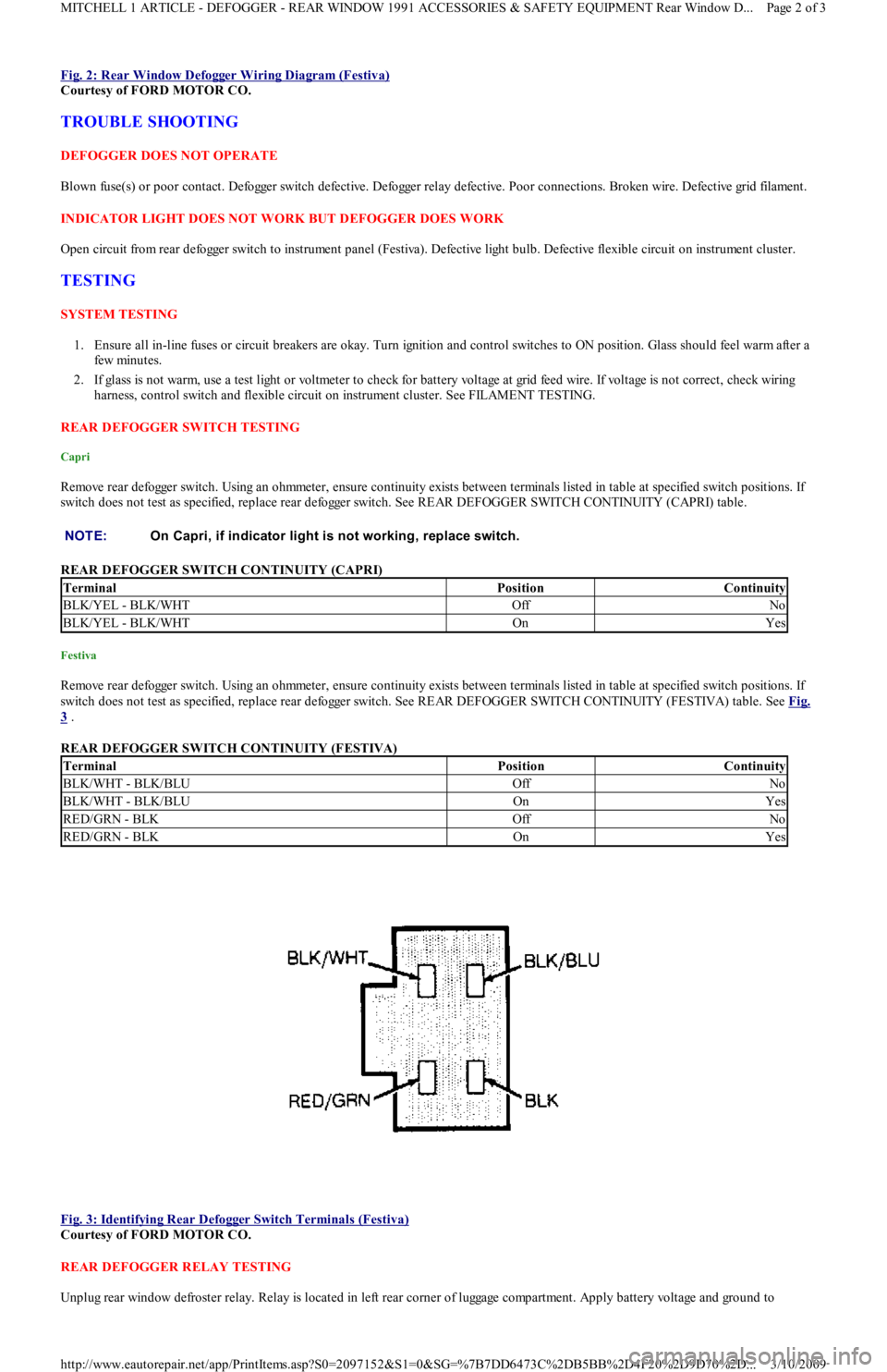
Fig. 2: Rear Window Defogger Wiring Diagram (Festiva)
Courtesy of FORD MOTOR CO.
TROUBLE SHOOTING
DEFOGGER DOES NOT OPERATE
Blown fuse(s) or poor contact. Defogger switch defective. Defogger relay defective. Poor connections. Broken wire. Defective grid filament.
INDICATOR LIGHT DOES NOT WORK BUT DEFOGGER DOES WORK
Open circuit from rear defogger switch to instrument panel (Festiva). Defective light bulb. Defective flexible circuit on instrument cluster.
TESTING
SYSTEM TESTING
1. Ensure all in-line fuses or circuit breakers are okay. Turn ignition and control switches to ON position. Glass should feel warm after a
few min u t es.
2. If glass is not warm, use a test light or voltmeter to check for battery voltage at grid feed wire. If voltage is not correct, check wiring
harness, control switch and flexible circuit on instrument cluster. See FILAMENT TESTING.
REAR DEFOGGER SWITCH TESTING
Capri
Remove rear defogger switch. Using an ohmmeter, ensure continuity exists between terminals listed in table at specified switch positions. If
switch does not test as specified, replace rear defogger switch. See REAR DEFOGGER SWITCH CONTINUITY (CAPRI) table.
REAR DEFOGGER SWITCH CONTINUITY (CAPRI)
Festiva
Remove rear defogger switch. Using an ohmmeter, ensure continuity exists between terminals listed in table at specified switch positions. If
switch does not test as specified, replace rear defogger switch. See REAR DEFOGGER SWITCH CONTINUITY (FESTIVA) table. See Fig.
3 .
REAR DEFOGGER SWITCH CONTINUITY (FESTIVA)
Fig. 3: Identifying Rear Defogger Switch Terminals (Festiva)
Courtesy of FORD MOTOR CO.
REAR DEFOGGER RELAY TESTING
Unplug rear window defroster relay. Relay is located in left rear corner of luggage compartment. Apply battery voltage and ground to NOTE:On Capri, if indicator light is not working, replace switch.
TerminalPositionContinuity
BLK/YEL - BLK/WHTOffNo
BLK/YEL - BLK/WHTOnYes
TerminalPositionContinuity
BLK/WHT - BLK/BLUOffNo
BLK/WHT - BLK/BLUOnYes
RED/GRN - BLKOffNo
RED/GRN - BLKOnYes
Page 2 of 3 MITCHELL 1 ARTICLE - DEFOGGER - REAR WINDOW 1991 ACCESSORIES & SAFETY EQUIPMENT Rear Window D
...
3/10/2009 http://www.eautorepair.net/app/PrintItems.asp?S0=2097152&S1=0&SG=%7B7DD6473C%2DB5BB%2D4F20%2D9D70%2D
...
Page 15 of 454
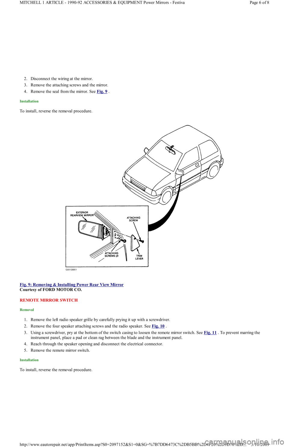
2. Disconnect the wiring at the mirror.
3. Remove the attaching screws and the mirror.
4. Remove the seal from the mirror. See Fig. 9
.
Installation
To install, reverse the removal procedure.
Fig. 9: Removing & Installing Power Rear View Mirror
Courtesy of FORD MOTOR CO.
REMOTE MIRROR SWITCH
Removal
1. Remove the left radio speaker grille by carefully prying it up with a screwdriver.
2. Remove the four speaker attaching screws and the radio speaker. See Fig. 10
.
3. Using a screwdriver, pry at the bottom of the switch casing to loosen the remote mirror switch. See Fig. 11
. To prevent marring the
instrument panel, place a pad or clean rag between the blade and the instrument panel.
4. Reach through the speaker opening and disconnect the electrical connector.
5. Remove the remote mirror switch.
Installation
To install, reverse the removal procedure.
Page 6 of 8 MITCHELL 1 ARTICLE - 1990-92 ACCESSORIES & EQUIPMENT Power Mirrors - Festiva
3/10/2009 http://www.eautorepair.net/app/PrintItems.asp?S0=2097152&S1=0&SG=%7B7DD6473C%2DB5BB%2D4F20%2D9D70%2D
...
Page 18 of 454
Back To Article
ST EERING COLUMN SWIT CHES
1991 ACCESSORIES & SAFET Y EQUIPMENT Ford Motor Co. Steering Colum n Switches
DESCRIPTION & OPERATION
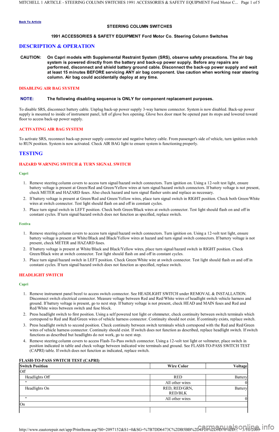
DISABLING AIR BAG SYSTEM
To disable SRS, disconnect battery cable. Unplug back-up power supply 3-way harness connector. System is now disabled. Back-up power
supply is mounted to inside of instrument panel, left of glove box opening. Glove box door must be opened past its stops and lowered toward
floor to access back-up power supply.
ACTIVATING AIR BAG SYSTEM
To activate SRS, reconnect back-up power supply connector and negative battery cable. From passenger's side of vehicle, turn ignition switch
to RUN position. System is now activated. Check AIR BAG light to ensure system is functioning properly.
TESTING
HAZARD WARNING SWITCH & TURN SIGNAL SWITCH
Capri
1. Remove steering column covers to access turn signal/hazard switch connectors. Turn ignition on. Using a 12-volt test light, ensure
battery voltage is present at Green/Red and Green/Yellow wires at turn signal/hazard switch connectors. If battery voltage is not present,
check METER and HAZARD fuses. Also check hazard and turn signal flasher units and replace as necessary.
2. If battery voltage is present at Green/Red and Green/Yellow wires, place turn signal switch in RIGHT position. Check both Green/White
wires at switch connector. Test light should flash on and off in constant cycles.
3. Place turn signal switch in LEFT position. Check both Green/Black wires at switch connector. Test light should flash on and off in
constant cycles. If turn signal/hazard switch does not function as specified, replace switch.
Festiva
1. Remove steering column covers to access turn signal/hazard switch connectors. Turn ignition on. Using a 12-volt test light, ensure
battery voltage is present at White/Black and Black/Yellow wires at hazard and turn signal switch connectors. If battery voltage is not
present, check METER and HAZARD fuses.
2. If battery voltage is present at White/Black and Black/Yellow wires, place turn signal/hazard switch in RIGHT position. Check
Green/Black wire at switch connector. Test light should flash on and off in constant cycles.
3. Place turn signal/hazard switch in LEFT position. Check Green/White wire at switch connector. Test light should flash on and off in
constant cycles. If turn signal/hazard switch does not function as specified, replace switch.
HEADLIGHT SWITCH
Capri
1. Remove instrument panel bezel to access switch connector. See HEADLIGHT SWITCH under REMOVAL & INSTALLATION.
Disconnect switch electrical connector. Measure voltage between Red and Red/White wires of headlight switch vehicle harness and
ground. If battery voltage is present, go to next step. If battery voltage is not present, check HEAD and MAIN fuses and Red and
Red/White wires between switch and fuse block.
2. Press headlight switch to first position. Using a self powered test light or ohmmeter, check continuity between switch terminals which
correspond to Red and Red/Green wires of vehicle harness connector. Continuity should not exist. If continuity exists, replace switch.
3. Press headlight switch to second position. Check continuity between switch terminals which correspond with the Red and Red/Green
wires of vehicle harness connector. Continuity should exist. If switch does not function as described, replace headlight switch. If swit ch
functions as described but headlights do not work, go to next step.
4. Remove steering column covers to access Flash-To-Pass switch connector. Using a 12-volt test light or voltmeter, place switch in
position indicated in table and check voltage between indicated wire terminals and ground. See FLASH-TO-PASS SWITCH TEST
(CAPRI) table. If switch does not function as indicated, replace switch.
FLASH-TO-PASS SWITCH TEST (CAPRI) CAUTION: On Capri m odels with Supplem ental Restraint System (SRS), observe safety precautions. T he air bag
system is powered directly from the battery and back-up power supply. Before any repairs are
perform ed, disconnect and shield battery ground cable. Disconnect the back-up power supply and wait
at least 15 m inutes BEFORE servicing ANY air bag com ponent. Use caution when working near steering
colum n. Air bag could accidentally deploy at any tim e.
NOTE:T he following disabling sequence is ONLY for com ponent replacem ent purposes.
Switch PositionWire ColorVoltage
Off
Headlights OffREDBattery
"All other wires0
Headlights OnRED, RED/GRN,
RED/BLKBattery
"All other wires0
On
Page 1 of 5 MITCHELL 1 ARTICLE - STEERING COLUMN SWITCHES 1991 ACCESSORIES & SAFETY EQUIPMENT Ford Motor C
...
3/10/2009 http://www.eautorepair.net/app/PrintItems.asp?S0=2097152&S1=0&SG=%7B7DD6473C%2DB5BB%2D4F20%2D9D70%2D
...
Page 21 of 454
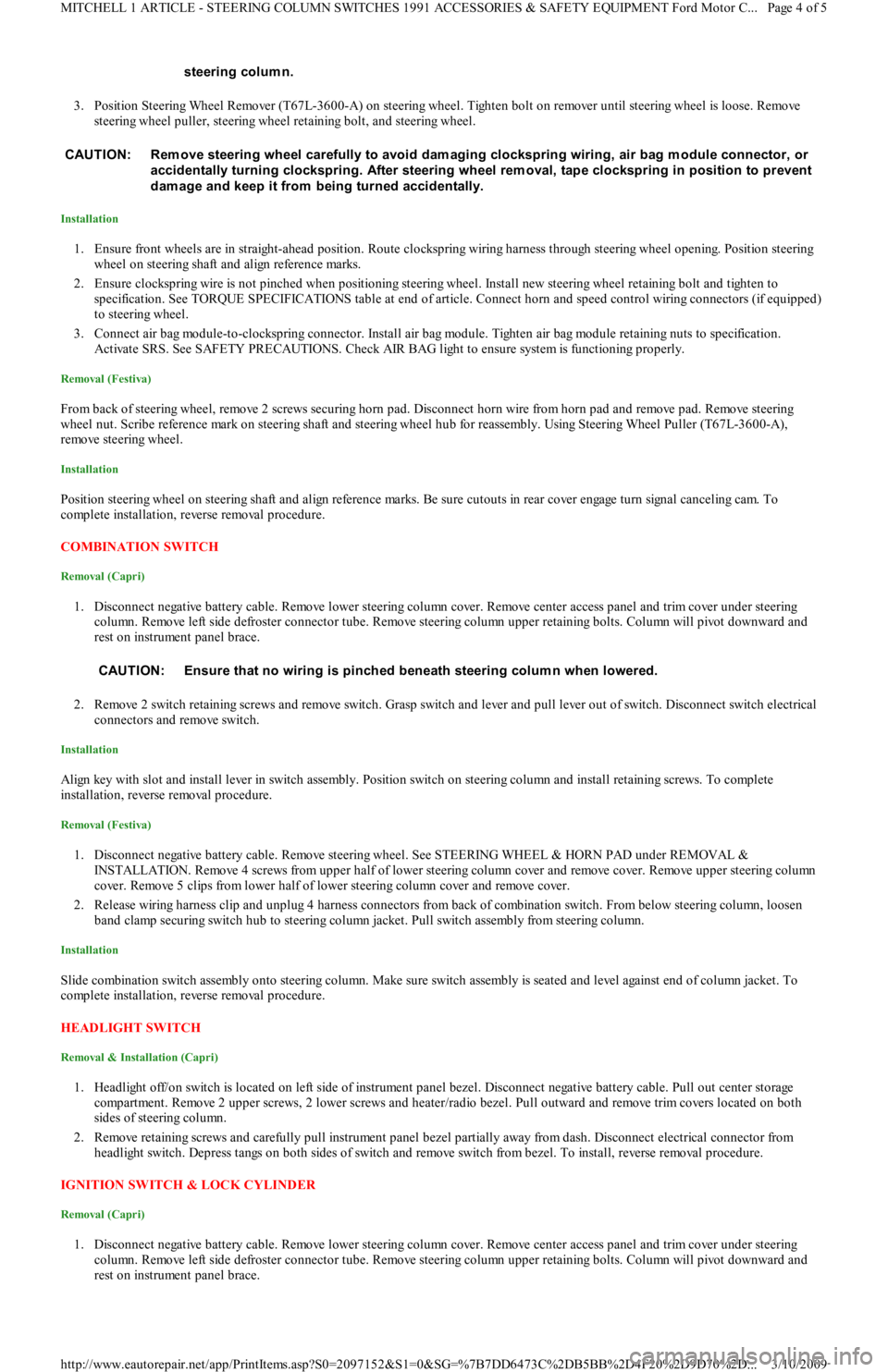
3. Position Steering Wheel Remover (T67L-3600-A) on steering wheel. Tighten bolt on remover until steering wheel is loose. Remove
steering wheel puller, steering wheel retaining bolt, and steering wheel.
Installation
1. Ensure front wheels are in straight-ahead position. Route clockspring wiring harness through steering wheel opening. Position steering
wheel on steering shaft and align reference marks.
2. Ensure clockspring wire is not pinched when positioning steering wheel. Install new steering wheel retaining bolt and tighten to
specification. See TORQUE SPECIFICATIONS table at end of article. Connect horn and speed control wiring connectors (if equipped)
to steering wheel.
3. Connect air bag module-to-clockspring connector. Install air bag module. Tighten air bag module retaining nuts to specification.
Activate SRS. See SAFETY PRECAUTIONS. Check AIR BAG light to ensure system is functioning properly.
Removal (Festiva)
From back of steering wheel, remove 2 screws securing horn pad. Disconnect horn wire from horn pad and remove pad. Remove steering
wheel nut. Scribe reference mark on steering shaft and steering wheel hub for reassembly. Using Steering Wheel Puller (T67L-3600-A),
remove steering wheel.
Installation
Position steering wheel on steering shaft and align reference marks. Be sure cutouts in rear cover engage turn signal canceling cam. To
complete installation, reverse removal procedure.
COMBINATION SW ITCH
Removal (Capri)
1. Disconnect negative battery cable. Remove lower steering column cover. Remove center access panel and trim cover under steering
column. Remove left side defroster connector tube. Remove steering column upper retaining bolts. Column will pivot downward and
rest on instrument panel brace.
2. Remove 2 switch retaining screws and remove switch. Grasp switch and lever and pull lever out of switch. Disconnect switch electrical
connectors and remove switch.
Installation
Align key with slot and install lever in switch assembly. Position switch on steering column and install retaining screws. To complete
installation, reverse removal procedure.
Removal (Festiva)
1. Disconnect negative battery cable. Remove steering wheel. See STEERING WHEEL & HORN PAD under REMOVAL &
INSTALLATION. Remove 4 screws from upper half of lower steering column cover and remove cover. Remove upper steering column
cover. Remove 5 clips from lower half of lower steering column cover and remove cover.
2. Release wiring harness clip and unplug 4 harness connectors from back of combination switch. From below steering column, loosen
band clamp securing switch hub to steering column jacket. Pull switch assembly from steering column.
Installation
Slide combination switch assembly onto steering column. Make sure switch assembly is seated and level against end of column jacket. To
complete installation, reverse removal procedure.
HEADLIGHT SWITCH
Removal & Installation (Capri)
1. Headlight off/on switch is located on left side of instrument panel bezel. Disconnect negative battery cable. Pull out center storage
compartment. Remove 2 upper screws, 2 lower screws and heater/radio bezel. Pull outward and remove trim covers located on both
sides of steering column.
2. Remove retaining screws and carefully pull instrument panel bezel partially away from dash. Disconnect electrical connector from
headlight switch. Depress tangs on both sides of switch and remove switch from bezel. To install, reverse removal procedure.
IGNITION SWITCH & LOCK CYLINDER
Removal (Capri)
1. Disconnect negative battery cable. Remove lower steering column cover. Remove center access panel and trim cover under steering
column. Remove left side defroster connector tube. Remove steering column upper retaining bolts. Column will pivot downward and
rest on instrument panel brace. steering colum n.
CAUT ION: Rem ove steering wheel carefully to avoid dam aging clockspring wiring, air bag m odule connector, or
accidentally turning clockspring. After steering wheel rem oval, tape clockspring in position to prevent
dam age and keep it from being turned accidentally.
CAUTION: Ensure that no wiring is pinched beneath steering colum n when lowered.
Page 4 of 5 MITCHELL 1 ARTICLE - STEERING COLUMN SWITCHES 1991 ACCESSORIES & SAFETY EQUIPMENT Ford Motor C
...
3/10/2009 http://www.eautorepair.net/app/PrintItems.asp?S0=2097152&S1=0&SG=%7B7DD6473C%2DB5BB%2D4F20%2D9D70%2D
...
Page 23 of 454
Back To Article
WIPER/WASHER SYST EM
1991 ACCESSORIES & SAFET Y EQUIPMENT Ford Motor Co. Wiper/Washer System s
DESCRIPTION & OPERATION
Capri and Festiva vehicles are equipped with a 2-speed wiper motor with an optional intermittent system. The Festiva rear wiper uses a single
speed wiper motor. Washer systems for both front and rear washers use pumps mounted near fluid reservoirs.
ADJUSTMENTS
W IPER ARM ADJUSTMENT
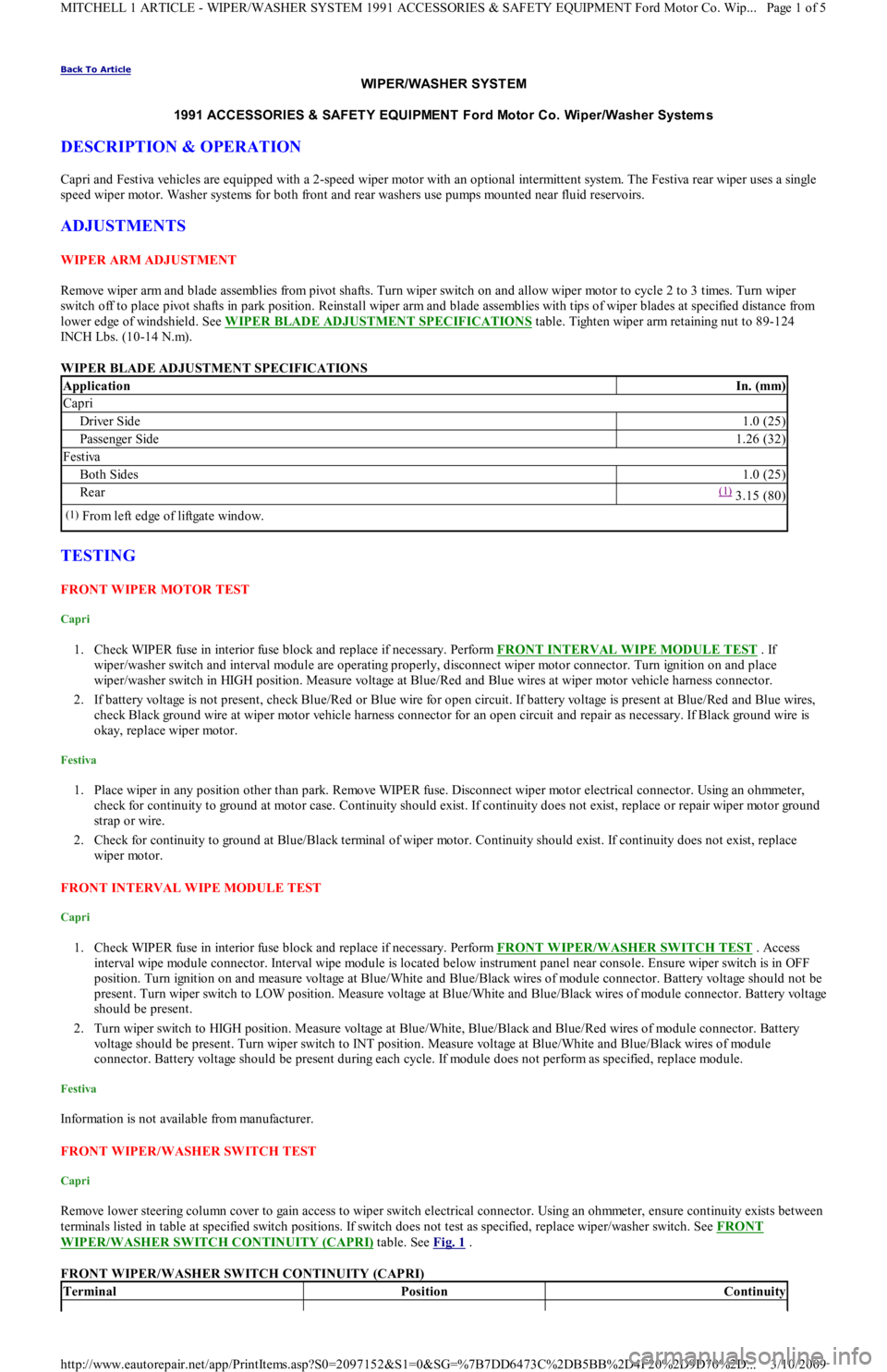
Remove wiper arm and blade assemblies from pivot shafts. Turn wiper switch on and allow wiper motor to cycle 2 to 3 times. Turn wiper
switch off to place pivot shafts in park position. Reinstall wiper arm and blade assemblies with tips of wiper blades at specified distance from
lower edge of windshield. See WIPER BLADE ADJUSTMENT SPECIFICATIONS
table. Tighten wiper arm retaining nut to 89-124
INCH Lbs. (10-14 N.m).
WIPER BLADE ADJUSTMENT SPECIFICATIONS
TESTING
FRONT WIPER MOTOR TEST
Capri
1. Check WIPER fuse in interior fuse block and replace if necessary. Perform FRONT INTERVAL WIPE MODULE TEST . If
wiper/washer switch and interval module are operating properly, disconnect wiper motor connector. Turn ignition on and place
wiper/washer switch in HIGH position. Measure voltage at Blue/Red and Blue wires at wiper motor vehicle harness connector.
2. If battery voltage is not present, check Blue/Red or Blue wire for open circuit. If battery voltage is present at Blue/Red and Blue wires,
check Black ground wire at wiper motor vehicle harness connector for an open circuit and repair as necessary. If Black ground wire is
okay, replace wiper motor.
Festiva
1. Place wiper in any position other than park. Remove WIPER fuse. Disconnect wiper motor electrical connector. Using an ohmmeter,
check for continuity to ground at motor case. Continuity should exist. If continuity does not exist, replace or repair wiper motor ground
strap or wire.
2. Check for continuity to ground at Blue/Black terminal of wiper motor. Continuity should exist. If continuity does not exist, replace
wiper motor.
FRONT INTERVAL WIPE MODULE TEST
Capri
1. Check WIPER fuse in interior fuse block and replace if necessary. Perform FRONT WIPER/WASHER SWITCH TEST . Access
interval wipe module connector. Interval wipe module is located below instrument panel near console. Ensure wiper switch is in OFF
position. Turn ignition on and measure voltage at Blue/White and Blue/Black wires of module connector. Battery voltage should not be
present. Turn wiper switch to LOW position. Measure voltage at Blue/White and Blue/Black wires of module connector. Battery voltage
should be present.
2. Turn wiper switch to HIGH position. Measure voltage at Blue/White, Blue/Black and Blue/Red wires of module connector. Battery
voltage should be present. Turn wiper switch to INT position. Measure voltage at Blue/White and Blue/Black wires of module
connector. Battery voltage should be present during each cycle. If module does not perform as specified, replace module.
Festiva
Information is not available from manufacturer.
FRONT WIPER/WASHER SWITCH TEST
Capri
Remove lower steering column cover to gain access to wiper switch electrical connector. Using an ohmmeter, ensure continuity exists between
terminals listed in table at specified switch positions. If switch does not test as specified, replace wiper/washer switch. See FRONT
WIPER/WASHER SWITCH CONTINUITY (CAPRI) table. See Fig. 1 .
FRONT WIPER/WASHER SWITCH CONTINUITY (CAPRI)
ApplicationIn. (mm)
Capri
Driver Side1.0 (25)
Passenger Side1.26 (32)
Festiva
Both Sides1.0 (25)
Rear(1) 3.15 (80)
(1)From left edge of liftgate window.
TerminalPositionContinuity
Page 1 of 5 MITCHELL 1 ARTICLE - WIPER/WASHER SYSTEM 1991 ACCESSORIES & SAFETY EQUIPMENT Ford Motor Co. Wip
...
3/10/2009 http://www.eautorepair.net/app/PrintItems.asp?S0=2097152&S1=0&SG=%7B7DD6473C%2DB5BB%2D4F20%2D9D70%2D
...
Page 27 of 454
Disconnect fluid lines and remove reservoir. To install, reverse removal procedure.
Removal & Installation (Festiva)
1. Disconnect negative battery cable. Remove washer reservoir filler neck attaching bolt. Remove coolant expansion reservoir. Disconnect
washer pump electrical connector. Remove left front splash shield.
2. Disconnect washer pump fluid lines and detach lines from reservoir clips. Remove reservoir attaching nuts and bolt. Detach washer
reservoir from filler neck and remove reservoir. To install, reverse removal procedure.
REAR WIPER MOTOR
Removal & Installation (Festiva)
Remove rear wiper arm and blade assembly. Remove boot from outer bushing attaching nut. Remove outer bushing attaching nut and remove
outer bushing. Remove liftgate trim panel. Disconnect wiper motor electrical connector. Remove 4 wiper motor mounting bolts and remove
motor. To install, reverse removal procedure.
REAR WIPER/WASHER SWITCH
Removal & Installation (Festiva)
Disconnect negative battery cable. Remove steering column covers. Remove screws securing instrument panel bezel to instrument panel. Pull
instrument bezel away from instrument panel. Disconnect electrical connectors from switches in bezel. Compress wiper/washer switch lock
tabs and remove switch from bezel. To install, reverse removal procedure.
REAR WASHER MOTOR & RESERVOIR
Removal & Installation (Festiva)
Open liftgate and detach reservoir cap. Remove rear quarter trim panel. Remove reservoir mounting bolts. Disconnect electrical connector
from washer pump. Disconnect fluid lines. Remove reservoir. To install, reverse removal procedure.
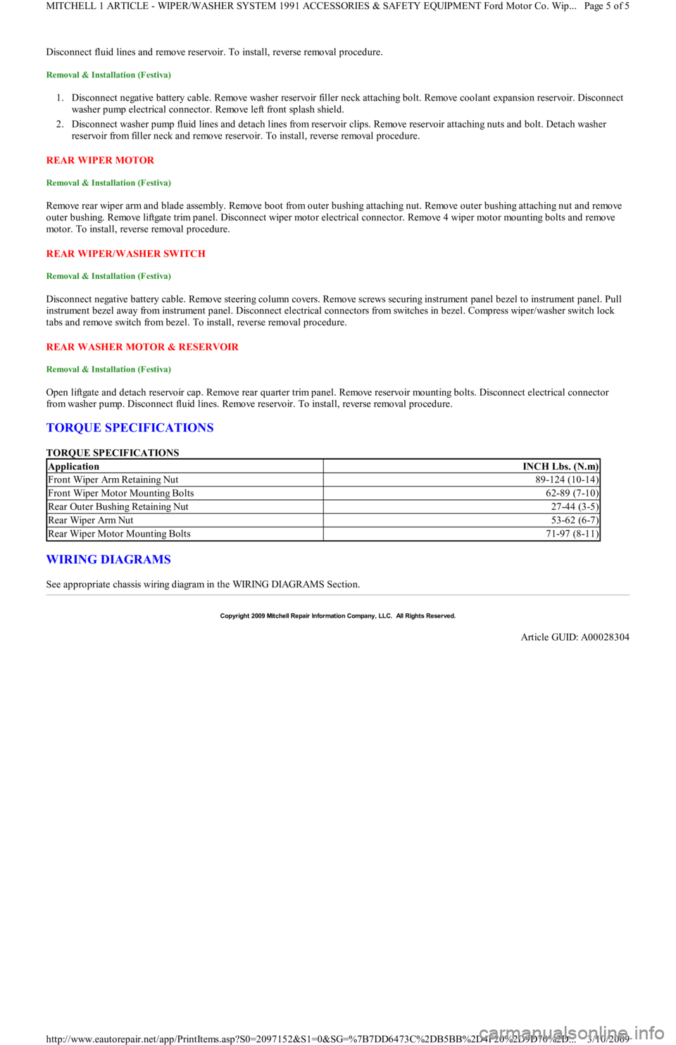
TORQUE SPECIFICATIONS
TORQUE SPECIFICATIONS
WIRING DIAGRAMS
See appropriate chassis wiring diagram in the WIRING DIAGRAMS Section.
ApplicationINCH Lbs. (N.m)
Front Wiper Arm Retaining Nut89-124 (10-14)
Front Wiper Motor Mounting Bolts62-89 (7-10)
Rear Outer Bushing Retaining Nut27-44 (3-5)
Rear Wiper Arm Nut53-62 (6-7)
Rear Wiper Motor Mounting Bolts71-97 (8-11)
Copyr ight 2009 Mitchell Repair Information Company, LLC. All Rights Reserved.
Article GUID: A00028304
Page 5 of 5 MITCHELL 1 ARTICLE - WIPER/WASHER SYSTEM 1991 ACCESSORIES & SAFETY EQUIPMENT Ford Motor Co. Wip
...
3/10/2009 http://www.eautorepair.net/app/PrintItems.asp?S0=2097152&S1=0&SG=%7B7DD6473C%2DB5BB%2D4F20%2D9D70%2D
...