1991 FORD FESTIVA open
[x] Cancel search: openPage 28 of 454
Back To Article
BRAKE SYST EM
1991-92 BRAKES Disc & Drum
DESCRIPTION & OPERATION
On Capri, vehicle braking is provided by front and rear disc brakes. Front and rear brakes are a full-floating, single piston design. The rear
caliper houses a self-adjusting parking brake.
On Festiva, vehicle braking is provided by front disc brakes and rear drum brakes. Rear brakes are a standard non-servo, self-en e r giz in g d e sign .
Front brakes are a full-floating, single piston design with caliper attached to steering knuckle.
BLEEDING BRAKE SYSTEM
BLEEDING PROCEDURES
Manual Bleeding
1. Exhaust vacuum from power brake unit by depressing brake pedal several times. Fill master cylinder with clean brake fluid. Install clear
vinyl bleeder hose onto first bleeder valve to be serviced. See BRAKE LINE BLEEDING SEQUENCE table. Place other end of hose in
clean transparent container.
2. Partially fill container with clean brake fluid. Open the bleeder valve 3/4 turn. Slowly depress brake pedal through its full travel. Close
bleeder valve and release pedal. Pump pedal several times to push air toward wheel cylinders. Repeat procedure until flow of brake
fluid is clear and shows no signs of air bubbles. Proceed to next bleeder valve in sequence and repeat procedure.
BRAKE LINE BLEEDING SEQUENCE
Pressure Bleeding
1. Exhaust vacuum from power brake unit by depressing brake pedal several times. Fill master cylinder with clean brake fluid. With
pressure bleeder at least 1/2 full, connect pressure bleeder to master cylinder using appropriate adaptor.
2. Install clear vinyl bleeder hose onto first bleeder valve to be serviced. See BRAKE LINE BLEEDING SEQUENCE table. Place other
end of hose in clean transparent container. Partially fill container with clean brake fluid. Open bleeder valve 1-2 turns. Allow fluid to
run until flow of fluid is clear and shows no signs of air bubbles. Proceed to next bleeder valve in sequence and repeat procedure.
Remove pressure bleeder and fill master cylinder with clean brake fluid.
ADJUSTMENTS
BRAKE PEDAL HEIGHT (FESTIVA)
1. Block wheels to prevent vehicle from rolling. Start engine and place transmission in Neutral. Fully release parking brake. Move carpet
and insulation away from firewall and brake pedal. Measure distance horizontally between upper center of brake pedal pad and firewall.
Distance should be 8.03-8.23" (204-209 mm).
2. If pedal height is incorrect, inspect pedal assembly for missing, worn or damaged bushings or for loose attaching bolts. Ensure firewall is
not distorted and pedal is not bent. If pedal height is still not within specifications, check brake pedal, booster or master cylinder for
correct and/or correctly installed parts
BRAKE PEDAL FREE PLAY (FESTIVA)
Pump brake pedal several to bleed vacuum from power brake booster. Gently depress brake pedal by hand and measure and measure play
before resistance is felt. Free play should be .16-.28" (4-7 mm). If free play is not within specifications, adjust brake pedal push rod.
BRAKE PEDAL FLOOR CLEARANCE
Capri
1. Move carpet and insulation away from floor board and brake pedal. With engine running and using Brake Pedal Effort Gauge (021-
00001), apply 132 lbs. (59.9 kg) of force to brake pedal. Measure distance from upper surface of brake pedal pad to floor board. If
distance is less than 3.27" (83 mm), inspect pedal assembly for missing, worn or damaged bushings or for loose attaching bolts.
2. Verify that floor board is not distorted and pedal is not bent. If pedal height is still not within specifications, check brake pedal, booster
or master cylinder for correct and/or correctly installed parts. Check for air in hydraulic system.
Festiva
Move carpet and insulation away from floor board and brake pedal. Using Brake Pedal Effort Gauge (021-00001) or equivalent, apply 132
lbs. (59.9 kg) of force to brake pedal. Measure distance from upper surface of brake pedal pad to floor board. If distance is less than 2.68" (68
mm), check for air in hydraulic system, faulty automatic adjusters or excessive shoe clearance.
POWER BRAKE UNIT PUSH ROD
Capri
ApplicationSequence
CapriRR, LF, LR & RF
FestivaRR, LR, RF & LF
NOTE:Check fluid level in m aster cylinder frequently during the bleeding sequence.
Page 1 of 12 MITCHELL 1 ARTICLE - BRAKE SYSTEM 1991-92 BRAKES Disc & Drum
3/10/2009 http://www.eautorepair.net/app/PrintItems.asp?S0=2097152&S1=0&SG=%7B7DD6473C%2DB5BB%2D4F20%2D9D70%2D
...
Page 40 of 454
Back To Article
AXLE SHAFT S - FRONT
1988-93 Drive Axles - FWD Axle Shafts
DESCRIPTION & OPERATION
Axle shafts transfer power from transaxle to driving wheels. All axle shafts consist of a shaft with a flexible Constant Velocity (CV) joint at
each end. Inner CV joint is coupled to transaxle by splines. Outer CV joint is splined to hub assembly and secured by axle shaft nut.
Three different types of axle shaft CV joints are used: Double Offset Joint (DOJ) or Rzeppa type, Birfield Joint (BJ) and the Tripot Joint (TJ).
CV joint boots protect CV joints by maintaining proper lubrication and preventing contaminants from entering joint. Boots must be replaced
when signs of leakage or cracks are present. Inner CV joint may be disassembled and serviced. Outer CV joint boot may be replaced, but outer
Birfield CV joint must NOT be disassembled. It must be replaced as an assembly, if faulty.
To prevent torsional vibration and torque steer on turbocharged Capri vehicles, an intermediate shaft and conventional axle shaft are used on
the right side. Both shafts are of similar length and are supported by a bearing, which is attached to engine.
CV JOINT IDENTIFICATION
TROUBLE SHOOTING
REMOVAL, DISASSEMBLY, REASSEMBLY & INSTALLATION
FWD AXLE SHAFTS
Removal
1. Raise and support vehicle. Remove lower underbody splash shields. Drain transaxle fluid. Remove front wheels and loosen axle shaft
lock nut. On Capri, remove stabilizer bar-to-control arm attaching nuts, bolt, washers and bushings. On Festiva, remove stabilizer bar
attaching nuts and bracket. On all models, remove joint clamp bolt from lower control arm. Pry downward and separate steering knuckle
from ball joint, taking care not to damage ball joint dust boot.
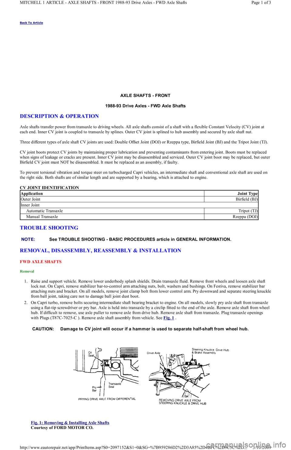
2. On Capri turbo, remove bolts securing intermediate shaft bearing bracket to engine. On all models, slowly pry axle shaft from transaxle
using a flat-tip screwdriver or pry bar. Axle is held into transaxle by a circlip fitted to the end of the axle. Remove axle shaft from wheel
hub. If difficult to remove, use axle puller to remove axle from drive hub. Remove axle shaft from transaxle. Plug transaxle openings
with Plugs (T87C-7025-C ). Remove axle shaft assembly from vehicle. See Fig. 1
.
Fig. 1: Removing & Installing Axle Shafts
Courtesy of FORD MOTOR CO.
ApplicationJoint Type
Outer JointBirfield (BJ)
In n er Jo in t
Automatic TransaxleTripot (TJ)
Manual TransaxleRzeppa (DOJ)
NOTE:See TROUBLE SHOOTING - BASIC PROCEDURES article in GENERAL INFORMATION.
CAUTION: Dam age to CV joint will occur if a ham mer is used to separate half-shaft from wheel hub.
Page 1 of 3 MITCHELL 1 ARTICLE - AXLE SHAFTS - FRONT 1988-93 Drive Axles - FWD Axle Shafts
3/10/2009 http://www.eautorepair.net/app/PrintItems.asp?S0=2097152&S1=0&SG=%7B959286D2%2D3A85%2D4BFC%2D9C5C%2D
...
Page 44 of 454
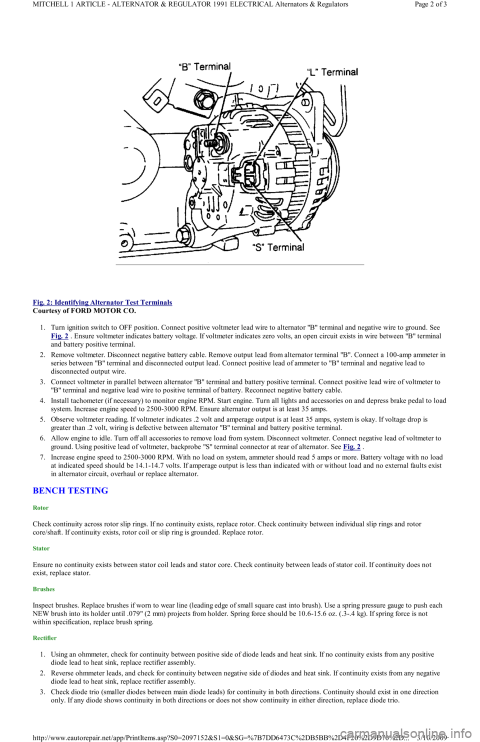
Fig. 2: Identifying Alternator Test Terminals
Courtesy of FORD MOTOR CO.
1. Turn ignition switch to OFF position. Connect positive voltmeter lead wire to alternator "B" terminal and negative wire to ground. See
Fig. 2
. Ensure voltmeter indicates battery voltage. If voltmeter indicates zero volts, an open circuit exists in wire between "B" terminal
and battery positive terminal.
2. Remove voltmeter. Disconnect negative battery cable. Remove output lead from alternator terminal "B". Connect a 100-amp ammeter in
series between "B" terminal and disconnected output lead. Connect positive lead of ammeter to "B" terminal and negative lead to
disconnected output wire.
3. Connect voltmeter in parallel between alternator "B" terminal and battery positive terminal. Connect positive lead wire of voltmeter to
"B" terminal and negative lead wire to positive terminal of battery. Reconnect negative battery cable.
4. Install tachometer (if necessary) to monitor engine RPM. Start engine. Turn all lights and accessories on and depress brake pedal to load
system. Increase engine speed to 2500-3000 RPM. Ensure alternator output is at least 35 amps.
5. Observe voltmeter reading. If voltmeter indicates .2 volt and amperage output is at least 35 amps, system is okay. If voltage drop is
greater than .2 volt, wiring is defective between alternator "B" terminal and battery positive terminal.
6. Allow engine to idle. Turn off all accessories to remove load from system. Disconnect voltmeter. Connect negative lead of voltmeter to
ground. Using positive lead of voltmeter, backprobe "S" terminal connector at rear of alternator. See Fig. 2
.
7. Increase engine speed to 2500-3000 RPM. With no load on system, ammeter should read 5 amps or more. Battery voltage with no load
at indicated speed should be 14.1-14.7 volts. If amperage output is less than indicated with or without load and no external faults exist
in alternator circuit, overhaul or replace alternator.
BENCH TESTING
Rotor
Check continuity across rotor slip rings. If no continuity exists, replace rotor. Check continuity between individual slip rings and rotor
core/shaft. If continuity exists, rotor coil or slip ring is grounded. Replace rotor.
Stator
Ensure no continuity exists between stator coil leads and stator core. Check continuity between leads of stator coil. If continuity does not
exist, replace stator.
Brushes
Inspect brushes. Replace brushes if worn to wear line (leading edge of small square cast into brush). Use a spring pressure gauge to push each
NEW brush into its holder until .079" (2 mm) projects from holder. Spring force should be 10.6-15.6 oz. (.3-.4 kg). If spring force is not
within specification, replace brush spring.
Rectifier
1. Using an ohmmeter, check for continuity between positive side of diode leads and heat sink. If no continuity exists from any positive
diode lead to heat sink, replace rectifier assembly.
2. Reverse ohmmeter leads, and check for continuity between negative side of diodes and heat sink. If continuity exists from any n e ga t ive
diode lead to heat sink, replace rectifier assembly.
3. Check diode trio (smaller diodes between main diode leads) for continuity in both directions. Continuity should exist in one direction
only. If any diode shows continuity in both directions or does not show continuity in either direction, replace diode trio.
Page 2 of 3 MITCHELL 1 ARTICLE - ALTERNATOR & REGULATOR 1991 ELECTRICAL Alternators & Regulators
3/10/2009 http://www.eautorepair.net/app/PrintItems.asp?S0=2097152&S1=0&SG=%7B7DD6473C%2DB5BB%2D4F20%2D9D70%2D
...
Page 46 of 454

Back To Article
ELECT RICAL COMPONENT LOCAT OR
1991-92 ELECT RICAL COMPONENT LOCAT ION Ford Motor Co. Electrical Com ponents
BUZZERS, RELAYS & TIMERS
BUZZERS, RELAYS & TIMERS LOCATION
CIRCUIT PROTECTION DEVICES
CIRCUIT PROTECTION DEVICES LOCATION
CONTROL UNITS
CONTROL UNITS LOCATION
SENDING UNITS & SENSORS
SENDING UNITS & SENSORS LOCATION
MOTORS
MOTORS LOCATION
ComponentLocation
A/C Clutch Relay (1991)On right front of engine bay, near power
steering pump.
A/C RelayOn left front corner of engine bay, left of
cooling fan. See Fig. 1
& Fig. 2
A/C Wide Open Throttle (WAC) RelayOn left front corner of engine bay, left of
cooling fan. See Fig. 1
& Fig. 2 .
Cooling Fan RelayOn left front fender panel, near
headlight. See Fig. 1
& Fig. 2 .
Condenser Fan RelayOn left front of engine bay, left of
cooling fan. See Fig. 1
& Fig. 2 .
Daytime Running Light (DRL) Relay (Canada) (1992)On left front corner of engine bay, near
headlight. See Fig. 1
.
Fuel Pump RelayBehind left side of dash, near ECA.
Headlight RelayBehind left headlight. See Fig. 1 .
Horn RelayUnder left side of dash. See Fig. 3 .
Main RelayIn left front corner of engine bay, near
battery.
P a r kin g Ligh t R e l a yOn right front corner of engine bay. See
Fig. 1
.
Turn Signal/Flasher RelayUnder left side of dash, behind ECA.
See Fig. 3
.
ComponentLocation
A/C In-Line FuseOn left side of heater case.
Condenser Fan In-Line FuseOn right side of steering column.
Fuse PanelBehind access panel, to left of steering column.
Fusible LinksOn left front strut tower. See Fig. 1 .
ComponentLocation
Electronic Control Assembly (ECA)Behind left side of dash, left of steering column.
Passive Restraint ModuleUnder driver's seat.
ComponentLocation
Airflow MeterOn right front corner of engine bay. See Fig. 1 .
Coolant Temperature Sending UnitBelow thermostat housing.
Crankshaft Position SensorInside distributor. See Fig. 1 .
EGR Temperature Sensor (1991)In exhaust manifold, near EGR valve.
Engine Coolant Temperature (ECT) SensorOn top of engine, near injector No. 1.
Fuel Gauge Sending Unit (1992)In fu el t an k.
Throttle Position Sensor (TPS)On left side of throttle body. See Fig. 1 .
ComponentLocation
Blower MotorUnder center of dash, behind
radio.
Windshield Washer Motors:
Front (1991)On right front fender panel,
bottom of washer reservoir.
Front (1992)On left front corner of engine
bay, in front of battery.
RearOn body panel, behind right
rear quarter panel.
Windshield Wiper Motor
Page 1 of 3 MITCHELL 1 ARTICLE - ELECTRICAL COMPONENT LOCATOR 1991-92 ELECTRICAL COMPONENT LOCATION For...
3/10/2009 http://www.eautorepair.net/app/PrintItems.asp?S0=2097152&S1=0&SG=%7B959286D2%2D3A85%2D4BFC%2D9C5C%2D
...
Page 47 of 454
SOLENOIDS & SOLENOID VALVES
SOLENOIDS & SOLENOID VALVES LOCATION
SWITCHES
SWITCHES LOCATION
MISCELLANEOUS
MISCELLANEOUS LOCATION
COMPONENT LOCATION GRAPHICS
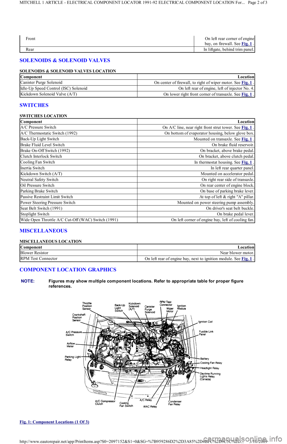
Fig. 1: Component Locations (1 Of 3)
FrontOn left rear corner of engine
bay, on firewall. See Fig. 1
.
RearIn liftgate, behind trim panel.
ComponentLocation
Canister Purge SolenoidOn center of firewall, to right of wiper motor. See Fig. 1 .
Idle-Up Speed Control (ISC) SolenoidOn left rear of engine, left of injector No. 4.
Kickdown Solenoid Valve (A/T)On lower right front corner of transaxle. See Fig. 1 .
ComponentLocation
A/C Pressure SwitchOn A/C line, near right front strut tower. See Fig. 1 .
A/C Thermostatic Switch (1992)On bottom of evaporator housing, below glove box.
Back-Up Light SwitchMounted on transaxle. See Fig. 1 .
Brake Fluid Level SwitchOn brake fluid reservoir.
Brake On-Off Switch (1992)On bracket, above brake pedal.
Clutch Interlock SwitchOn bracket, above clutch pedal.
Cooling Fan SwitchIn thermostat housing. See Fig. 1 .
Inertia SwitchIn left rear quarter panel.
Kickdown Switch (A/T)Mounted on accelerator pedal.
Neutral Safety SwitchOn right rear side of transaxle.
Oil Pressure SwitchOn rear center of engine block.
Parking Brake SwitchOn base of parking brake lever.
Passive Restraint Limit SwitchAt top of left & right "A" pillar.
Power Steering Pressure SwitchMounted on power steering pump assembly.
Seat Belt Switch (1991)On driver's seat belt buckle.
Stoplight SwitchOn brake pedal lever.
Wide Open Throttle A/C Cut-Off (WAC) Switch (1991)On left corner of engine bay, left of cooling fan.
ComponentLocation
Blower ResistorNear blower motor.
RPM Test ConnectorOn left rear of engine bay, next to ignition module. See Fig. 1 .
NOTE:Figures m ay show m ultiple com ponent locations. Refer to appropriate table for proper figure
references.
Page 2 of 3 MITCHELL 1 ARTICLE - ELECTRICAL COMPONENT LOCATOR 1991-92 ELECTRICAL COMPONENT LOCATION For...
3/10/2009 http://www.eautorepair.net/app/PrintItems.asp?S0=2097152&S1=0&SG=%7B959286D2%2D3A85%2D4BFC%2D9C5C%2D
...
Page 56 of 454
SOLENOID TEST
Disconnect wiring and cables from solenoid. Using an ohmmeter, check for continuity between terminal "M" and body of starter solenoid. See
Fig. 1
. Continuity should exist. If continuity does not exist, replace solenoid.
ARMATURE TEST
1. Place armature in growler. Turn on growler and hold a piece of hacksaw blade over armature. Slowly rotate armature. If hacksaw blade
is attracted to core or if it vibrates, replace armature.
2. Remove armature from growler. Using an ohmmeter, check continuity between commutator and core. If continuity exists, replace
armature. Check continuity between commutator and shaft. If continuity exists, replace armature.
3. Check continuity between each commutator segment. If an open exists between any 2 segments, replace armature.
COMMUTATOR TEST
1. Clean surface of commutator and polish with No. 400 grit sandpaper (if required). If surface is scored, out of round or pitted, turn
commutator on a lathe.
2. Maximum commutator runout and minimum diameter of commutator must not exceed specification after turning. See STARTER
MOTOR SPECIFICATIONS table.
3. Commutator mica undercut depth should be .02-.03" (.5-.8 mm). If undercut depth is not within specification, undercut with a hacksaw
blade to standard depth.
BRUSH & SPRING TEST
1. Connect ohmmeter between positive brush holder and negative brush holder. If ohmmeter indicates continuity, brush holder assemb l y is
shorted and must be replaced.
2. Check brush length. See STARTER MOTOR SPECIFICATIONS
table. If brush length is less than specification, replace brushes.
3. Check spring tension. Spring tension should be 2.0-4.3 Lbs. (8.8-19.1 N.m). Ensure brushes move freely in holders.
FIELD COIL TEST
1. Connect ohmmeter between field lead and soldered portion of brush lead. If continuity does not exist, repair or replace field coil.
2. Check field coil for shorts to ground by connecting ohmmeter between field lead and starter housing. If continuity exists, repair or
replace field coil.
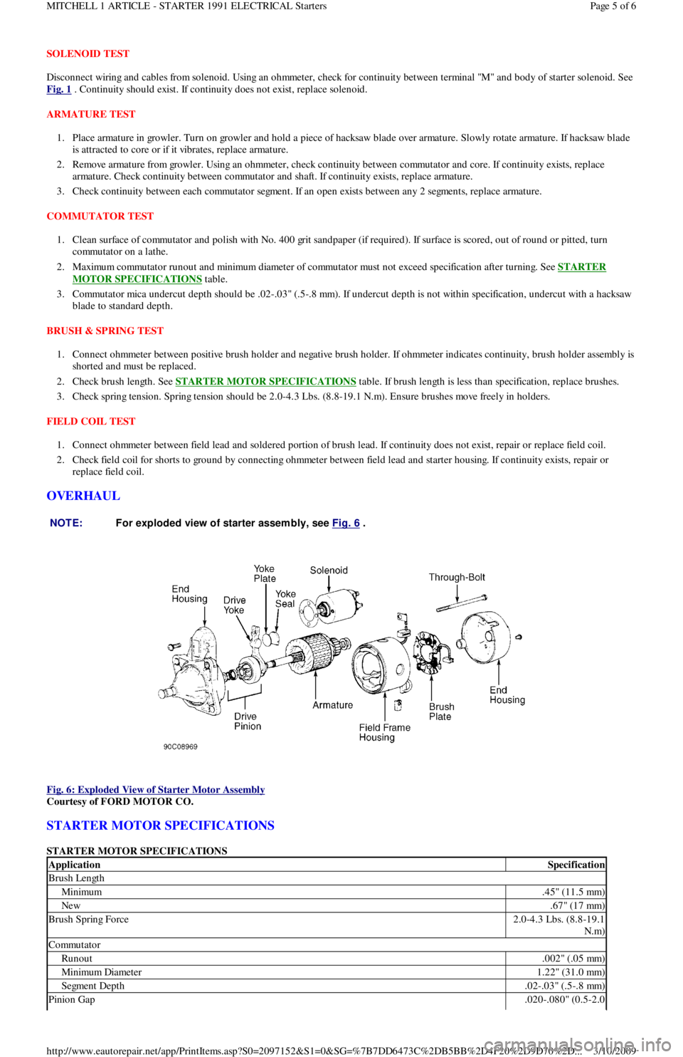
OVERHAUL
Fig. 6: Exploded View of Starter Motor Assembly
Courtesy of FORD MOTOR CO.
STARTER MOTOR SPECIFICATIONS
STARTER MOTOR SPECIFICATIONS NOTE:For exploded view of starter assem bly, see Fig. 6
.
ApplicationSpecification
Brush Length
Minimum.45" (11.5 mm)
New.67" (17 mm)
Brush Spring Force2.0-4.3 Lbs. (8.8-19.1
N.m)
Commutator
Runout.002" (.05 mm)
Min imu m Diamet er1.22" (31.0 mm)
Segment Depth.02-.03" (.5-.8 mm)
Pinion Gap.020-.080" (0.5-2.0
Page 5 of 6 MITCHELL 1 ARTICLE - STARTER 1991 ELECTRICAL Starters
3/10/2009 http://www.eautorepair.net/app/PrintItems.asp?S0=2097152&S1=0&SG=%7B7DD6473C%2DB5BB%2D4F20%2D9D70%2D
...
Page 86 of 454

Back To Article
ENGINE COOLING FAN
1990-92 ENGINE COOLING Ford Motor Co. Engine Cooling Fans
DESCRIPTION
Power for cooling fan is provided by the 20-amp COOLING fuse (Capri) or C-FAN fuse (Festiva). Cooling fan is activated when ground is
supplied for fan motor. On Festiva, ground can be supplied by fuel system ECA (located under the left side of dash), A/C cooling fan relay (if
equipped) or cooling fan relay. See Fig. 1
. On all models, when cooling fan is energized, relay contacts are open; when cooling fan is NOT
energized, relay contacts are closed, providing ground through closed contacts to activate cooling fan. See Fig. 2
.
Cooling fan relay is energized when coolant temperature switch is closed. This occurs when coolant temperature is less than 212°F (1 00 °C)
for Capri or 207°F (97°C) for Festiva. At temperatures greater than 212°F (100°C) for Capri or 207°F (97°C) for Festiva, coolant temperature
switch opens and cooling fan relay is de-energized, closing relay contacts and energizing cooling fan.
When ECA senses A/C request, it energizes A/C cooling fan relay by providing a ground for relay windings on ECA pin 1Q. Power for the
A/C cooling fan relay is provided by the HEATER fuse. On Capri, when A/C cooling fan relay is energized, it opens the power circuit for the
cooling fan relay. On Festiva, when A/C cooling fan relay is energized, it provides an alternate path to ground for cooling fan mo t o r. E CA al so
provides an alternate path to ground (at ECA pin 1R) for cooling fan motor based on input from coolant temperature sensor to ECA pin 2Q.
Fig. 1: Locating Cooling Fan & A/C Relays
Courtesy of FORD MOTOR CO.
TROUBLE SHOOTING
COOLING FAN DOES NOT OPERATE OR OPERATES ERRATICALLY
If cooling fan does not run at any time, or operates erratically, check the following items to help locate fault.
Check power fuse.
Check cooling fan relay.
Check coolant temperature switch.
Check cooling fan wiring harness.
Check cooling fan motor.
Check A/C cooling fan relay.
COOLING FAN RUNS CONTINUOUSLY
If cooling fan runs continuously, check the following items to help locate fault.
Check cooling fan relay.
Check coolant temperature switch.
Check cooling fan wiring harness.
Check cooling fan motor.
Check A/C cooling fan relay.
Page 1 of 3 MITCHELL 1 ARTICLE - ENGINE COOLING FAN 1990-92 ENGINE COOLING Ford Motor Co. Engine Cooling Fans
3/10/2009 http://www.eautorepair.net/app/PrintItems.asp?S0=2097152&S1=0&SG=%7B959286D2%2D3A85%2D4BFC%2D9C5C%2D
...
Page 87 of 454
COOLING FAN DOES NOT RUN WITH A/C ON
If cooling fan does not run with A/C on, check the following items to help isolate fault.
Check A/C cooling fan relay.
Check cooling fan wiring harness.
TESTING
VOLTAGE SUPPLY TEST
Disconnect cooling fan motor connector. Turn ignition on. Check for voltage at Yellow wire terminal of connector. If voltage is NOT present,
check for blown 20-amp COOLING fuse (Capri) or C-FAN fuse (Festiva) or open in Yellow wire between cooling fan and fuse.
Disconnect cooling fan relay connector. Cooling fan relay is located in the left front corner of engine compartment. Turn ignition on. Check
for voltage at Yellow (Capri) or Black/Yellow (Festiva) wire terminal of connector. If voltage is NOT present, check for blown 30-amp
HEATER fuse on Capri or 10-amp METER fuse on Festiva or open in Black/Yellow wire between cooling fan relay and fuse.
Disconnect A/C cooling fan relay connector. On Capri, A/C relay is located in the left rear corner of the engine compartment, on firewall. On
Festiva, A/C relay is located in the left front corner of engine compartment, under a triple relay cover. Relay may be identified by wire colors
to relay connector. See Fig. 2
and Fig. 3 . Turn ignition on. Check for voltage at Blue wire terminal of connector. If voltage is NOT present,
check for blown 15-amp HEATER fuse or open in Blue wire between A/C cooling fan relay and fuse.
GROUND CIRCUIT TEST
Turn ignition off. Unplug connectors from cooling fan and A/C cooling fan relays. Check for continuity between ground and Black wire
terminal of relay connectors. If continuity is NOT present, repair Black ground wire.
FAN MOTOR TEST
Disconnect fan motor wire connector. Apply ground and battery voltage to motor connector. Fan should run. If fan does not run, replace
cooling fan motor.
COOLING FAN RELAY TEST
Unplug cooling fan relay connector. Apply battery voltage and ground to Yellow and Green/Red (Capri) or Black/Yellow and Green/Yellow
(Festiva) wire terminals of relay. Check continuity of relay across Yellow/Green (Capri) or Yellow/Red and Black (Festiva) wire connector
terminals. Ensure continuity is NOT present while relay is energized. When relay is de-energized, continuity should exist.
A/C COOLING FAN RELAY TEST
Unplug A/C relay connector. Apply battery voltage and ground to Blue and White (Capri) or Blue and Green (Festiva) wire terminals of relay.
Check continuity of relay across Blue and Red (Capri) or Yellow/Red and Black (Festiva) wire connector terminals. On Capri, ensure
continuity does NOT exist while relay is energized. On Festiva, ensure continuity exists while relay is energized. On Capri, when relay is de-
energized continuity should exist. On Festiva, when relay is de-energized, continuity should NOT exist.
COOLANT TEMPERATURE SWITCH TEST
Disconnect connector from coolant temperature switch located in thermostat housing. With coolant temperature less than 200°F (93°C) for
Capri or 194°F (90°C) for Festiva, check continuity between ground and coolant temperature switch. Ensure continuity exists. Start engine
and allow coolant temperature to reach 200°F (93°C) for Capri or 207°F (97°C) for Festiva. Check continuity between ground and coolant
temperature switch terminal. Continuity should NOT be present. If switch does not test as indicated, replace switch.
HARNESS & CIRCUIT CHECK TEST
Turn ignition off. Disconnect harness connectors of the following components: ECA, cooling fan motor, coolant temperature switch, cooling
fan relay and A/C cooling fan relay. Using an ohmmeter, check for continuity on the related harness leads of each connector. See Fig. 2
and
Fig. 3
.
WIRING DIAGRAMS
For further detail, see appropriate chassis wiring diagram in the WIRING DIAGRAMS article in the WIRING DIAGRAMS section.
Page 2 of 3 MITCHELL 1 ARTICLE - ENGINE COOLING FAN 1990-92 ENGINE COOLING Ford Motor Co. Engine Cooling Fans
3/10/2009 http://www.eautorepair.net/app/PrintItems.asp?S0=2097152&S1=0&SG=%7B959286D2%2D3A85%2D4BFC%2D9C5C%2D
...