1991 FORD FESTIVA wheel
[x] Cancel search: wheelPage 254 of 454
CLUNK
Clunk is a metallic noise heard when an automatic transmission is engaged in Reverse or Drive, or when throttle is applied or released. It is
caused by backlash somewhere in the driveline, but not necessarily in the axle. To determine whether driveline clunk is caused by the axle,
check the total axle backlash as follows:
1. Raise vehicle on a frame or twinpost hoist so that drive wheels are free. Clamp a bar between axle companion flange and a part of the
frame or body so that flange cannot move.
2. On conventional drive axles, lock the left wheel to keep it from turning. On all models, turn the right wheel slowly until it is felt to be in
drive condition. Hold a chalk marker on side of tire about 12" from center of wheel. Turn wheel in the opposite direction until it is again
felt to be in drive condition.
3. Measure the length of the chalk mark, which is the total axle backlash. If backlash is one inch or less, clunk will not be eliminated by
overhauling drive axle.
BEARING WHINE
Bearing whine is a high-pitched sound similar to a whistle. It is usually caused by malfunctioning pinion bearings. Pinion bearings operate at
driveshaft speed. Roller wheel bearings may whine in a similar manner if they run completely dry of lubricant. Bearing noise will occur at all
driving speeds. This distinguishes it from gear whine, which usually comes and goes as speed changes.
BEARING RUMBLE
Bearing rumble sounds like marbles being tumbled. It is usually caused by a malfunctioning wheel bearing. The lower pitch is because the
wheel bearing turns at only about 1/3 of driveshaft speed.
CHATTER ON TURNS
This is a condition where the whole front or rear vibrates when vehicle is moving. The vibration is easily felt and heard. Extra differential
thrust washers installed during axle repair can cause a condition of partial lock-up that creates the chatter.
AXLE SHAFT NOISE
Axle shaft noise is similar to gear noise and pinion bearing whine. Axle shaft bearing noise will normally distinguish itself from gear noise by
occurring in all driving modes. Noise will persist with transmission in neutral while vehicle is moving at problem speed.
If vehicle displays this noise condition, remove suspect axle shafts and replace axle bearings. Re-evaluate vehicle for noise before removing
any internal components.
VIB R AT ION
Vibration is a high-frequency trembling, shaking or grinding condition (felt or heard) that may be constant or variable in level and con occur
during the total operating speed range of the vehicle.
The types of vibrations that can be felt in the vehicle can be divided into 3 main groups:
Vibrations of various unbalanced rotating parts of the vehicle.
Resonance vibrations of the body and frame structures caused by rotating of unbalance parts.
Tip-in moans of resonance vibrations from stressed engine or exhaust system mounts or driveline flexing modes. NOTE:This is GENERAL inform ation. This article is not intended to be specific to any unique situation or
individual vehicle configuration. For m odel-specific inform ation see appropriate articles where
available.
NOTE:This is GENERAL inform ation. This article is not intended to be specific to any unique situation or
individual vehicle configuration. For m odel-specific inform ation see appropriate articles where
available.
NOTE:This is GENERAL inform ation. This article is not intended to be specific to any unique situation or
individual vehicle configuration. For m odel-specific inform ation see appropriate articles where
available.
NOTE:This is GENERAL inform ation. This article is not intended to be specific to any unique situation or
individual vehicle configuration. For m odel-specific inform ation see appropriate articles where
available.
NOTE:This is GENERAL inform ation. This article is not intended to be specific to any unique situation or
individual vehicle configuration. For m odel-specific inform ation see appropriate articles where
available.
NOTE:This is GENERAL inform ation. This article is not intended to be specific to any unique situation or
individual vehicle configuration. For m odel-specific inform ation see appropriate articles where
available.
Copyr ight 2009 Mitchell Repair Information Company, LLC. All Rights Reserved.
Article GUID: A00002193
Page 2 of 2 MITCHELL 1 ARTICLE - GENERAL INFORMATION Drive Axle Noise Diagnosis
3/10/2009 http://www.eautorepair.net/app/PrintItems.asp?S0=2097152&S1=0&SG=%7B9B990D68%2D660A%2D45E9%2D8F46%2DE
...
Page 257 of 454
Back To Article
GENERAL INFORMATION
Clutch Trouble Shooting
* PLEASE READ THIS FIRST *
ALL MODELS
CLUTCH TROUBLE SHOOTING NOTE:This is GENERAL inform ation. This article is not intended to be specific to any unique situation or
individual vehicle configuration. For m odel-specific inform ation see appropriate articles where
available.
NOTE:This is GENERAL inform ation. This article is not intended to be specific to any unique situation or
individual vehicle configuration. For m odel-specific inform ation see appropriate articles where
available.
Problem & Possible CauseAction
Clutch Chatters/Grabs
Incorrect Pedal AdjustmentAdjust Free Play
Worn Input Shaft SplineReplace Input Shaft
Binding Pressure PlateReplace Pressure Plate
Binding Throw-Out LeverCheck Throw-Out Lever,
Check Throw-Out
Bearing, Check Bearing
Retainer
Uneven Pressure Plate Contact With FlywheelAlign/Replace Worn Parts
Transmission MisalignedAlign Transmission
Worn Pressure PlateReplace Clutch Assembly
Oil-Saturated DiscReplace Clutch Assembly,
Repair Oil Leak
Loose Engine MountsReplace Engine Mounts
Clutch Pedal Sticks Down
Clutch Cable BindingReplace Clutch Cable
Weak Pressure Plate SpringsReplace Clutch Assembly
Binding Clutch LinkageLubricate Linkage
Broken Clutch Pedal Return SpringReplace Return Spring
Clutch Will Not Release
Oil-Saturated DiscReplace Clutch Assembly,
Repair Oil Leak
Defective Disc FaceReplace Clutch Assembly
Disc Sticking on Input Shaft SplinesReplace Disc/Input Shaft
Binding Pilot BearingReplace Pilot Bearing
Faulty Clutch Master CylinderReplace Master Cylinder
Faulty Clutch Slave CylinderReplace Slave Cylinder
Blown Clutch HoseReplace Hose
Sticky Throw-Out Bearing SleeveClean/Lube Sleeve
Clutch Cable BindingReplace Clutch Cable
Broken/Loose BellhousingCheck Bellhousing
Rattling/Squeaking
Broken Throw-Out Lever Return SpringReplace Return Spring
Faulty Throw-Out BearingReplace Throw-Out
Bearing
Faulty Clutch DiscReplace Clutch Disc
Faulty Pilot BearingReplace Pilot Bearing
Worn Throw-Out BearingReplace Throw-Out
Bearing
Dry Bearing Retainer Slide For Throw-Out Bearing SleeveLubricate Slide
Slipping
Faulty Pressure PlateReplace Clutch Assembly
Worn Clutch DiscReplace Clutch Assembly
Incorrect AlignmentRealign Clutch Assembly
Faulty Clutch Slave CylinderReplace Slave Cylinder
No Pedal Pressure
Leaky Hydraulic SystemCheck Clutch Master
Cylinder, Check Clutch
Slave Cylinder
Check Clutch Hose
Broken Clutch CableReplace Clutch Cable
Faulty Throw-Out LeverReplace Throw-Out Lever
Broken Clutch LinkageRepair Clutch Linkage
Page 1 of 2 MITCHELL 1 ARTICLE - GENERAL INFORMATION Clutch Trouble Shooting
3/10/2009 http://www.eautorepair.net/app/PrintItems.asp?S0=2097152&S1=0&SG=%7B9B990D68%2D660A%2D45E9%2D8F46%2DE
...
Page 301 of 454
Back To Article
GENERAL INFORMATION
Wheel Alignm ent T heory & Operation
* PLEASE READ THIS FIRST *
PRE-ALIGNMENT INSTRUCTIONS
GENERAL ALIGNMENT CHECKS
Before adjusting wheel alignment, check the following:
Each axle uses tires of same construction and tread style, equal in tread wear and overall diameter. Verify that radial and axial runout is
not excessive. Inflation should be at manufacturer's specifications.
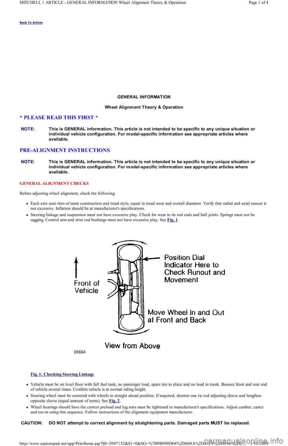
Steering linkage and suspension must not have excessive play. Check for wear in tie rod ends and ball joints. Springs must not be
sagging. Control arm and strut rod bushings must not have excessive play. See Fig. 1
.
Fig. 1: Checking Steering Linkage
Vehicle must be on level floor with full fuel tank, no passenger load, spare tire in place and no load in trunk. Bounce front and rear end
of vehicle several times. Confirm vehicle is at normal riding height.
Steering wheel must be centered with wheels in straight ahead position. If required, shorten one tie rod adjusting sleeve and lengthen
opposite sleeve (equal amount of turns). See Fig. 2
.
Wheel bearings should have the correct preload and lug nuts must be tightened to manufacturer's specifications. Adjust camber, caster
and toe-in using this sequence. Follow instructions of the alignment equipment manufacturer. NOTE:This is GENERAL inform ation. This article is not intended to be specific to any unique situation or
individual vehicle configuration. For m odel-specific inform ation see appropriate articles where
available.
NOTE:This is GENERAL inform ation. This article is not intended to be specific to any unique situation or
individual vehicle configuration. For m odel-specific inform ation see appropriate articles where
available.
CAUT ION: DO NOT attem pt to correct alignm ent by straightening parts. Dam aged parts MUST be replaced.
Page 1 of 4 MITCHELL 1 ARTICLE - GENERAL INFORMATION Wheel Alignment Theory & Operation
3/10/2009 http://www.eautorepair.net/app/PrintItems.asp?S0=2097152&S1=0&SG=%7B9B990D68%2D660A%2D45E9%2D8F46%2DE
...
Page 302 of 454
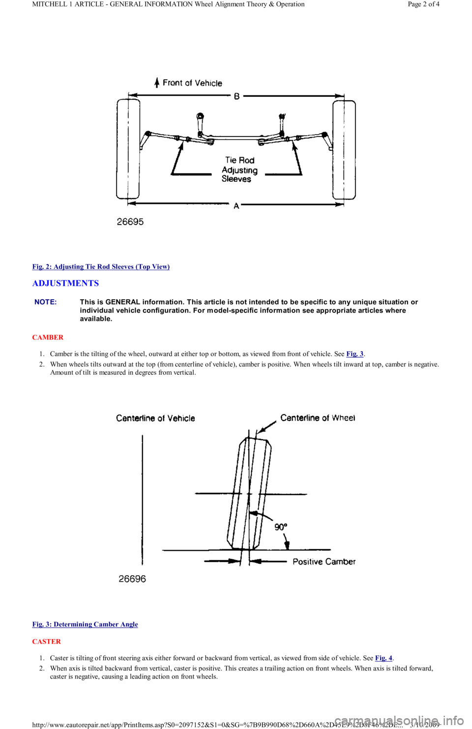
Fig. 2: Adjusting Tie Rod Sleeves (Top View)
ADJUSTMENTS
CAMBER
1. Camber is the tilting of the wheel, outward at either top or bottom, as viewed from front of vehicle. See Fig. 3
.
2. When wheels tilts outward at the top (from centerline of vehicle), camber is positive. When wheels tilt inward at top, camber is negative.
Amount of tilt is measured in degrees from vertical.
Fig. 3: Determining Camber Angle
CASTER
1. Caster is tilting of front steering axis either forward or backward from vertical, as viewed from side of vehicle. See Fig. 4
.
2. When axis is tilted backward from vertical, caster is positive. This creates a trailing action on front wheels. When axis is tilted forward,
caster is negative, causing a leading action on front wheels.
NOTE:This is GENERAL inform ation. This article is not intended to be specific to any unique situation or
individual vehicle configuration. For m odel-specific inform ation see appropriate articles where
available.
Page 2 of 4 MITCHELL 1 ARTICLE - GENERAL INFORMATION Wheel Alignment Theory & Operation
3/10/2009 http://www.eautorepair.net/app/PrintItems.asp?S0=2097152&S1=0&SG=%7B9B990D68%2D660A%2D45E9%2D8F46%2DE
...
Page 303 of 454
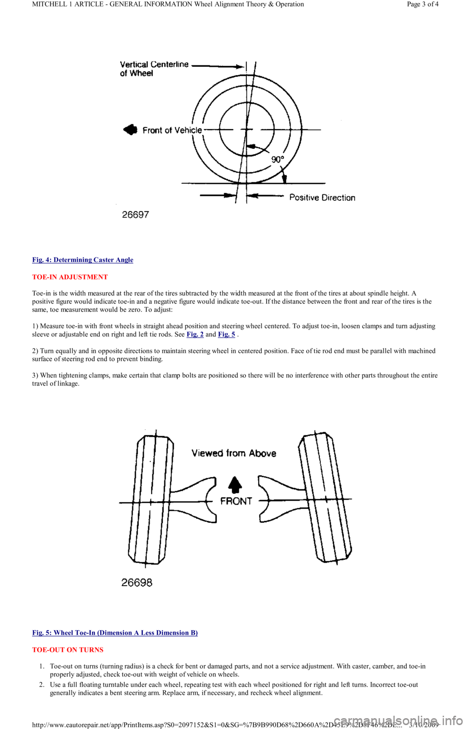
Fig. 4: Determining Caster Angle
TOE-IN ADJUSTMENT
Toe-in is the width measured at the rear of the tires subtracted by the width measured at the front of the tires at about spindle height. A
positive figure would indicate toe-in and a negative figure would indicate toe-out. If the distance between the front and rear of the tires is the
same, toe measurement would be zero. To adjust:
1) Measure toe-in with front wheels in straight ahead position and steering wheel centered. To adjust toe-in, loosen clamps and turn adjusting
sleeve or adjustable end on right and left tie rods. See Fig. 2
and Fig. 5 .
2) Turn equally and in opposite directions to maintain steering wheel in centered position. Face of tie rod end must be parallel with machined
surface of steering rod end to prevent binding.
3) When tightening clamps, make certain that clamp bolts are positioned so there will be no interference with other parts throughout the entire
travel of linkage.
Fig. 5: Wheel Toe
-In (Dimension A Less Dimension B)
TOE-OUT ON TURNS
1. Toe-out on turns (turning radius) is a check for bent or damaged parts, and not a service adjustment. With caster, camber, and toe-in
properly adjusted, check toe-out with weight of vehicle on wheels.
2. Use a full floating turntable under each wheel, repeating test with each wheel positioned for right and left turns. Incorrect toe-out
generally indicates a bent steering arm. Replace arm, if necessary, and recheck wheel alignment.
Page 3 of 4 MITCHELL 1 ARTICLE - GENERAL INFORMATION Wheel Alignment Theory & Operation
3/10/2009 http://www.eautorepair.net/app/PrintItems.asp?S0=2097152&S1=0&SG=%7B9B990D68%2D660A%2D45E9%2D8F46%2DE
...
Page 304 of 454
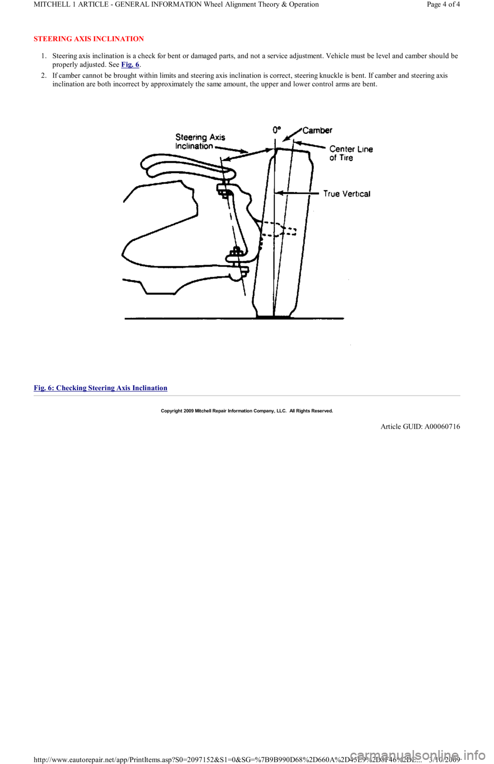
STEERING AXIS INCLINATION
1. Steering axis inclination is a check for bent or damaged parts, and not a service adjustment. Vehicle must be level and camber should be
properly adjusted. See Fig. 6
.
2. If camber cannot be brought within limits and steering axis inclination is correct, steering knuckle is bent. If camber and steering axis
inclination are both incorrect by approximately the same amount, the upper and lower control arms are bent.
Fig. 6: Checking Steering Axis Inclination
Copyr ight 2009 Mitchell Repair Information Company, LLC. All Rights Reserved.
Article GUID: A00060716
Page 4 of 4 MITCHELL 1 ARTICLE - GENERAL INFORMATION Wheel Alignment Theory & Operation
3/10/2009 http://www.eautorepair.net/app/PrintItems.asp?S0=2097152&S1=0&SG=%7B9B990D68%2D660A%2D45E9%2D8F46%2DE
...
Page 305 of 454
Back To Article
GENERAL INFORMATION
Manual Transmission Trouble Shooting
* PLEASE READ THIS FIRST *
INTRODUCTION
There are many times when the transmission is incorrectly blamed for shifting problems or noises that are actually caused by other reasons.
Shift difficulties are frequently caused by conditions outside of the transmission or transaxle. Typical conditions include: shift linkage, shift
cables, alignment of engine to transmission, worn engine mounts or clutch problems. Drive train noises may come from many sources such as
tires, road surfaces, wheel bearings, differentials, engine or exhaust system. Repairing or overhauling transmission will not cure these
problems.
No manufacturer makes a perfectly quiet transmission. Gear rollover noise is present in most constant mesh transmissions and will tend to
disappear when the clutch is disengaged or transmission is placed in gear. If clutch is properly adjusted, clutch release bearing noise will
disappear when release bearing is moved enough to slide release bearing away from pressure plate.
Trouble shooting can be helped by driving vehicle on a smooth level road to help eliminate tire and body noise. Note whether noise occurs on
acceleration, coasting, deceleration or steady driving conditions. Some problems may only occur when transmission is either hot or cold. Gear
lubricant that is too thick can cause hard shifting on cold mornings before engine is warm and vehicle has been driven.
MANUAL TRANSMISSION/TRANSAXLE TROUBLE SHOOTING NOTE:This is GENERAL inform ation. This article is not intended to be specific to any unique situation or
individual vehicle configuration. For m odel-specific inform ation see appropriate articles where
available.
NOTE:This is GENERAL inform ation. This article is not intended to be specific to any unique situation or
individual vehicle configuration. For m odel-specific inform ation see appropriate articles where
available.
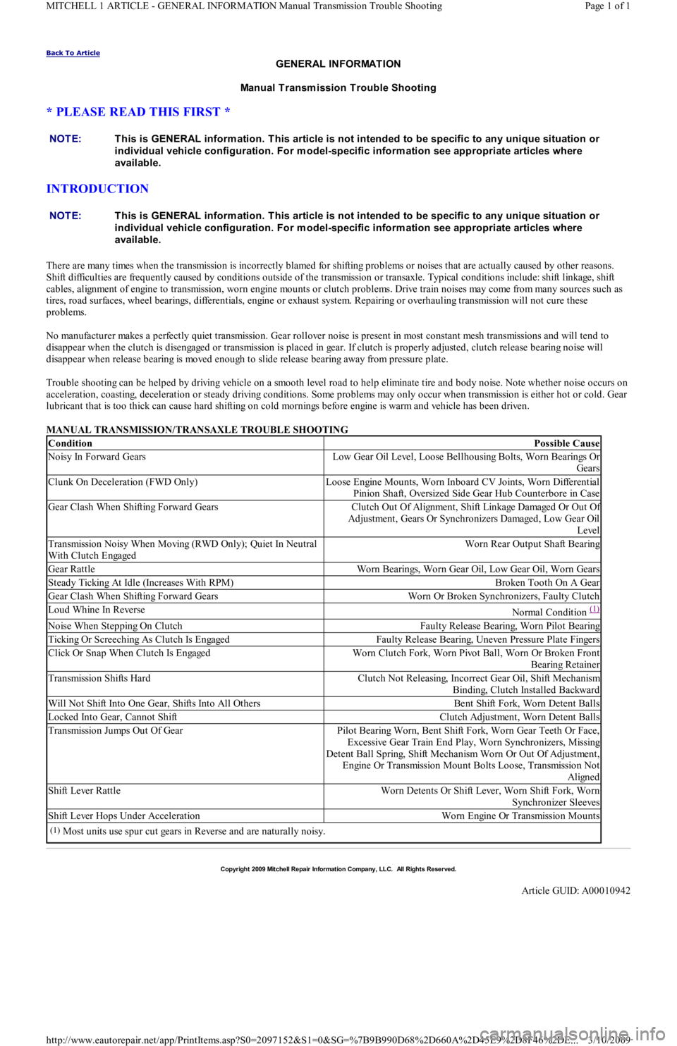
ConditionPossible Cause
Noisy In Forward GearsLow Gear Oil Level, Loose Bellhousing Bolts, Worn Bearings Or
Gears
Clunk On Deceleration (FWD Only)Loose Engine Mounts, Worn Inboard CV Joints, Worn Differential
Pinion Shaft, Oversized Side Gear Hub Counterbore in Case
Gear Clash When Shifting Forward GearsClutch Out Of Alignment, Shift Linkage Damaged Or Out Of
Adjustment, Gears Or Synchronizers Damaged, Low Gear Oil
Level
Transmission Noisy When Moving (RWD Only); Quiet In Neutral
With Clutch EngagedWorn Rear Output Shaft Bearing
Gear RattleWorn Bearings, Worn Gear Oil, Low Gear Oil, Worn Gears
Steady Ticking At Idle (Increases With RPM)Broken Tooth On A Gear
Gear Clash When Shifting Forward GearsWorn Or Broken Synchronizers, Faulty Clutch
Loud Whine In ReverseNormal Condition (1)
Noise When Stepping On ClutchFaulty Release Bearing, Worn Pilot Bearing
Ticking Or Screeching As Clutch Is EngagedFaulty Release Bearing, Uneven Pressure Plate Fingers
Click Or Snap When Clutch Is EngagedWorn Clutch Fork, Worn Pivot Ball, Worn Or Broken Front
Bearing Retainer
Transmission Shifts HardClutch Not Releasing, Incorrect Gear Oil, Shift Mechanism
Binding, Clutch Installed Backward
Will Not Shift Into One Gear, Shifts Into All OthersBent Shift Fork, Worn Detent Balls
Locked Into Gear, Cannot ShiftClutch Adjustment, Worn Detent Balls
Transmission Jumps Out Of GearPilot Bearing Worn, Bent Shift Fork, Worn Gear Teeth Or Face,
Excessive Gear Train End Play, Worn Synchronizers, Missing
Detent Ball Spring, Shift Mechanism Worn Or Out Of Adjustment,
Engine Or Transmission Mount Bolts Loose, Transmission Not
Aligned
Shift Lever RattleWorn Detents Or Shift Lever, Worn Shift Fork, Worn
Synchronizer Sleeves
Shift Lever Hops Under AccelerationWorn Engine Or Transmission Mounts
(1)Most units use spur cut gears in Reverse and are naturally noisy.
Copyr ight 2009 Mitchell Repair Information Company, LLC. All Rights Reserved.
Article GUID: A00010942
Page 1 of 1 MITCHELL 1 ARTICLE - GENERAL INFORMATION Manual Transmission Trouble Shooting
3/10/2009 http://www.eautorepair.net/app/PrintItems.asp?S0=2097152&S1=0&SG=%7B9B990D68%2D660A%2D45E9%2D8F46%2DE
...
Page 320 of 454
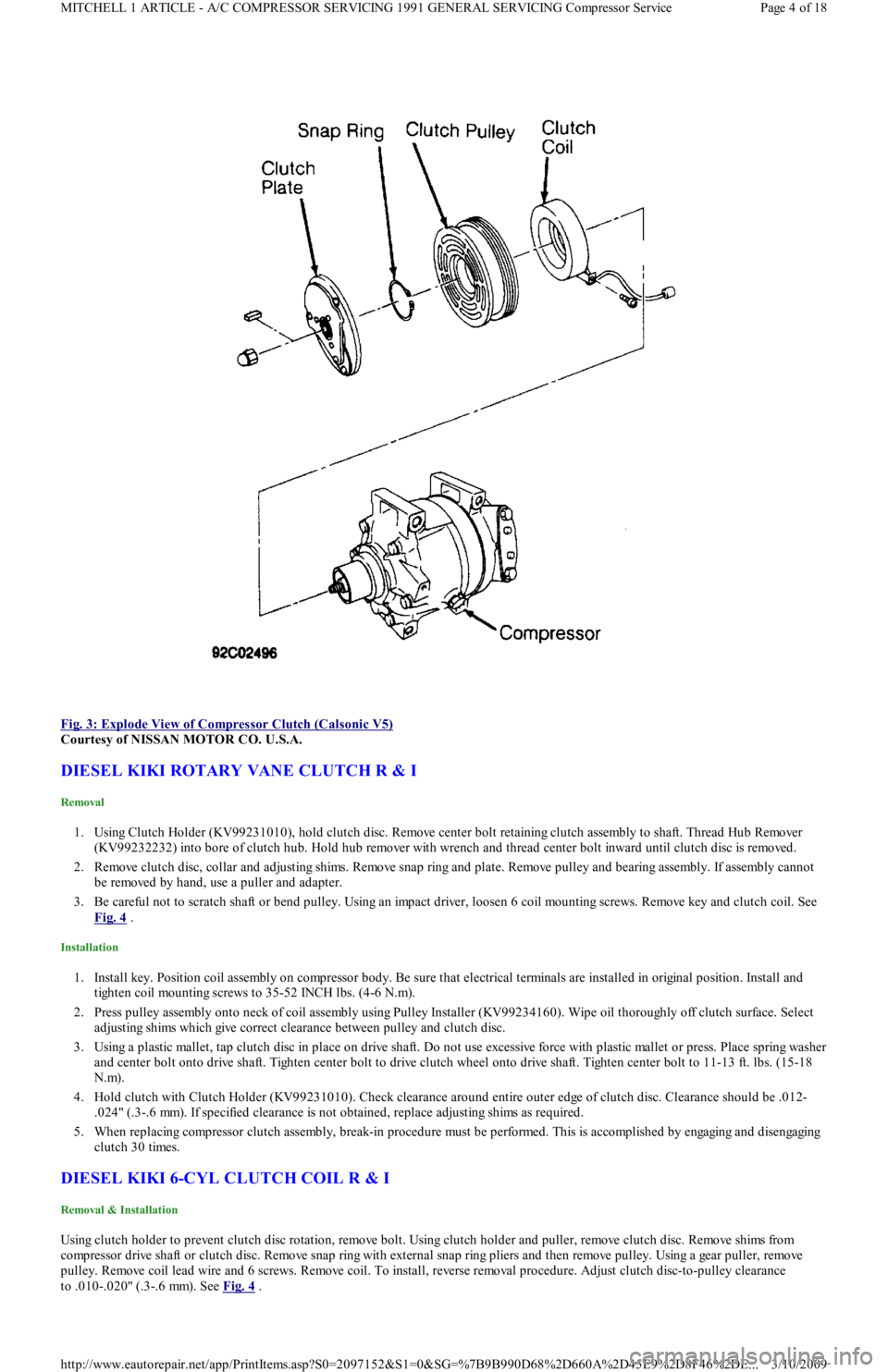
Fig. 3: Explode View of Compressor Clutch (Calsonic V5)
Courtesy of NISSAN MOTOR CO. U.S.A.
DIESEL KIKI ROTARY VANE CLUTCH R & I
Removal
1. Using Clutch Holder (KV99231010), hold clutch disc. Remove center bolt retaining clutch assembly to shaft. Thread Hub Remover
(KV99232232) into bore of clutch hub. Hold hub remover with wrench and thread center bolt inward until clutch disc is removed.
2. Remove clutch disc, collar and adjusting shims. Remove snap ring and plate. Remove pulley and bearing assembly. If assembly cannot
be removed by hand, use a puller and adapter.
3. Be careful not to scratch shaft or bend pulley. Using an impact driver, loosen 6 coil mounting screws. Remove key and clutch coil. See
Fig. 4
.
Installation
1. Install key. Position coil assembly on compressor body. Be sure that electrical terminals are installed in original position. Install and
tighten coil mounting screws to 35-52 INCH lbs. (4-6 N.m).
2. Press pulley assembly onto neck of coil assembly using Pulley Installer (KV99234160). Wipe oil thoroughly off clutch surface. Select
adjusting shims which give correct clearance between pulley and clutch disc.
3. Using a plastic mallet, tap clutch disc in place on drive shaft. Do not use excessive force with plastic mallet or press. Place spring washer
and center bolt onto drive shaft. Tighten center bolt to drive clutch wheel onto drive shaft. Tighten center bolt to 11-13 ft. lbs. (15-18
N.m).
4. Hold clutch with Clutch Holder (KV99231010). Check clearance around entire outer edge of clutch disc. Clearance should be .012-
.024" (.3-.6 mm). If specified clearance is not obtained, replace adjusting shims as required.
5. When replacing compressor clutch assembly, break-in procedure must be performed. This is accomplished by engaging and disengagin g
clutch 30 times.
DIESEL KIKI 6-CYL CLUTCH COIL R & I
Removal & Installation
Using clutch holder to prevent clutch disc rotation, remove bolt. Using clutch holder and puller, remove clutch disc. Remove shims from
compressor drive shaft or clutch disc. Remove snap ring with external snap ring pliers and then remove pulley. Using a gear puller, remove
pulley. Remove coil lead wire and 6 screws. Remove coil. To install, reverse removal procedure. Adjust clutch disc-to-pulley clearance
to .010-.020" (.3-.6 mm). See Fig. 4
.
Page 4 of 18 MITCHELL 1 ARTICLE - A/C COMPRESSOR SERVICING 1991 GENERAL SERVICING Compressor Service
3/10/2009 http://www.eautorepair.net/app/PrintItems.asp?S0=2097152&S1=0&SG=%7B9B990D68%2D660A%2D45E9%2D8F46%2DE
...