1991 FORD FESTIVA fuel
[x] Cancel search: fuelPage 140 of 454

FLV
Fill Limit Valve
FR
Fill Pipe Restrictor
FVV
Fuel Vapor Valve
HO2S
Heated Oxygen Sensor
MFI
Multiport Fuel Injection
MFI-MAF
MFI Mass Airflow Sensor
MIL
Malfunction Indicator Light
OC
Oxidation Catalytic Converter
OHC
Overhead Cam
ORVR
On-Board Refueling Vapor Recovery
ORVR-COV
ORVR Cut-Off Valve
ORVR-CV
ORVR Control Valve
ORVR-FMV
ORVR Flow Management Valve
ORVR-FTVCV
ORVR Fuel Tank Vapor Control Valve
ORVR-FTVRV
ORVR Fuel Tank Vapor Recirculation Valve
ORVR-LV
ORVR Leveling Valve
ORVR-OCKV
ORVR Overfill Check Valve
ORVR-RCV
ORVR Refueling Control Valve
ORVR-VCV
ORVR Vapor Cut Valve
ORVR-VRV
ORVR Vapor Recirculating Valve
Page 8 of 9 MITCHELL 1 ARTICLE - EMISSION CONTROL APPLICATIONS Emission Applications - Ford Motor Co. - Imports (1968-
...
3/10/2009 http://www.eautorepair.net/app/PrintItems.asp?S0=2097152&S1=0&SG=%7B7DD6473C%2DB5BB%2D4F20%2D9D70%2D
...
Page 141 of 454

ORVR-VSV
ORVR Vent Shut Valve
ORVR-VV
ORVR Vent Valve
OVCV
Outer Vent Control Valve
O2S
Oxygen Sensor
PAIR
Pulsed Secondary Air Injection
PCV
Positive Crankcase Ventilation
SFI
Sequential Multiport Fuel Injection
SFI-MAF
SFI Mass Airflow Sensor
SPK
Spark Controls
SPK-AVM
SPK Advance Vacuum Modulator
SPK-BVSV
SPK Bimetal Vacuum Switching Valve
SPK-CC
SPK Computer Controlled
SPK-CKV
SPK Check Valve
TWC
Three-Way Catalytic Converter
Copyr ight 2009 Mitchell Repair Information Company, LLC. All Rights Reserved.
Article GUID: A00157498
Page 9 of 9 MITCHELL 1 ARTICLE - EMISSION CONTROL APPLICATIONS Emission Applications - Ford Motor Co. - Imports (1968-
...
3/10/2009 http://www.eautorepair.net/app/PrintItems.asp?S0=2097152&S1=0&SG=%7B7DD6473C%2DB5BB%2D4F20%2D9D70%2D
...
Page 147 of 454

ELECTRONIC CONTROL ASSEMBLY (ECA)
REMOVAL & INSTALLATION
Disconnect negative battery cable. On Festiva, from under instrument panel, remove heater duct. On Capri, disengage push-pin retainers by
pulling back on front edges of both center carpet panels. Remove carpet panel retaining screws and panels. Disconnect ECA wire harness
connector. Remove ECA bolts and ECA. To install, reverse removal procedure. On Festiva, ensure mounting clip is inserted into bulkhead
recess.
FUEL SYSTEM
FUEL SYSTEM PRESSURE RELEASE
Remove rear seat assembly. With engine running, disconnect fuel pump connector. Run engine until it stalls to relieve fuel line pressure.
FUEL INJECTORS
Removal
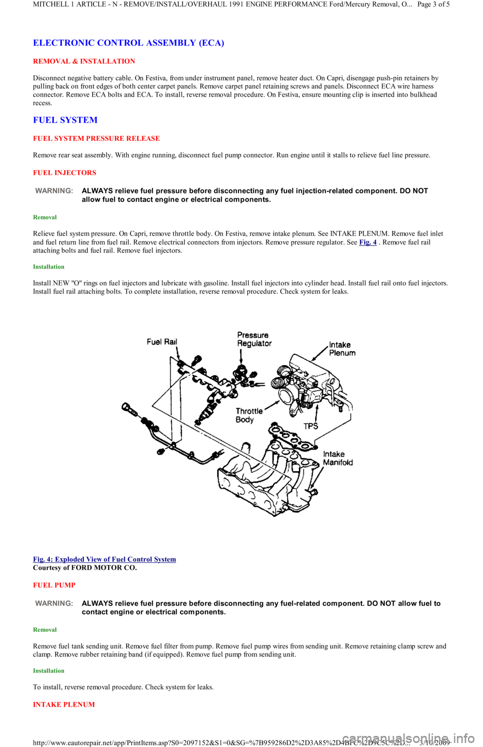
Relieve fuel system pressure. On Capri, remove throttle body. On Festiva, remove intake plenum. See INTAKE PLENUM. Remove fuel inlet
and fuel return line from fuel rail. Remove electrical connectors from injectors. Remove pressure regulator. See Fig. 4
. Remove fuel rail
attaching bolts and fuel rail. Remove fuel injectors.
Installation
Install NEW "O" rings on fuel injectors and lubricate with gasoline. Install fuel injectors into cylinder head. Install fuel rail onto fuel injectors.
Install fuel rail attaching bolts. To complete installation, reverse removal procedure. Check system for leaks.
Fig. 4: Exploded View of Fuel Control System
Courtesy of FORD MOTOR CO.
FUEL PUMP
Removal
Remove fuel tank sending unit. Remove fuel filter from pump. Remove fuel pump wires from sending unit. Remove retaining clamp screw and
clamp. Remove rubber retaining band (if equipped). Remove fuel pump from sending unit.
Installation
To install, reverse removal procedure. Check system for leaks.
INTAKE PLENUM WARNING:ALWAYS relieve fuel pressure before disconnecting any fuel injection-related com ponent. DO NOT
allow fuel to contact engine or electrical com ponents.
WARNING:ALWAYS relieve fuel pressure before disconnecting any fuel-related com ponent. DO NOT allow fuel to
contact engine or electrical com ponents.
Page 3 of 5 MITCHELL 1 ARTICLE - N - REMOVE/INSTALL/OVERHAUL 1991 ENGINE PERFORMANCE Ford/Mercury Removal, O
...
3/10/2009 http://www.eautorepair.net/app/PrintItems.asp?S0=2097152&S1=0&SG=%7B959286D2%2D3A85%2D4BFC%2D9C5C%2D
...
Page 149 of 454

VANE AIRFLOW (VAF) METER
Removal
1. Disconnect negative battery cable. On Capri, disconnect primary and secondary wires from coil. On Festiva, disconnect VAF wire
harness connector. Remove air duct.
2. On Capri, remove retaining bolt and ground wire from air cleaner cover. Remove air cleaner cover bolts and air cleaner cover. From
inside of air cleaner cover, remove VAF meter retaining nuts. On Festiva, remove attaching bolt and 4 nuts. Remove vane airflow met er.
Installation
To install, reverse removal procedure. Position new gasket over VAF mounting studs. Tighten bolts and nuts to specification, see TORQUE
SPECIFICATIONS at end of article.
TORQUE SPECIFICATIONS
TORQUE SPECIFICATIONS NOTE:For all on-vehicle adjustm ents not covered in this article, see ADJUST MENT S article in the ENGINE
PERFORMANCE Section.
ApplicationFt. Lbs. (N.m)
Coolant By-Pass Tube Outlet-To-Water Pump Bolts14-19 (19-26)
Distributor Mounting Bolts14-19 (19-26)
Exhaust Manifold Retaining Nuts29-42 (39-57)
Exhaust Pipe Nuts18-25 (24-34)
Fuel Line-To-Fuel Filter Bolt18-25 (24-34)
Fuel Pressure Regulator Nut(1)
Fuel Rail Retaining Bolt14-19 (19-26)
Heat Shield Bolts14-19 (19-26)
Intake Plenum Bolts/Nuts11-16 (15-22)
Oil Supply Line-To-Turbocharger Bolt12-17 (16-23)
Oxygen Sensor(1)
Power Steering Pump Bracket-To-Engine Bolts/Nut35-48 (47-65)
Throttle Body Bolt/Nuts12-17 (16-23)
Turbocharger Support Bracket Bolts32-45 (43-61)
Turbocharger-To-Exhaust Manifold Nuts20-25 (27-34)
INCH Lbs. (N.m)
Barometric Pressure (BP) Sensor Nut54-84 (6-9)
MAP Sensor Nuts54-84 (6-9)
Oil Supply Line-To-Engine Block Bolt104-156 (12-18)
Vane Airflow Meter Nuts110-152 (12-18)
(1)Information not available from manufacturer.
Copyr ight 2009 Mitchell Repair Information Company, LLC. All Rights Reserved.
Article GUID: A00022705
Page 5 of 5 MITCHELL 1 ARTICLE - N - REMOVE/INSTALL/OVERHAUL 1991 ENGINE PERFORMANCE Ford/Mercury Removal, O
...
3/10/2009 http://www.eautorepair.net/app/PrintItems.asp?S0=2097152&S1=0&SG=%7B959286D2%2D3A85%2D4BFC%2D9C5C%2D
...
Page 152 of 454

Back To Article
1991 ENGINE PERFORMANCE
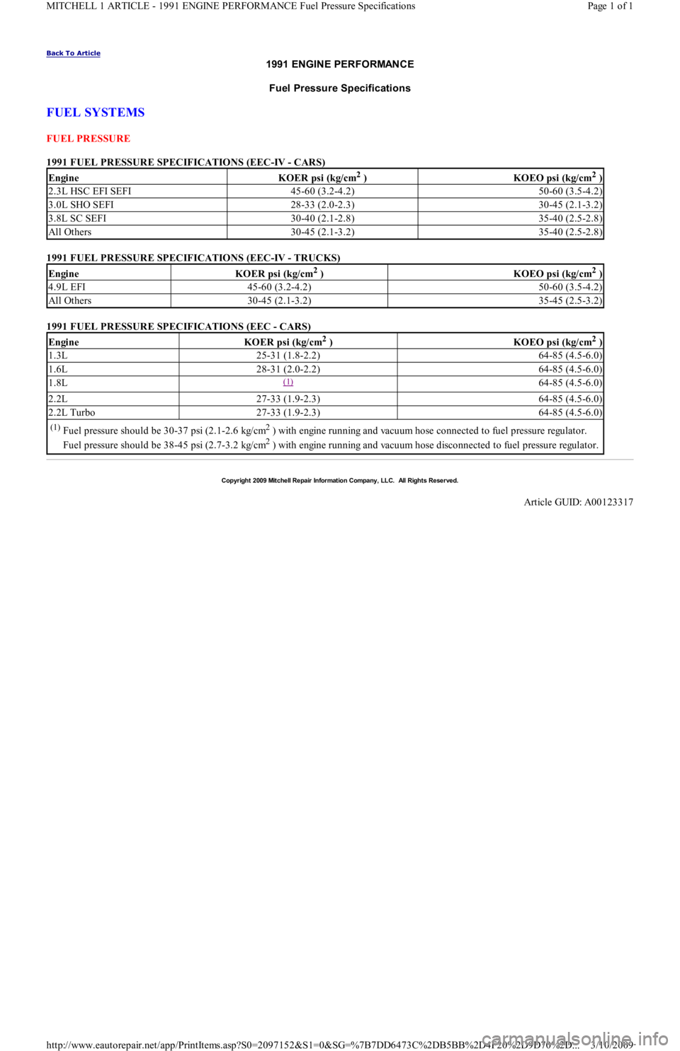
Fuel Pressure Specifications
FUEL SYSTEMS
FUEL PRESSURE
1991 FUEL PRESSURE SPECIFICATIONS (EEC-IV - CARS)
1991 FUEL PRESSURE SPECIFICATIONS (EEC-IV - TRUCKS)
1991 FUEL PRESSURE SPECIFICATIONS (EEC - CARS)
EngineKOER psi (kg/cm2 )KOEO psi (kg/cm2 )
2.3L HSC EFI SEFI45-60 (3.2-4.2)50-60 (3.5-4.2)
3.0L SHO SEFI28-33 (2.0-2.3)30-45 (2.1-3.2)
3.8L SC SEFI30-40 (2.1-2.8)35-40 (2.5-2.8)
All Others30-45 (2.1-3.2)35-40 (2.5-2.8)
EngineKOER psi (kg/cm2 )KOEO psi (kg/cm2 )
4.9L EFI45-60 (3.2-4.2)50-60 (3.5-4.2)
All Others30-45 (2.1-3.2)35-45 (2.5-3.2)
EngineKOER psi (kg/cm2 )KOEO psi (kg/cm2 )
1.3L25-31 (1.8-2.2)64-85 (4.5-6.0)
1.6L28-31 (2.0-2.2)64-85 (4.5-6.0)
1.8L(1) 64-85 (4.5-6.0)
2.2L27-33 (1.9-2.3)64-85 (4.5-6.0)
2.2L Turbo27-33 (1.9-2.3)64-85 (4.5-6.0)
(1)Fuel pressure should be 30-37 psi (2.1-2.6 kg/cm2 ) with engine running and vacuum hose connected to fuel pressure regulator.
Fuel pressure should be 38-45 psi (2.7-3.2 kg/cm
2 ) with engine running and vacuum hose disconnected to fuel pressure regulator.
Copyr ight 2009 Mitchell Repair Information Company, LLC. All Rights Reserved.
Article GUID: A00123317
Page 1 of 1 MITCHELL 1 ARTICLE - 1991 ENGINE PERFORMANCE Fuel Pressure Specifications
3/10/2009 http://www.eautorepair.net/app/PrintItems.asp?S0=2097152&S1=0&SG=%7B7DD6473C%2DB5BB%2D4F20%2D9D70%2D
...
Page 155 of 454

FUEL SYSTEM
FUEL PUMP
FUEL PUMP PERFORMANCE
INJECTOR RESISTANCE
FUEL INJECTOR RESISTANCE
IDLE SPEED
IDLE SPEED
(1)
THROTTLE POSITION SWITCH (TPS)
TPS ADJUSTMENT NOTE:For fuel pressure specifications, see FUEL PRESSURE SPECIFICAT IONS
article.
NOTE:Fuel pum p perform ance is a m easurem ent of fuel pressure and volum e availability, not regulated fuel
pressure.
ApplicationPressure -psi kg/cm2 )Min. Vol. in 10 sec. oz. (CC)
1.3L(1) 7.4 (220)
1.6L(1) 5.5 (167)
(1)For fuel pressure specifications, see FUEL PRESSURE SPECIFICATIONS article.
ApplicationOhms
1.3L & 1.6L12-16
ApplicationAuto. Trans.Man. Trans.
1.3L830-870680-720
1.6L800-900800-900
(1)With jumper wire connected between single-wire STI terminal and ground.
NOTE:Capri is equipped with throttle position sensor. No adjustm ent is required.
Test Condition (1) Cont. Between IDL-TLCont. Between PSW-TL
.02" (.5 mm)YesNo
.03" (.7 mm)NoNo
Wide Open ThrottleNoYes
(1)Insert specified feeler gauge between throttle adjustment screw and stop lever.
Copyr ight 2009 Mitchell Repair Information Company, LLC. All Rights Reserved.
Article GUID: A00022695
Page 3 of 3 MITCHELL 1 ARTICLE - C - SPECIFICATIONS 1991 ENGINE PERFORMANCE Ford/Mercury - Service & Adjustment Spe
...
3/10/2009 http://www.eautorepair.net/app/PrintItems.asp?S0=2097152&S1=0&SG=%7B7DD6473C%2DB5BB%2D4F20%2D9D70%2D
...
Page 156 of 454

Back To Article
F - BASIC TESTING
1991-92 ENGINE PERFORMANCE Ford Motor Co. Basic Diagnostic Procedures
INTRODUCTION
The following diagnostic steps help prevent overlooking simple problems and begin diagnosis for a no-start condition.
The first step in diagnosing any driveability problem is to verify the complaint. Test drive the vehicle under the conditions in which the
problem reportedly occurred.
Before entering self-diagnostics, perform a careful and complete visual inspection. Most engine control problems result from mechanical
breakdowns, poor electrical connections or damaged/misrouted vacuum hoses. Before condemning the computerized system, perform each test
listed in this article.
PRELIMINARY INSPECTION & ADJUSTMENTS
VISUAL INSPECTION
Perform a visual inspection of all electrical wiring. Look for chafed, stretched, cut or pinched wiring. Ensure electrical connections fit tightly
and are not corroded. Ensure vacuum hoses are properly routed and are not cut or pinched. If necessary, see VACUUM DIAGRAMS article in
the ENGINE PERFORMANCE Section to verify routing and connections. Inspect air induction system for possible vacuum leaks.
MECHANICAL INSPECTION
Compression
Engine mechanical condition can be checked using a compression gauge, vacuum gauge or engine analyzer. See engine analyzer instruction
manual for specific instructions. Lowest compression reading must be not less than 75 percent of highest reading.
Exhaust System Backpressure
Exhaust system can be checked with a vacuum gauge or a 0-5 psi pressure gauge. If a pressure gauge is used, remove O2 sensor. Connect gauge
to O2 sensor port. Start engine, and run at 2500 RPM. If exhaust system backpressure is more than 2 psi, exhaust system or catalytic converter
is plugged.
If a vacuum gauge is used, connect it to intake manifold vacuum. Start engine. Observe vacuum gauge. Open throttle part way and hold steady.
If vacuum gauge drops slowly after stabilizing, check exhaust system for a restriction.
FUEL PRESSURE
Fuel Pressure Release
Start engine (if possible), and unplug VAF meter connector. When engine stalls, turn ignition off and reconnect VAF meter wiring. Usin g sh o p
towel, cover fitting to absorb leakage when opening fuel system.
Fuel Pressure Check
1. Connect fuel pressure gauge between fuel filter and fuel rail. Open main valve, and close drain valve. Locate fuel pump check connector
in engine compartment, near left strut. Connect jumper wire between fuel pump test terminals (Black and Green/White wires on Capri
or Black and Green/Red wires on Festiva).
2. Turn ignition on to activate fuel pump. If pump does not run, check fuel pump circuit. If possible, start engine. Measure and record fuel
pressure. For fuel pressure specifications, see FUEL PRESSURE SPECIFICATIONS
article. Disconnect vacuum from pressure
regulator. Turn engine off. Wait 5 minutes and ensure residual pressure is at least 21 psi (1.5 kg/cm
2 ).
3. Operate fuel pump by reconnecting jumper wire at fuel pump check connector. Check fuel pump performance. Pinch hose between
pressure gauge and fuel filter. Do not hold longer than necessary to check pressure.For fuel pressure specifications, see FUEL
PRESSURE SPECIFICATIONS article. If pump does not meet specifications, check fuel pump circuit, fuel pump, fuel tank and fuel
filter or replace fuel pump.
FUEL PUMP PERFORMANCE NOTE:Unless stated otherwise in test procedure, perform all voltage tests with a Digital Volt-Ohm m eter
(DVOM) with a m inim um 10-m egohm input im pedance.
CAUT ION: DO NOT use ignition switch during com pression tests on fuel injected vehicles. Fuel injectors are
triggered by ignition switch during cranking m ode. Use a rem ote starter to crank engine to prevent fire
hazard and catalytic converter and engine oiling system contam ination.
WARNING:ALWAYS relieve fuel pressure before disconnecting any fuel injection system com ponent. DO NOT
allow fuel to contact engine or electrical com ponents.
NOTE:For 1991 fuel pressure specifications, see FUEL PRESSURE SPECIFICAT IONS
article. For 1992 fuel
pressure specifications, see FUEL PRESSURE SPECIFICAT IONS
article.
ApplicationPressure psi (kg/cm2 )Min. Vol. in 10 sec. Ozs. (cc)
Capri(1) 5.5 (167)
Festiva(1) 7.4 (220)
Page 1 of 4 MITCHELL 1 ARTICLE - F - BASIC TESTING 1991-92 ENGINE PERFORMANCE Ford Motor Co. Basic Diagnostic Proced
...
3/10/2009 http://www.eautorepair.net/app/PrintItems.asp?S0=2097152&S1=0&SG=%7B959286D2%2D3A85%2D4BFC%2D9C5C%2D
...
Page 157 of 454

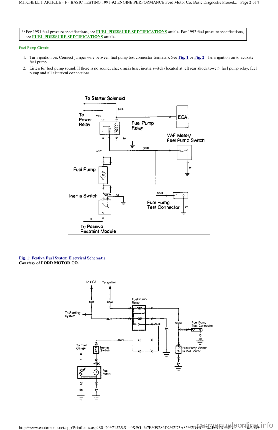
Fuel Pump Circuit
1. Turn ignition on. Connect jumper wire between fuel pump test connector terminals. See Fig. 1 or Fig. 2 . Turn ignition on to activate
fuel pump.
2. Listen for fuel pump sound. If there is no sound, check main fuse, inertia switch (located at left rear shock tower), fuel pump rel ay, fu el
pump and all electrical connections.
Fig. 1: Festiva Fuel System Electrical Schematic
Courtesy of FORD MOTOR CO.
(1)For 1991 fuel pressure specifications, see FUEL PRESSURE SPECIFICATIONS article. For 1992 fuel pressure specifications,
see FUEL PRESSURE SPECIFICATIONS
article.
Page 2 of 4 MITCHELL 1 ARTICLE - F - BASIC TESTING 1991-92 ENGINE PERFORMANCE Ford Motor Co. Basic Diagnostic Proced
...
3/10/2009 http://www.eautorepair.net/app/PrintItems.asp?S0=2097152&S1=0&SG=%7B959286D2%2D3A85%2D4BFC%2D9C5C%2D
...