1991 FORD FESTIVA bulb
[x] Cancel search: bulbPage 4 of 454
Turbo Boost Gauge Always Reads High
If turbo boost gauge always reads high, check these items:
Check for damaged White/Black signal wire.
Check for defective boost sensing unit.
Check for defective boost gauge.
Turbo Boost Gauge Inaccurate
If turbo boost gauge is inaccurate, check these items:
Check for loose or corroded connections.
Check for defective boost sensing unit.
Check for defective boost gauge.
TESTING
FUEL GAUGE SENDING UNIT
Capri
Remove rear seat cushion. Disconnect fuel pump/fuel gauge sending unit electrical connector at access cover. Turn ignition on. Fuel gauge
should read empty. Using a jumper wire, connect Yellow fuel gauge wire of vehicle harness connector to ground. Fuel gauge should read full.
If fuel gauge operates as specified, replace fuel gauge sending unit.
Festiva
Remove fuel gauge sending unit from tank. See FUEL SENDING UNIT under REMOVAL & INSTALLATION. Connect an ohmmeter and
check sending unit resistance as indicated in FUEL GAUGE SENDING UNIT RESISTANCE (FESTIVA)
table. Replace sending unit if
resistance is drastically different than specification.
FUEL GAUGE SENDING UNIT RESISTANCE (FESTIVA)
OIL PRESSURE GAUGE (CAPRI)
1. Remove electrical connector from oil pressure sending unit located on right side of engine block. Turn ignition switch on. Oil pressure
gauge should read low. Install a jumper wire between Yellow/Red wire of oil pressure sending unit vehicle harness connector and
ground. Oil pressure gauge should read high.
2. If oil pressure gauge operates as specified, replace sending unit. If gauge does not operate as specified, check instrument panel power
and ground circuits.
OIL PRESSURE WARNING LIGHT (FESTIVA)
Light Stays On With Engine Running
1. Turn ignition on (DO NOT start engine). Disconnect Yellow/Red wire from oil pressure switch connector. Light should go off.
2. If light stays on, repair short in Yellow/Red wire between oil indicator light and oil pressure switch. Reconnect wire to switch. Light
should be on with ignition on. If light does not go off when engine is started, check switch or engine for low oil pressure.
Oil Light Will Not Go On With Ignition On
1. Ground Yellow/Red wire at instrument panel connector. If light goes on, repair Yellow/Red wire between oil pressure switch and
indicator light or replace defective oil pressure switch.
2. If light does not illuminate, check bulb or check instrument panel ground circuit.
TEMPERATURE GAUGE (CAPRI)
1. Remove electrical connector from temperature sending unit located at front of cylinder head. Connect one lead of Gauge System Tester
(021-00055) to connector and other tester lead to ground. Set tester to 18 ohms, turn ignition switch on and observe temperature gauge.
Gauge should read 250°F.
2. Turn tester to 60 ohms. Gauge should read 175°F. Turn tester to 223 ohms. Gauge should read 100°F. If all readings are within twice
the needle width of correct reading, gauge is functioning properly. If readings are not as specified, replace gauge.
TEMPERATURE GAUGE (FESTIVA)
See TROUBLE SHOOTING for possible service areas.
TEMPERATURE SENDING UNIT (CAPRI)
Remove sending unit from engine and place in container of water. Heat water to 176°F (80°C). Measure resistance between sending unit
connector and case. Resistance should be 49.3-57.7 ohms. If resistance is not as specified, replace sending unit. NOTE:Inspect fuel tank for distortion or dam age. If distorted or dam aged, repair or replace tank before testing.
Float PositionOhms
Full Position (Up)Approximately 7
Half-Full Position (Middle)Approximately 33
Empty Position (Down)Approximately 95
Page 3 of 5 MITCHELL 1 ARTICLE - INSTRUMENT PANEL 1991 ACCESSORIES & SAFETY EQUIPMENT Ford Motor Co. Switches
...
3/10/2009 http://www.eautorepair.net/app/PrintItems.asp?S0=2097152&S1=0&SG=%7B959286D2%2D3A85%2D4BFC%2D9C5C%2D
...
Page 5 of 454

TURBO BOOST GAUGE & SENSOR (CAPRI)
1. Disconnect 3-pin boost sensor electrical connected located on right side of firewall. Turn ignition on. Measure voltage between
Yellow/Green and Black wires. Voltage should be greater than 10 volts. Turn ignition off. If voltage is greater than 10 volts, go t o n e xt
step. If voltage is 10 volts or less, repair Yellow/Green or Black wires as necessary.
2. Remove instrument panel. See INSTRUMENT PANEL
under REMOVAL & INSTALLATION. Disconnect instrument panel 8-pin
connector. With boost sensor disconnected, measure resistance through White/Black between instrument panel and boost sensor harness
connector. If resistance is less than 5 ohms, go to next step. If resistance is 5 ohms or more, repair or replace White/Black wire.
3. With 8-pin instrument panel connector disconnected, ground White/Black at boost gauge. Boost gauge should read low. Apply 12 vo l t s
to White/Black wire at boost gauge. Boost gauge should read high. If boost gauge operates as specified, go to next step. If boost gauge
does not operate as specified, replace boost gauge.
4. Reconnect instrument panel connectors (if removed). With ignition on and boost sensor disconnected, install jumper wire between
Yellow/Green and White/Black wires of boost sensor vehicle harness connector. Boost gauge should read high. If boost gauge reads
high, replace boost sensor. If boost gauge does not read high, go to TROUBLE SHOOTING
for other possible causes.
REMOVAL & INSTALLATION
INSTRUMENT PANEL
Removal & Installation (Capri)
1. Disconnect negative battery cable. Pull storage compartment from heater/radio bezel. Pull outward and remove trim covers located on
both sides of steering column. Remove retaining screws and carefully pull instrument panel bezel partially away from dash. Disconnect
electrical connectors from clock and switches in bezel. Remove instrument panel bezel.
2. Disconnect speedometer cable from transaxle. Remove instrument panel retaining screws and slide instrument panel outward. Press lock
tab and release speedometer cable from instrument panel. Remove electrical connectors from rear of instrument panel. Remove
instrument panel. To install instrument panel, reverse removal procedure.
Removal & Installation (Festiva)
1. Disconnect negative battery cable. Remove upper and lower steering column covers. Remove screws from panel bezel and remove bezel.
Disconnect rear wiper switch and rear defogger switch wiring harness connectors (if equipped).
2. Remove instrument panel-to-dash screws. Pull panel from dash. Reach behind panel and release speedometer drive cable lock tab. Lift
lock tabs and disconnect 2 electrical connectors from rear of panel. Remove panel. To install instrument panel, reverse removal
procedure.
INDICATOR LIGHTS
Removal & Installation
Remove instrument panel for access to indicator light bulbs. See INSTRUMENT PANEL under REMOVAL & INSTALLATION. To remove
bulb, rotate bulb counterclockwise to disengage locking tabs. When tabs release, pull bulb from printed circuit board. To install bulb, reverse
removal procedure. Install instrument panel and test lights.
SPEEDOMETER R & I
Removal & Installation (Capri)
R e mo ve n e ga t ive b a t t e r y c a b l e . R e mo ve in st r u me n t p a n e l . S e e INSTRUMENT PANEL under REMOVAL & INSTALLATION. Disassemble
instrument panel and remove speedometer/tachometer/boost gauge assembly from instrument panel. To install, apply a 3/16" (4.6 mm) b al l o f
Silicone Damping Grease (D7AZ-19A331-A) into drive hole of speedometer head. Reverse removal procedure to complete installation.
Removal & Installation (Festiva)
R e mo ve n e ga t ive b a t t e r y c a b l e . R e mo ve in st r u me n t p a n e l . S e e INSTRUMENT PANEL under REMOVAL & INSTALLATION. Disassemble
instrument panel and remove speedometer head assembly from instrument panel. Speedometer is a separate module and can be removed
independently from gauges. To install, reverse removal procedure.
SPEED SENSOR
On vehicles equipped with speed control, a speed sensor is mounted in speedometer head assembly. If replacement is necessary, speedometer
head assembly must be replaced. See SPEEDOMETER R & I
under REMOVAL & INSTALLATION.
FUEL GAUGE
Removal & Installation
Remo ve in st ru men t p an el . See INSTRUMENT PANEL under REMOVAL & INSTALLATION. Disassemble panel and remove fuel gauge.
To install gauge, reverse removal procedure. On Capri, the fuel/volt gauge must be replaced as an assembly.
FUEL SENDING UNIT
Removal & Installation
1. For Festiva, remove rear seat. For Capri, remove rear seat cushion. On Festiva, remove carpet hold-down pins and lift carpet for access
to sending unit access plate. On all models, remove access plate screws. NOTE:Federal law requires that a label stating the odom eter has been repaired or replaced be affixed to any
vehicle that has its odom eter repaired, replaced or set to zero.
Page 4 of 5 MITCHELL 1 ARTICLE - INSTRUMENT PANEL 1991 ACCESSORIES & SAFETY EQUIPMENT Ford Motor Co. Switches
...
3/10/2009 http://www.eautorepair.net/app/PrintItems.asp?S0=2097152&S1=0&SG=%7B959286D2%2D3A85%2D4BFC%2D9C5C%2D
...
Page 8 of 454
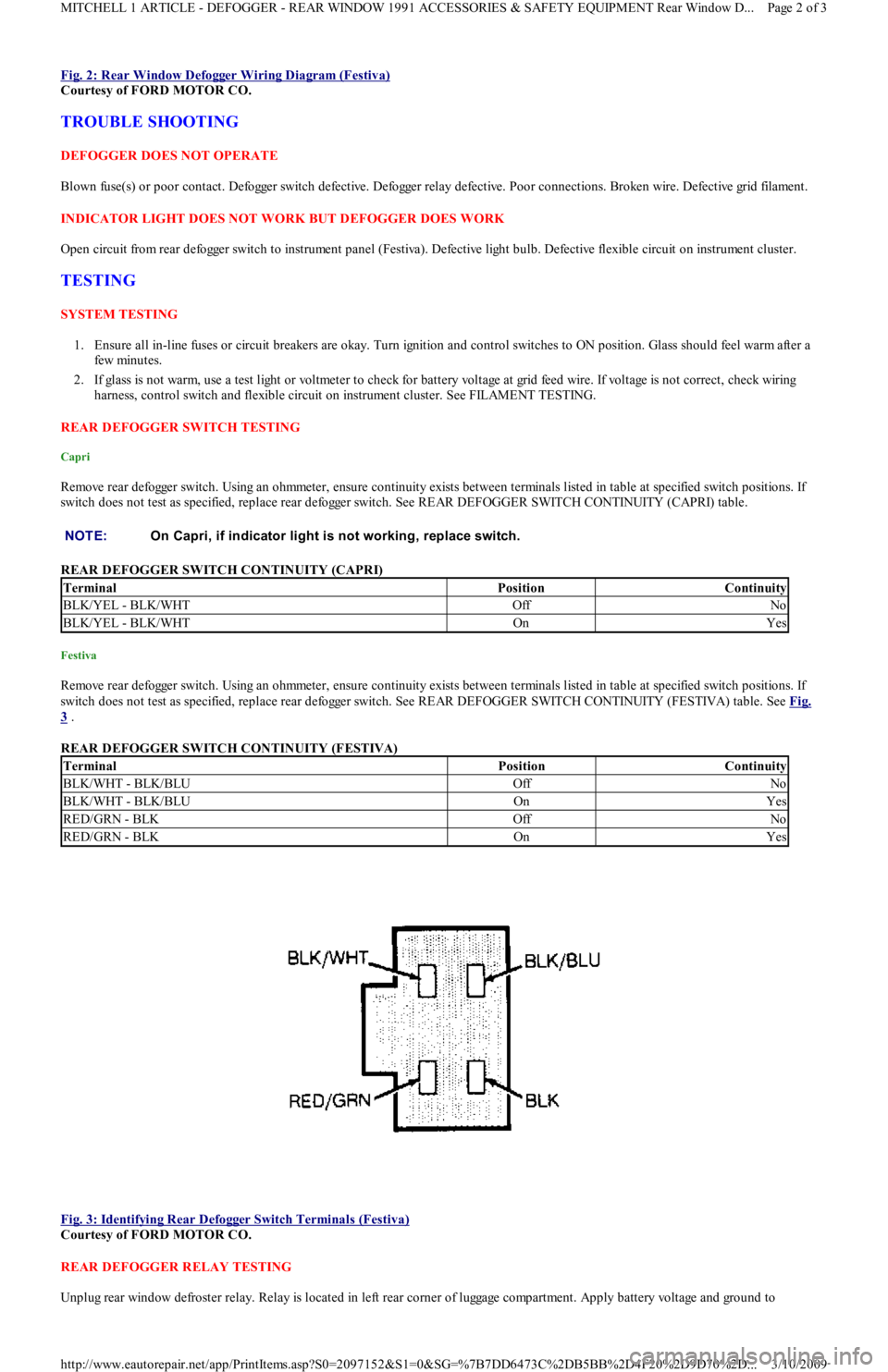
Fig. 2: Rear Window Defogger Wiring Diagram (Festiva)
Courtesy of FORD MOTOR CO.
TROUBLE SHOOTING
DEFOGGER DOES NOT OPERATE
Blown fuse(s) or poor contact. Defogger switch defective. Defogger relay defective. Poor connections. Broken wire. Defective grid filament.
INDICATOR LIGHT DOES NOT WORK BUT DEFOGGER DOES WORK
Open circuit from rear defogger switch to instrument panel (Festiva). Defective light bulb. Defective flexible circuit on instrument cluster.
TESTING
SYSTEM TESTING
1. Ensure all in-line fuses or circuit breakers are okay. Turn ignition and control switches to ON position. Glass should feel warm after a
few min u t es.
2. If glass is not warm, use a test light or voltmeter to check for battery voltage at grid feed wire. If voltage is not correct, check wiring
harness, control switch and flexible circuit on instrument cluster. See FILAMENT TESTING.
REAR DEFOGGER SWITCH TESTING
Capri
Remove rear defogger switch. Using an ohmmeter, ensure continuity exists between terminals listed in table at specified switch positions. If
switch does not test as specified, replace rear defogger switch. See REAR DEFOGGER SWITCH CONTINUITY (CAPRI) table.
REAR DEFOGGER SWITCH CONTINUITY (CAPRI)
Festiva
Remove rear defogger switch. Using an ohmmeter, ensure continuity exists between terminals listed in table at specified switch positions. If
switch does not test as specified, replace rear defogger switch. See REAR DEFOGGER SWITCH CONTINUITY (FESTIVA) table. See Fig.
3 .
REAR DEFOGGER SWITCH CONTINUITY (FESTIVA)
Fig. 3: Identifying Rear Defogger Switch Terminals (Festiva)
Courtesy of FORD MOTOR CO.
REAR DEFOGGER RELAY TESTING
Unplug rear window defroster relay. Relay is located in left rear corner of luggage compartment. Apply battery voltage and ground to NOTE:On Capri, if indicator light is not working, replace switch.
TerminalPositionContinuity
BLK/YEL - BLK/WHTOffNo
BLK/YEL - BLK/WHTOnYes
TerminalPositionContinuity
BLK/WHT - BLK/BLUOffNo
BLK/WHT - BLK/BLUOnYes
RED/GRN - BLKOffNo
RED/GRN - BLKOnYes
Page 2 of 3 MITCHELL 1 ARTICLE - DEFOGGER - REAR WINDOW 1991 ACCESSORIES & SAFETY EQUIPMENT Rear Window D
...
3/10/2009 http://www.eautorepair.net/app/PrintItems.asp?S0=2097152&S1=0&SG=%7B7DD6473C%2DB5BB%2D4F20%2D9D70%2D
...
Page 51 of 454
CATALYTIC CONVERTER
Continued operation of vehicle with a severe malfunction could cause converter to overheat, resulting in possible damage to converter and
ve h ic l e .
Any modification to the exhaust system on turbo models, which reduces exhaust backpressure, will lead to lean fuel mixtures and excessive
spark advance. This could cause serious engine damage.
ELECTROSTATIC DISCHARGE SENSITIVE (ESD) PARTS
ENGINE OIL
FUEL PUMP SHUTOFF SWITCH
This switch stops flow of fuel to engine after a collision. The impact does not have to be great for switch to be triggered. Switch must be reset
after collision. Switch is located under left rear speaker in luggage compartment. Press button to reset switch.
FUEL SYSTEM SERVICE
HALOGEN BULBS
PASSIVE RESTRAINTS
RADIATOR CAP
RADIATOR FAN WARNING:Many solid state electrical com ponents can be dam aged by static electricity (ESD). Som e will display a
warning label, but m any will not. Discharge personal static electricity by touching a m etal ground point
on the vehicle prior to servicing any ESD sensitive com ponent.
CAUT ION: Never use non-detergent or straight m ineral oil.
WARNING:Relieve fuel system pressure prior to servicing any fuel system com ponent (fuel injection m odels).
WARNING:Halogen bulbs contain pressurized gas which m ay explode if overheated. DO NOT touch glass portion
of bulb with bare hands. Eye protection should be worn when handling or working around halogen
bulbs.
CAUT ION: Before operating vehicle, securely fasten passive shoulder restraints to the em ergency release buckles.
T he buckle fits in only one way. Ensure to position it properly.
CAUT ION: Always disconnect the fan m otor when working near the radiator fan. T he fan is tem perature controlled
and could start at any tim e even when the ignition key is in the OFF position. DO NOT loosen or rem ove
radiator cap when cooling system is hot.
WARNING:Keep hands away from radiator fan. Fan is controlled by a therm ostatic switch which m ay com e on or
run for up to 15 m inutes even after engine is turned off.
Copyr ight 2009 Mitchell Repair Information Company, LLC. All Rights Reserved.
Article GUID: A00058075
Page 3 of 3 MITCHELL 1 ARTICLE - FUSES & CIRCUIT BREAKERS Fuses & Circuit Breakers 1988-93 Festiva
3/10/2009 http://www.eautorepair.net/app/PrintItems.asp?S0=2097152&S1=0&SG=%7B7DD6473C%2DB5BB%2D4F20%2D9D70%2D
...
Page 214 of 454
Back To Article
GENERAL INFORMATION
T rouble Shooting - Basic Procedures
* PLEASE READ THIS FIRST *
ACCESSORIES & ELECTRICAL
CHARGING SYSTEM TROUBLE SHOOTING
BASIC CHARGING SYSTEM TROUBLE SHOOTING CHART NOTE:This is GENERAL inform ation. This article is not intended to be specific to any unique situation or
individual vehicle configuration. T he purpose of this T rouble Shooting inform ation is to provide a list
of com m on causes to problem sym ptom s. For m odel-specific T rouble Shooting, refer to SUBJECT ,
DIAGNOST IC, or T EST ING articles available in the section(s) you are accessing.
NOTE:This is GENERAL inform ation. This article is not intended to be specific to any unique situation or
individual vehicle configuration. T he purpose of this T rouble Shooting inform ation is to provide a list
of com m on causes to problem sym ptom s. For m odel-specific T rouble Shooting, refer to SUBJECT ,
DIAGNOST IC, or T EST ING articles available in the section(s) you are accessing.
CONDITION & POSSIBLE CAUSECORRECTION
Vehicle Will Not Start
Dead batteryCheck battery cells, alternator
belt tension and alternator
output
Loose or corroded battery connectionsCheck all charging system
connections
Ignition circuit or switch malfunctionCheck and replace as necessary
Alternator Light Stays On With Engine Running
Loose or worn alternator drive beltCheck alternator drive tension
and condition, See Belt
Adjustment in TUNE-UP article
in the TUNE-UP section
Loose alternator wiring connectionsCheck all charging system
connections
Short in alternator light wiringSee Indicator Warning Lights in
STANDARD INSTRUMENTS
in the ACCESSORIES &
EQUIPMENT section
Defective alternator stator or diodesSee Bench Tests in
ALTERNATOR article
Defective regulatorSee Regulator Check in
ALTERNATOR article
Alternator Light Stays Off With Ignition Switch ON
Blown fuseSee WIRING DIAGRAMS
Defective alternatorSee Testing in ALTERNATOR
article
Defective indicator light bulb or socketSee Indicator Warning Lights in
STANDARD INSTRUMENTS
in the ACCESSORIES &
EQUIPMENT section
Alternator Light Stays OFF With Ignition Switch ON
Short in alternator wiringSee On-Vehicle Tests in
ALTERNATOR article
Defective rectifier bridgeSee Bench Tests in
ALTERNATOR article
Lights or Fuses Burn Out Frequently
Defective alternator wiringSee On-Vehicle Tests in
ALTERNATOR article
Defective regulatorSee Regulator Check in
ALTERNATOR article
Defective batteryCheck and replace as necessary
Ammeter Gauge Shows Discharge
Loose or worn drive beltCheck alternator drive belt
tension and condition. See Belt
Adjustment in TUNE-UP article
in the TUNE-UP section
Defective wiringCheck all wires and wire
Page 1 of 36 MITCHELL 1 ARTICLE - GENERAL INFORMATION Trouble Shooting - Basic Procedures
3/10/2009 http://www.eautorepair.net/app/PrintItems.asp?S0=2097152&S1=0&SG=%7B9B990D68%2D660A%2D45E9%2D8F46%2DE
...
Page 272 of 454
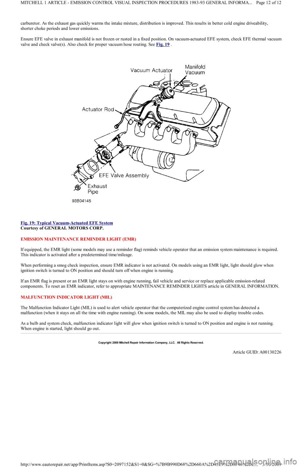
carburetor. As the exhaust gas quickly warms the intake mixture, distribution is improved. This results in better cold engine driveability,
shorter choke periods and lower emissions.
Ensure EFE valve in exhaust manifold is not frozen or rusted in a fixed position. On vacuum-actuated EFE system, check EFE thermal vacuu
m
valve and check valve(s). Also check for proper vacuum hose routing. See Fig. 19
.
Fig. 19: Typical Vacuum
-Actuated EFE System
Courtesy of GENERAL MOTORS CORP.
EMISSION MAINTENANCE REMINDER LIGHT (EMR)
If equipped, the EMR light (some models may use a reminder flag) reminds vehicle operator that an emission system maintenance is required.
This indicator is activated after a predetermined time/mileage.
When performing a smog check inspection, ensure EMR indicator is not activated. On models using an EMR light, light should glow when
ignition switch is turned to ON position and should turn off when engine is running.
If an EMR flag is present or an EMR light stays on with engine running, fail vehicle and service or replace applicable emission-related
components. To reset an EMR indicator, refer to appropriate MAINTENANCE REMINDER LIGHTS article in GENERAL INFORMATION.
MALFUNCTION INDICATOR LIGHT (MIL)
The Malfunction Indicator Light (MIL) is used to alert vehicle operator that the computerized engine control system has detected a
malfunction (when it stays on all the time with engine running). On some models, the MIL may also be used to display trouble codes.
As a bulb and system check, malfunction indicator light will glow when ignition switch is turned to ON position and engine is not running.
When engine is started, light should go out.
Copyr ight 2009 Mitchell Repair Information Company, LLC. All Rights Reserved.
Article GUID: A00130226
Page 12 of 12 MITCHELL 1 ARTICLE - EMISSION CONTROL VISUAL INSPECTION PROCEDURES 1983-93 GENERAL INFORMA...
3/10/2009 http://www.eautorepair.net/app/PrintItems.asp?S0=2097152&S1=0&SG=%7B9B990D68%2D660A%2D45E9%2D8F46%2DE
...
Page 278 of 454
Back To Article
GENERAL INFORMATION
Parasitic Load Explanation & T est Procedures
* PLEASE READ THIS FIRST *
GENERAL INFORMATION
The term Parasitic Load refers to electrical devices that continue to use or draw current after the ignition switch is turned to OFF position. This
small amount of continuous battery draw is expressed in milliamps (mA). On Chrysler vehicles, a typical Parasitic Load should be no more
than 30 milliamps (0.030 amps). On Ford Motor Co. and General Motors vehicles produced after 1980, a typical Parasitic Load should be no
more than 50 milliamps (0.050 amps).
Vehicles produced since 1980 have memory devices that draw current with ignition off for as long as 20 minutes before shutting down the
Parasitic Drain. When Parasitic Load exceeds normal specifications, the vehicle may exhibit dead battery and no-start condition.
Follow test procedure for checking Parasitic Loads to completion. A brief overview of a suggested test procedure is included along with some
typical Parasitic Load specifications. Refer to GENERAL MOTORS PARASITIC LOAD TABLE chart.
TESTING FOR PARASITIC LOAD
The battery circuit must be opened to connect test switch (shunt) and ammeter into the circuit. When a battery cable is removed, timer circuits
within the vehicle computer are interrupted and immediately begin to discharge. If in doubt about the condition of the ammeter fuse, test it
with an ohmmeter prior to beginning test. An open fuse will show the same reading (00.00) as no parasitic drain. Begin test sequence with the
meter installed and on the 10-amp scale. Select lower scale to read parasitic draw.
CHRYSLER IGNITION OFF DRAW (IOD) TEST
To test for excessive IOD, verify that all electrical accessories are OFF. Turn off all lights, remove ignition key, and close all doors and decklid.
If the vehicle is equipped with electronic accessories (illuminated entry, automatic load leveler, body computer, or high line radio), allow the
system to automatically shut off (time out), up to 3 minutes.
1. Raise the hood and disconnect both battery cables, negative first.
2. Reconnect the negative cable and connect a typical 12-volt test light (low wattage bulb) between the positive cable clamp and the
positive battery post. Remove the engine compartment lamp bulb. If the test light does not light, proceed to step 3
. If the test light does
light, proceed to step, 4
. The test light will indicate IOD greater than 3 amps. After higher amperage IOD has been corrected, proceed to
step 3
.
3. ith 12-volt test light still connected (not lit), connect an ammeter (milliampere scale) between the positive cable clamp and the positive
battery post, disconnect test light, refer to instructions provided with ammeter being used. A reading of 30 milliamperes or less indicates
normal electrical draw. If ammeter reads more than 30 milliamperes, excessive IOD must be corrected.
4. Locate the fuse panel and remove fuses or circuit breakers one at a time, and observe ammeter after each fuse or circuit breaker is
removed. If test light goes out and the reading drops below 30 milliamperes when a certain fuse or circuit breaker is removed, that circuit
may have a defect.
5. If IOD is detected after all fuses and circuit breakers have been removed, disconnect the 60-way connector at the Single Module Engine
Control (SMEC), located outboard of the battery.
6. If excessive IOD is detected after all fused circuits and SMEC have been verified, disconnect the B+ terminal from the alternat o r. If
reading drops below 30 milliamperes, reinstall all fuses and circuit breakers, reconnect B+ terminal at alternator, reconnect battery, and
perform alternator diagnostics.
7. Install engine compartment lamp bulb.
TEST PROCEDURE USING TEST SWITCH
1. Turn ignition off. Remove negative battery terminal cable. Install Disconnect Tool (J-38758) test switch male end to negative battery
cable. Turn test switch knob to OFF position (current through meter). Install negative battery cable to the female end of test switch. NOTE:This is GENERAL inform ation. This article is not intended to be specific to any unique situation or
individual vehicle configuration. For m odel-specific inform ation see appropriate articles where
available.
NOTE:This is GENERAL inform ation. This article is not intended to be specific to any unique situation or
individual vehicle configuration. For m odel-specific inform ation see appropriate articles where
available.
NOTE:This is GENERAL inform ation. This article is not intended to be specific to any unique situation or
individual vehicle configuration. For m odel-specific inform ation see appropriate articles where
available.
CAUT ION: Always turn ignition off when connecting or disconnecting battery cables, battery chargers or jum per
cables. DO NOT turn test switch to OFF position (which causes current to run through am m eter or
vehicle electrical system ).
NOTE:Mem ory functions of various accessories m ust be reset after the battery is reconnected.
CAUT ION: IOD greater than 3 am ps m ay dam age m illam pm eter.
Page 1 of 4 MITCHELL 1 ARTICLE - GENERAL INFORMATION Parasitic Load Explanation & Test Procedures
3/10/2009 http://www.eautorepair.net/app/PrintItems.asp?S0=2097152&S1=0&SG=%7B9B990D68%2D660A%2D45E9%2D8F46%2DE
...
Page 361 of 454
tube from evaporator core fins while removing thermostatic switch. To install, reverse removal procedure. Evacuate and recharge system.
THERMOSTATIC EXPANSION VALVE
Removal & Installation
1. Discharge A/C system using approved refrigerant recovery/recycling equipment. Remove evaporator housing. See EVAPORATOR
HOUSING under REMOVAL & INSTALLATION. Remove air inlet duct. See Fig. 1 .
2. Remove insulation from sensing bulb. Disconnect thermostatic expansion valve at evaporator tube fitting and inlet tube fitting (from
receiver-drier). See Fig. 3
. Remove thermostatic expansion valve. To install, reverse removal procedure. Use new "O" rings. Evacuate
and recharge system.
A/C RELAYS
Removal & Installation
A/C relays are located in left front corner of engine compartment, near battery. Unclip relay holder from its mounting bracket. Disconnect
relay wiring. DO NOT pull on wiring connector to remove relay from holder. Remove relay from holder. To install, reverse removal procedure.
A/C-HEATER CONTROL ASSEMBLY
Removal & Installation
1. A/C control module is located above radio. Remove accessory bezel. Remove radio (if necessary) and glove box. Disconnect
recirculated/fresh air cable from door lever. See Fig. 5
. Disconnect mode select cable from door lever. See Fig. 6 .
2. Disconnect temperature control cable from door lever. See Fig. 4
. Pull control assembly away from dash, and disconnect wiring
connectors. Remove control assembly.
3. To install, reverse removal procedure. Check and adjust temperature control, recirculated/fresh air and mode cables. See
ADJUSTMENTS. Test control assembly operation.
BLOWER MOTOR
Removal & Installation
Disconnect negative battery cable. Remove A/C air outlet duct located below steering column. See Fig. 2 . Disconnect blower motor wiring.
Remove blower motor attaching screws and blower motor. Remove blower wheel attaching nut. Remove blower wheel and washer. To install,
reverse removal procedure.
BLOWER MOTOR RESISTOR
Removal & Installation
Disconnect negative battery cable. Remove air duct located below steering column. See Fig. 2 . Disconnect blower motor resistor wiring.
Remove blower resistor attaching screws and resistor. To install, reverse removal procedure.
AIR DISTRIBUTION PLENUM
Removal & Installation
1. Remove instrument panel. See INSTRUMENT PANEL under REMOVAL & INSTALLATION. Drain cooling system. Disconnect
heater hoses in engine compartment. Disconnect wiring for blower motor and blower resistor. Disengage wiring harness and antenna
lead from bracket on front of air distribution housing.
2. Loosen connector duct-to-air inlet clamp screw. Remove upper and lower mounting nuts from plenum. Disengage and remove plenum
from defroster ducts. To install, reverse removal procedure. Refill cooling system, and check for leaks.
HEATER CORE
Removal & Installation
1. Remove air distribution plenum. See AIR DISTRIBUTION PLENUM under REMOVAL & INSTALLATION. Disconnect linkage
connecting defroster doors. Remove attaching screw located near blower resistor. Turn housing around and remove attaching screw
located near blower motor opening.
2. Remove clips retaining blower housing halves. Separate blower housing halves. Remove heater core. Remove tube insert from heater
core. To install, reverse removal procedure. Test system for proper operation.
INSTRUMENT PANEL
Removal & Installation
1. Disconnect negative battery cable. Remove steering wheel, steering column covers and multifunction switch assembly. Disconnect
electrical connectors from switches on instrument panel. Remove instrument cluster hood.
2. Disconnect speedometer cable from transmission. Remove 4 instrument cluster screws. Pull instrument cluster out from instrument
panel cluster enough to disconnect wiring and speedometer cable. Remove instrument cluster.
3. Remove steering column shield. Remove shield bracket. Remove glove box. Remove fuse panel cover and 4 fuse panel screws. Pull fu se
panel out, but DO NOT remove. Remove shift lever console and mount brackets. CAUTION: DO NOT rem ove screw in front of blower resistor, or blower resistor m ounting plate will fall into air
distribution plenum . T o retrieve plate, disassem ble instrum ent panel.
Page 13 of 14 MITCHELL 1 ARTICLE - 1991 AIR CONDITIONING & HEAT MANUAL A/C
3/10/2009 http://www.eautorepair.net/app/PrintItems.asp?S0=2097152&S1=0&SG=%7B9B990D68%2D660A%2D45E9%2D8F46%2DE
...