1991 FORD FESTIVA ect
[x] Cancel search: ectPage 393 of 454
Removal
1. Remove hub and knuckle assembly from vehicle. See HUB & KNUCKLE ASSEMBLY under REMOVAL & INSTALLATION. Using
Knuckle Puller (T87C-1104-A), or a press and bearing puller, remove drive hub/rotor assembly from steering knuckle/dust shield
assembly.
2. Remove bearing preload spacer from hub. Spacer is preselected to provide correct bearing preload. Ensure correct spacer is installed
during reassembly. Install hub/rotor assembly in a vise. Scribe alignment marks on hub and rotor for reassembly reference.
3. Remove rotor attaching bolts and rotor. Use Bearing Splitter (D84L-1123-A), Shaft Protector (D80L-625-2) and a press, or Bearing
Puller (D80L-927-A) and Puller Attachment (D84L-1123-A) to remove outer bearing from wheel hub. Remove and discard outer and
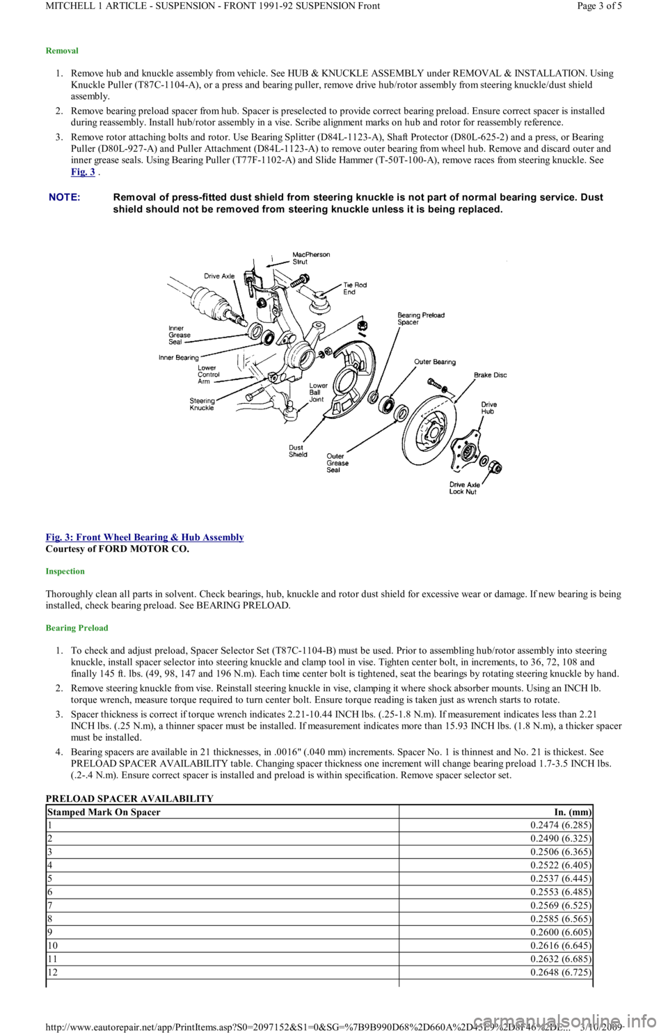
inner grease seals. Using Bearing Puller (T77F-1102-A) and Slide Hammer (T-50T-100-A), remove races from steering knuckle. See
Fig. 3
.
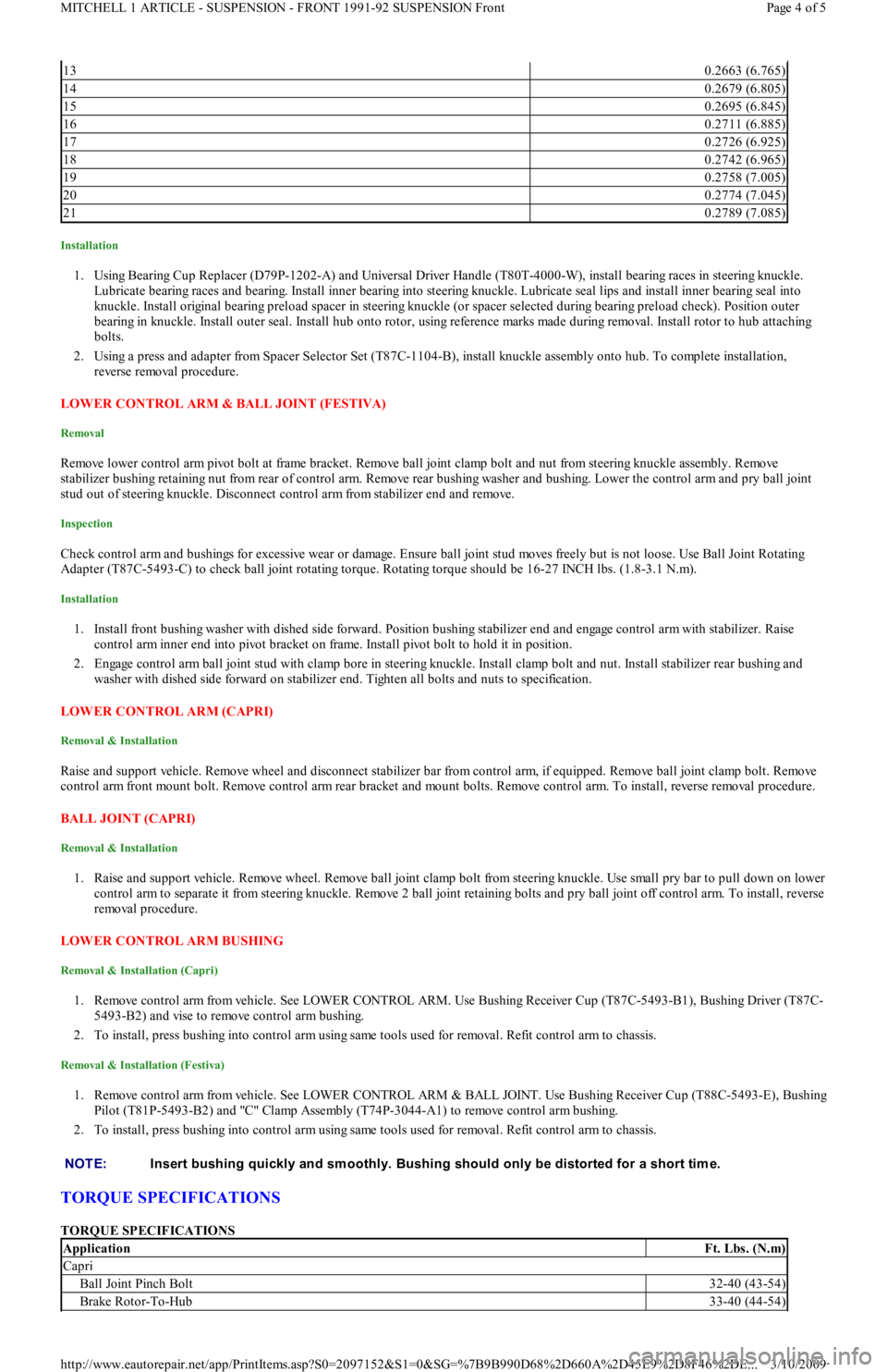
Fig. 3: Front Wheel Bearing & Hub Assembly
Courtesy of FORD MOTOR CO.
Inspection
Thoroughly clean all parts in solvent. Check bearings, hub, knuckle and rotor dust shield for excessive wear or damage. If new bearing is being
installed, check bearing preload. See BEARING PRELOAD.
Bearing Preload
1. To check and adjust preload, Spacer Selector Set (T87C-1104-B) must be used. Prior to assembling hub/rotor assembly into steering
knuckle, install spacer selector into steering knuckle and clamp tool in vise. Tighten center bolt, in increments, to 36, 72, 108 and
finally 145 ft. lbs. (49, 98, 147 and 196 N.m). Each time center bolt is tightened, seat the bearings by rotating steering knuckle by hand.
2. Remove steering knuckle from vise. Reinstall steering knuckle in vise, clamping it where shock absorber mounts. Using an INCH lb.
torque wrench, measure torque required to turn center bolt. Ensure torque reading is taken just as wrench starts to rotate.
3. Spacer thickness is correct if torque wrench indicates 2.21-10.44 INCH lbs. (.25-1.8 N.m). If measurement indicates less than 2.21
INCH lbs. (.25 N.m), a thinner spacer must be installed. If measurement indicates more than 15.93 INCH lbs. (1.8 N.m), a thicker spacer
must be installed.
4. Bearing spacers are available in 21 thicknesses, in .0016" (.040 mm) increments. Spacer No. 1 is thinnest and No. 21 is thickest. See
PRELOAD SPACER AVAILABILITY table. Changing spacer thickness one increment will change bearing preload 1.7-3.5 INCH lbs.
(.2-.4 N.m). Ensure correct spacer is installed and preload is within specification. Remove spacer selector set.
PRELOAD SPACER AVAILABILITY NOTE:Rem oval of press-fitted dust shield from steering knuckle is not part of norm al bearing service. Dust
shield should not be rem oved from steering knuckle unless it is being replaced.
Stamped Mark On SpacerIn. (mm)
10.2474 (6.285)
20.2490 (6.325)
30.2506 (6.365)
40.2522 (6.405)
50.2537 (6.445)
60.2553 (6.485)
70.2569 (6.525)
80.2585 (6.565)
90.2600 (6.605)
100.2616 (6.645)
110.2632 (6.685)
120.2648 (6.725)
Page 3 of 5 MITCHELL 1 ARTICLE - SUSPENSION - FRONT 1991-92 SUSPENSION Front
3/10/2009 http://www.eautorepair.net/app/PrintItems.asp?S0=2097152&S1=0&SG=%7B9B990D68%2D660A%2D45E9%2D8F46%2DE
...
Page 394 of 454
Installation
1. Using Bearing Cup Replacer (D79P-1202-A) and Universal Driver Handle (T80T-4000-W), install bearing races in steering knuckle.
Lubricate bearing races and bearing. Install inner bearing into steering knuckle. Lubricate seal lips and install inner bearing seal into
knuckle. Install original bearing preload spacer in steering knuckle (or spacer selected during bearing preload check). Position outer
bearing in knuckle. Install outer seal. Install hub onto rotor, using reference marks made during removal. Install rotor to hub attaching
bolts.
2. Using a press and adapter from Spacer Selector Set (T87C-1104-B), install knuckle assembly onto hub. To complete installation,
reverse removal procedure.
LOWER CONTROL ARM & BALL JOINT (FESTIVA)
Removal
Remove lower control arm pivot bolt at frame bracket. Remove ball joint clamp bolt and nut from steering knuckle assembly. Remove
stabilizer bushing retaining nut from rear of control arm. Remove rear bushing washer and bushing. Lower the control arm and pry ball joint
stud out of steering knuckle. Disconnect control arm from stabilizer end and remove.
Inspection
Check control arm and bushings for excessive wear or damage. Ensure ball joint stud moves freely but is not loose. Use Ball Joint Rotating
Adapter (T87C-5493-C) to check ball joint rotating torque. Rotating torque should be 16-27 INCH lbs. (1.8-3.1 N.m).
Installation
1. Install front bushing washer with dished side forward. Position bushing stabilizer end and engage control arm with stabilizer. Raise
control arm inner end into pivot bracket on frame. Install pivot bolt to hold it in position.
2. Engage control arm ball joint stud with clamp bore in steering knuckle. Install clamp bolt and nut. Install stabilizer rear bushing and
washer with dished side forward on stabilizer end. Tighten all bolts and nuts to specification.
LOWER CONTROL ARM (CAPRI)
Removal & Installation
Raise and support vehicle. Remove wheel and disconnect stabilizer bar from control arm, if equipped. Remove ball joint clamp bolt. Remove
control arm front mount bolt. Remove control arm rear bracket and mount bolts. Remove control arm. To install, reverse removal procedure.
BALL JOINT (CAPRI)
Removal & Installation
1. Raise and support vehicle. Remove wheel. Remove ball joint clamp bolt from steering knuckle. Use small pry bar to pull down on lower
control arm to separate it from steering knuckle. Remove 2 ball joint retaining bolts and pry ball joint off control arm. To install, reverse
removal procedure.
LOWER CONTROL ARM BUSHING
Removal & Installation (Capri)
1. Remove control arm from vehicle. See LOWER CONTROL ARM. Use Bushing Receiver Cup (T87C-5493-B1), Bushing Driver (T87C-
5493-B2) and vise to remove control arm bushing.
2. To install, press bushing into control arm using same tools used for removal. Refit control arm to chassis.
Removal & Installation (Festiva)
1. Remove control arm from vehicle. See LOWER CONTROL ARM & BALL JOINT. Use Bushing Receiver Cup (T88C-5493-E), Bushing
Pilot (T81P-5493-B2) and "C" Clamp Assembly (T74P-3044-A1) to remove control arm bushing.
2. To install, press bushing into control arm using same tools used for removal. Refit control arm to chassis.
TORQUE SPECIFICATIONS
TORQUE SPECIFICATIONS
130.2663 (6.765)
140.2679 (6.805)
150.2695 (6.845)
160.2711 (6.885)
170.2726 (6.925)
180.2742 (6.965)
190.2758 (7.005)
200.2774 (7.045)
210.2789 (7.085)
NOTE:Insert bushing quickly and sm oothly. Bushing should only be distorted for a short tim e.
ApplicationFt. Lbs. (N.m)
Capri
Ball Joint Pinch Bolt32-40 (43-54)
Brake Rotor-To-Hub33-40 (44-54)
Page 4 of 5 MITCHELL 1 ARTICLE - SUSPENSION - FRONT 1991-92 SUSPENSION Front
3/10/2009 http://www.eautorepair.net/app/PrintItems.asp?S0=2097152&S1=0&SG=%7B9B990D68%2D660A%2D45E9%2D8F46%2DE
...
Page 396 of 454
Back To Article
SUSPENSION - REAR
1991-92 SUSPENSION Rear
DESCRIPTION
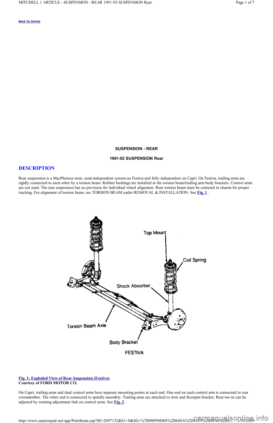
Rear suspension is a MacPherson strut, semi-independent system on Festiva and fully independent on Capri. On Festiva, trailing arms are
rigidly connected to each other by a torsion beam. Rubber bushings are installed at the torsion beam/trailing arm body brackets. Control arms
are not used. The rear suspension has no provision for individual wheel alignment. Rear torsion beam must be centered in chassis for proper
tracking. For alignment of torsion beam, see TORSION BEAM under REMOVAL & INSTALLATION. See Fig. 1
.
Fig. 1: Exploded View of Rear Suspension (Festiva)
Courtesy of FORD MOTOR CO.
On Capri, trailing arms and dual control arms have separate mounting points at each end. One end on each control arm is connected to rear
crossmember. The other end is connected to spindle assembly. Trailing arms are attached to strut and floorpan bracket. Rear toe-in can be
adjusted by rotating adjustment link on control arms. See Fig. 2
.
Page 1 of 7 MITCHELL 1 ARTICLE - SUSPENSION - REAR 1991-92 SUSPENSION Rear
3/10/2009 http://www.eautorepair.net/app/PrintItems.asp?S0=2097152&S1=0&SG=%7B9B990D68%2D660A%2D45E9%2D8F46%2DE
...
Page 397 of 454
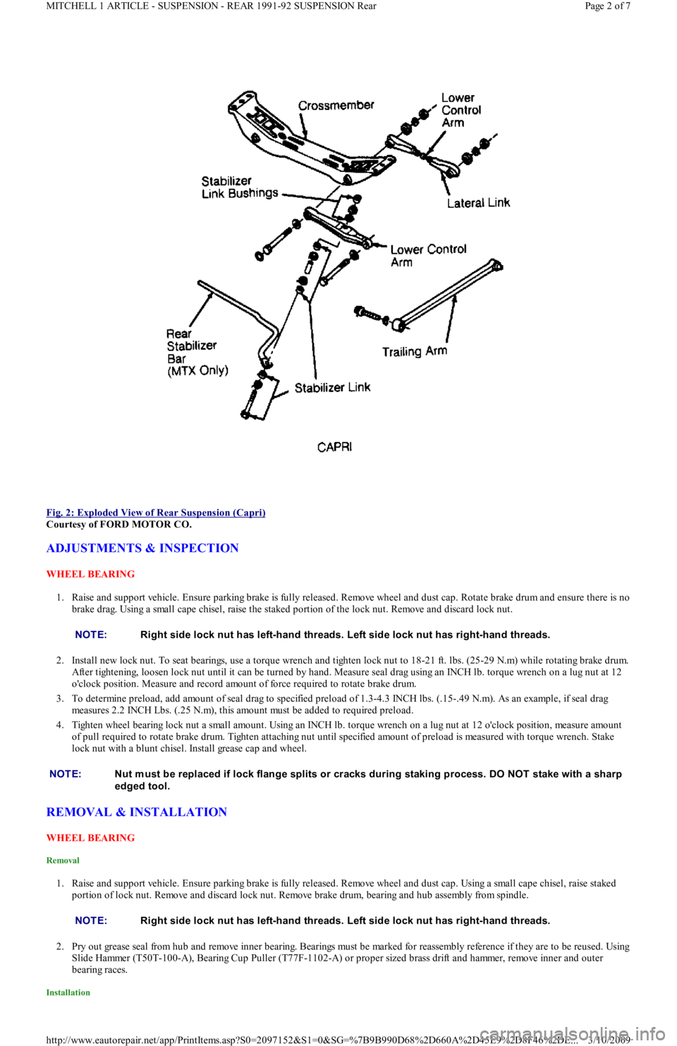
Fig. 2: Exploded View of Rear Suspension (Capri)
Courtesy of FORD MOTOR CO.
ADJUSTMENTS & INSPECTION
WHEEL BEARING
1. Raise and support vehicle. Ensure parking brake is fully released. Remove wheel and dust cap. Rotate brake drum and ensure there is no
brake drag. Using a small cape chisel, raise the staked portion of the lock nut. Remove and discard lock nut.
2. Install new lock nut. To seat bearings, use a torque wrench and tighten lock nut to 18-21 ft. lbs. (25-29 N.m) while rotating brake drum.
After tightening, loosen lock nut until it can be turned by hand. Measure seal drag using an INCH lb. torque wrench on a lug nut at 12
o'clock position. Measure and record amount of force required to rotate brake drum.
3. To determine preload, add amount of seal drag to specified preload of 1.3-4.3 INCH lbs. (.15-.49 N.m). As an example, if seal drag
measures 2.2 INCH Lbs. (.25 N.m), this amount must be added to required preload.
4. Tighten wheel bearing lock nut a small amount. Using an INCH lb. torque wrench on a lug nut at 12 o'clock position, measure amo u n t
of pull required to rotate brake drum. Tighten attaching nut until specified amount of preload is measured with torque wrench. Stake
lock nut with a blunt chisel. Install grease cap and wheel.
REMOVAL & INSTALLATION
WHEEL BEARING
Removal
1. Raise and support vehicle. Ensure parking brake is fully released. Remove wheel and dust cap. Using a small cape chisel, raise staked
portion of lock nut. Remove and discard lock nut. Remove brake drum, bearing and hub assembly from spindle.
2. Pry out grease seal from hub and remove inner bearing. Bearings must be marked for reassembly reference if they are to be reused. Using
Slide Hammer (T50T-100-A), Bearing Cup Puller (T77F-1102-A) or proper sized brass drift and hammer, remove inner and outer
bearing races.
Installation
NOTE:Right side lock nut has left-hand threads. Left side lock nut has right-hand threads.
NOTE:Nut m ust be replaced if lock flange splits or cracks during staking process. DO NOT stake with a sharp
edged tool.
NOTE:Right side lock nut has left-hand threads. Left side lock nut has right-hand threads.
Page 2 of 7 MITCHELL 1 ARTICLE - SUSPENSION - REAR 1991-92 SUSPENSION Rear
3/10/2009 http://www.eautorepair.net/app/PrintItems.asp?S0=2097152&S1=0&SG=%7B9B990D68%2D660A%2D45E9%2D8F46%2DE
...
Page 398 of 454
1. Using Installer (T77F-1217-A), Driver Handle (T80T-4000-W) or proper sized brass drift and hammer, install inner and outer bearing
races. Pack bearings and hub area with Lubricant (C1AZ-1959D-B, C, D or E).
2. Position inner bearing in bearing hub. Lubricate grease seal lips and install seal. Ensure bearings and hub have sufficient lubricant. Place
brake drum bearings and hub assembly on spindle. To prevent damage to grease seal and spindle threads, ensure hub is correctly
centered on spindle.
3. Install outer bearing, washer and new lock nut. Stake lock nut with a blunt chisel. Adjust bearing preload. See ADJUSTMENTS &
INSPECTION.
SPINDLE
Removal & Installation (Capri)
Remove wheel, caliper and brake rotor. Loosen spindle-to-strut attaching bolts. Loosen outer rear control arm common bolt and nut. Remove
spindle-to-strut mount bolts and common control arm bolt. Remove spindle from strut. To install, reverse removal procedure.
Removal & Installation (Festiva)
Remove brake drum assembly. Remove 4 spindle attaching nuts located on inboard side of torsion beam. Support backing plate with wire and
remove spindle. To install, reverse removal procedure. Tighten spindle attaching nuts to 32-45 ft. lbs. (43-61 N.m).
STRUTS
Removal & Installation (Capri)
1. Remove wheel, caliper and brake rotor. Remove trailing arm bolt and spindle-to-strut attaching bolts. Put index mark on strut rubber
mounting bracket. Remove upper strut attaching nuts from inside vehicle. Remove strut.
2. Compress strut coil spring with Spring Compressor (T18P-5310-A) or similar. Remove strut nut while spring is compressed. Remove
rubber mounting bracket, upper and lower spring seats. Slowly release coil spring and remove spring compressor. Remove coil spring,
dust boot and rebound bumpers. To install, reverse removal procedure.
Removal (Festiva)
1. Raise and support vehicle. Remove rear wheels. Using Spring Compressor (T81P-5310-A), compress spring to unload strut. Remove rear
quarter trim panel from cargo compartment.
2. Remove jam nut and flanged nut from strut rod. Remove bushing washer and upper bushing. Remove strut lower end mounting bolt
from wheel support arm. Remove strut and separate it from spring and seat insulator. Remove lower bushing and jounce bumper seat
from strut rod. Slide jounce bumper and shield off strut. See Fig. 3
. NOTE:Nut m ust be replaced if lock flange splits or cracks during staking process. DO NOT stake with a sharp-
edged tool.
Page 3 of 7 MITCHELL 1 ARTICLE - SUSPENSION - REAR 1991-92 SUSPENSION Rear
3/10/2009 http://www.eautorepair.net/app/PrintItems.asp?S0=2097152&S1=0&SG=%7B9B990D68%2D660A%2D45E9%2D8F46%2DE
...
Page 399 of 454
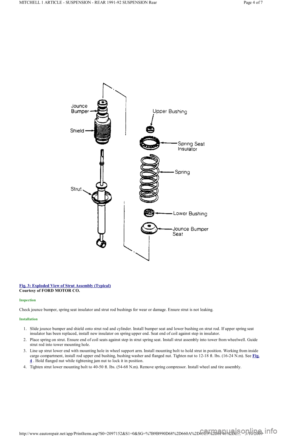
Fig. 3: Exploded View of Strut Assembly (Typical)
Courtesy of FORD MOTOR CO.
Inspection
Check jounce bumper, spring seat insulator and strut rod bushings for wear or damage. Ensure strut is not leaking.
Installation
1. Slide jounce bumper and shield onto strut rod and cylinder. Install bumper seat and lower bushing on strut rod. If upper spring seat
insulator has been replaced, install new insulator on spring upper end. Seat end of coil against step in insulator.
2. Place spring on strut. Ensure end of coil seats against step in strut spring seat. Install strut assembly into tower from wheelwell. Guide
strut rod into tower mounting hole.
3. Line up strut lower end with mounting hole in wheel support arm. Install mounting bolt to hold strut in position. Working from in sid e
cargo compartment, install rod upper end bushing, bushing washer and flanged nut. Tighten nut to 12-18 ft. lbs. (16-24 N.m). See Fig.
4 . Hold flanged nut while tightening jam nut to lock it in position.
4. Tighten strut lower mounting bolt to 40-50 ft. lbs. (54-68 N.m). Remove spring compressor. Install wheel and tire assembly.
Page 4 of 7 MITCHELL 1 ARTICLE - SUSPENSION - REAR 1991-92 SUSPENSION Rear
3/10/2009 http://www.eautorepair.net/app/PrintItems.asp?S0=2097152&S1=0&SG=%7B9B990D68%2D660A%2D45E9%2D8F46%2DE
...
Page 400 of 454
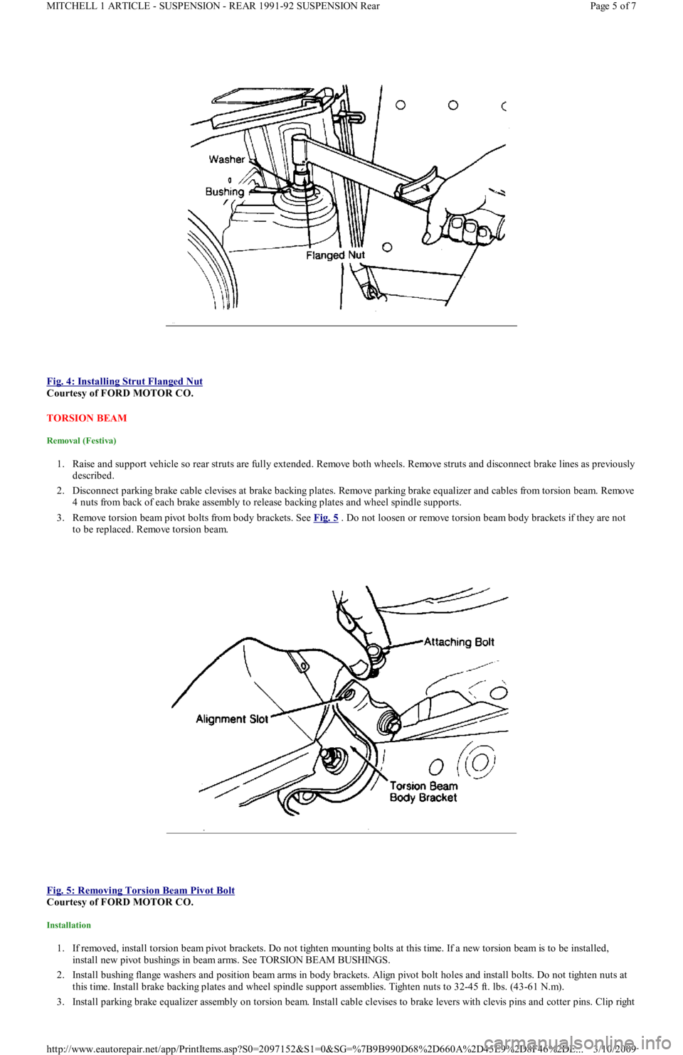
Fig. 4: Installing Strut Flanged Nut
Courtesy of FORD MOTOR CO.
TORSION BEAM
Removal (Festiva)
1. Raise and support vehicle so rear struts are fully extended. Remove both wheels. Remove struts and disconnect brake lines as previously
described.
2. Disconnect parking brake cable clevises at brake backing plates. Remove parking brake equalizer and cables from torsion beam. Remove
4 nuts from back of each brake assembly to release backing plates and wheel spindle supports.
3. Remove torsion beam pivot bolts from body brackets. See Fig. 5
. Do not loosen or remove torsion beam body brackets if they are not
to be replaced. Remove torsion beam.
Fig. 5: Removing Torsion Beam Pivot Bolt
Courtesy of FORD MOTOR CO.
Installation
1. If removed, install torsion beam pivot brackets. Do not tighten mounting bolts at this time. If a new torsion beam is to be installed,
install new pivot bushings in beam arms. See TORSION BEAM BUSHINGS.
2. Install bushing flange washers and position beam arms in body brackets. Align pivot bolt holes and install bolts. Do not tighten nuts at
this time. Install brake backing plates and wheel spindle support assemblies. Tighten nuts to 32-45 ft. lbs. (43-61 N.m).
3. Install parking brake equalizer assembly on torsion beam. Install cable clevises to brake levers with clevis pins and cotter pins. Clip right
Page 5 of 7 MITCHELL 1 ARTICLE - SUSPENSION - REAR 1991-92 SUSPENSION Rear
3/10/2009 http://www.eautorepair.net/app/PrintItems.asp?S0=2097152&S1=0&SG=%7B9B990D68%2D660A%2D45E9%2D8F46%2DE
...
Page 401 of 454
and left brake lines in place. Install rear suspension struts and wheels. Block wheels and lower vehicle to load suspension to normal ride
height. Tighten torsion beam pivot bolts at body brackets to 69-87 ft. lbs. (93-118 N.m).
4. Check rear suspension alignment. Place an alignment mark at the center of the underbody, at a point of equal distance from the right and
left body bracket inboard mounting bolts. From this alignment mark, measure distance to centers of right and left strut lower mounting
bolts.
5. Both measurements must be within .20" (5 mm) of being the same. If not, shift torsion beam body brackets from side-to-side to center
suspension. Once centered, tighten upper body bracket mounting bolts to 40-50 ft. lbs. (54-68 N.m) and lower bolt to 69-87 ft. lbs. (93-
118 N.m). Bleed brakes.
TORSION BEAM BUSHINGS
Removal
1. Raise and support vehicle to fully extended rear struts. Remove wheels. Remove retaining clip at right brake line routing bracket and
disconnect brake line. Remove clip from left brake line and disconnect at body crossmember.
2. Remove torsion beam pivot bolt bolts and nuts at right and left body brackets. Swing torsion beam trailing arm downward to clear body
brackets.
3. Using piece of wood, block beam in disengaged position. Using Bushing Remover/Replacer (D80L-1002-L), remove bushings from
inboard side of torsion beam arm. See Fig. 6
.
Fig. 6: Removing Torsion Beam Bushing
Courtesy of FORD MOTOR CO.
Installation
1. Place bushings on outboard sides of torsion beam arms with marks "F" and "R" aligned parallel to arm axis. To ease installation,
lubricate bushings with soapy water. Press in bushings using bushing remover/installer.
2. Remove wood block holding torsion beam out of body pivot brackets. Place bushing flange washers on outboard faces of bushings.
Raise torsion beam arms into brackets until pivot bolt holes align.
3. Install pivot bolts through brackets from inboard side but do not tighten nuts at this time. Connect brake lines at routing brackets.
Reinstall brake line retaining clips. Reinstall wheels. Lower vehicle and block wheels. Jounce vehicle until suspension is fully loaded in
its normal riding position. Tighten torsion beam pivot bolt nuts to 69-87 ft. lbs. (93-118 N.m). Bleed brakes.
TORQUE SPECIFICATIONS
TORQUE SPECIFICATIONS
NOTE:Bushings have "F" (front) and "R" (rear) stam ped on bushing face. Ensure these m arks are right side
up when "F" is toward front of vehicle.
ApplicationFt. Lbs. (N.m)
Capri
Control Arm Bolt-To-Spindle45-55 (61-75)
Inner Control Arm Bolts69-86 (93-117)
Rear Hub Lock Nut18-21 (25-29)
Rear Stabilizer Bracket32-39 (43-55)
Spindle-To-Strut Bolts69-86 (93-117)
Strut Rod Upper Flanged Nut40-50 (54-68)
Strut-To-Strut Tower17-22 (23-29)
Wheel Bearing Lock Nut18-21 (25-29)
Wheel Lug Nuts67-88 (90-120)
Festiva
Brake Backing Plate Spindle Support Bolts32-45 (43-61)
Lower Body Bracket Mounting Bolts69-87 (93-118)
Page 6 of 7 MITCHELL 1 ARTICLE - SUSPENSION - REAR 1991-92 SUSPENSION Rear
3/10/2009 http://www.eautorepair.net/app/PrintItems.asp?S0=2097152&S1=0&SG=%7B9B990D68%2D660A%2D45E9%2D8F46%2DE
...