Page 986 of 1640
Engine Removal/Installation
Make sure jacks and safety stands are placed proper-ly and hoist brackets are attached to the correct
positions on the engine (see section 1).
Make sure the car will not roll off stands and fall
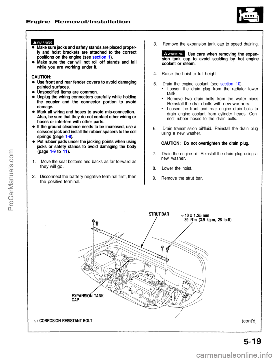
while you are working under it. 3. Remove the expansion tank cap to speed draining.
Use care when removing the expan-
sion tank cap to avoid scalding by hot engine
coolant or steam.
4. Raise the hoist to full height.
5. Drain the engine coolant (see section 10).
STRUT BAR
10 x
1.25
mm
39 N.m (3.9 kg-m, 28 Ib-ft)
EXPANSION TANK
CAP
: CORROSION RESISTANT BOLT
(cont'dj
1. Move the seat bottoms and backs as far forward as
they will go.
2. Disconnect the battery negative terminal first, then
the positive terminal.
Loosen the drain plug from the radiator lower
tank.
Remove two drain bolts from the water pipes
Reinstall the drain bolts with new washers.
Loosen the front and rear engine drain bolts to
drain engine coolant from cylinder heads. Con-
nect rubber hoses to the drain bolts.
6. Drain transmission oil/fluid. Reinstall the drain plug using a new washer.
CAUTION: Do not overtighten the drain plug.
7. Drain the engine oil. Reinstall the drain plug using a new washer.
8. Lower the hoist.
9. Remove the strut bar.
CAUTION:
Use front and rear fender covers to avoid damaging
painted surfaces.
Unspecified items are common.Unplug the wiring connectors carefully while holding
the coupler and the connector portion to avoid damage.
Mark all wiring and hoses to avoid mis-connection.
Also, be sure that they do not contact other wiring or hoses or interfere with other parts.
If the ground clearance needs to be increased, use a
scissors jack and install the rubber spacers to the coil
springs (page 1-8).
Put rubber pads under the jacking points when using
jacks or safety stands to avoid damaging the body (page 1-9 to 11).ProCarManuals.com
Page 1224 of 1640
Fluid Level
Checking/Changing
Checking
NOTE: Check the fluid level with the engine at nor-
mal operating temperature (the cooling fan comes
on).
1. Park the car on level ground. Turn off the engine.
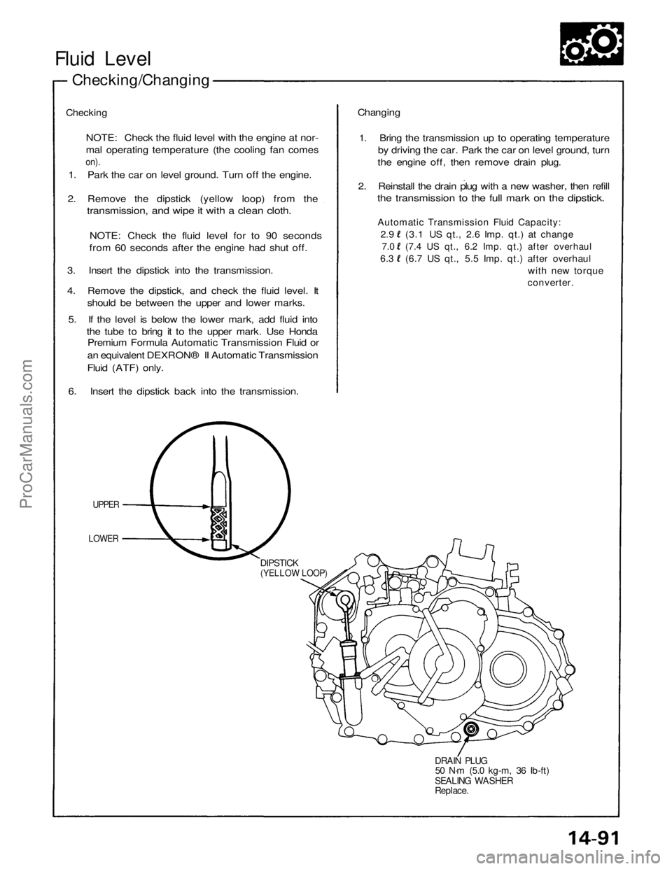
2. Remove the dipstick (yellow loop) from the
transmission, and wipe it with a clean cloth.
NOTE: Check the fluid level for to 90 seconds
from 60 seconds after the engine had shut off.
3. Insert the dipstick into the transmission.
4. Remove the dipstick, and check the fluid level. It
should be between the upper and lower marks.
5. If the level is below the lower mark, add fluid into
the tube to bring it to the upper mark. Use Honda
Premium Formula Automatic Transmission Fluid or
an equivalent DEXRON® II Automatic Transmission
Fluid (ATF) only.
6. Insert the dipstick back into the transmission.
UPPER
LOWER
DIPSTICK
(YELLOW LOOP)
DRAIN PLUG
50 N·m (5.0 kg-m, 36 Ib-ft)
SEALING WASHER
Replace.
Changing
1. Bring the transmission up to operating temperature
by driving the car. Park the car on level ground, turn
the engine off, then remove drain plug.
2. Reinstall the drain plug with a new washer, then refill
the transmission to the full mark on the dipstick.
Automatic Transmission Fluid Capacity:
2.9 (3.1 US qt., 2.6 Imp. qt.) at change
7.0 (7.4 US qt., 6.2 Imp. qt.) after overhaul
6.3 (6.7 US qt., 5.5 Imp. qt.) after overhaul
with new torque
converter.ProCarManuals.com
Page 1225 of 1640
Pressure Testing
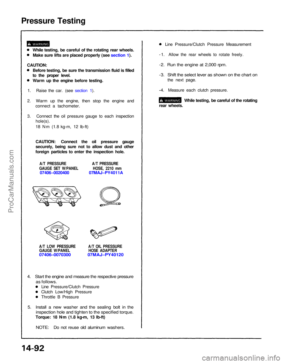
A/T LOW PRESSURE A/T OIL PRESSUREGAUGE W/PANEL HOSE ADAPTER
07406–0070300 07MAJ–PY40120
1. Allow the rear wheels to rotate freely.
2. Run the engine at 2,000 rpm.
3. Shift the select lever as shown on the chart on
the next page.
4. Measure each clutch pressure.
While testing, be careful of the rotating
rear wheels.
4. Start the engine and measure the respective pressure
as follows.
Line Pressure/Clutch Pressure
Clutch Low/High Pressure
Throttle B Pressure
5. Install a new washer and the sealing bolt in the
inspection hole and tighten to the specified torque.
Torque: 18 N .
m (1.8 kg-m, 13 Ib-ft)
NOTE: Do not reuse old aluminum washers.
While testing, be careful of the rotating rear wheels.
Make sure lifts are placed properly (see section 1).
CAUTION: Before testing, be sure the transmission fluid is filled
to the proper level.
Warm up the engine before testing.
1. Raise the car. (see section 1).
2. Warm up the engine, then stop the engine and connect a tachometer.
3. Connect the oil pressure gauge to each inspection
hole(s).
18 N .
m (1.8 kg-m, 12 Ib-ft)
CAUTION: Connect the oil pressure gauge
securely, being sure not to allow dust and other
foreign particles to enter the inspection hole.
A/T PRESSURE A/T PRESSURE
GAUGE SET W/PANEL HOSE, 2210 mm
07406–0020400 07MAJ–PY4011A Line Pressure/Clutch Pressure MeasurementProCarManuals.com
Page 1229 of 1640
Transmission
Removal
Make sure lifts are placed properly, and
hoist brackets are attached to correct position (see sec-
tion 1).
CAUTION: Use fender covers to avoid damaging painted
surfaces.
1. Check and record the rear camber. (see section 18.)
2. Disconnect the battery negative (-) first, and positive (+) cable from the battery.
3. Drain automatic transmission fluid (ATF). Reinstall the drain plug with a new washer.
NOTE: Removing the ATF level gauge will allow the
ATF to drain more rapidly. 4. Remove the strut bar.
5. Remove the air cleaner housing.
6. Remove the connectors from the control box and remove the control box (see section 11).
CAUTION: Do not remove the vacuum tubes from
the control box.
7. Remove the wire harness holder, disconnect the vehicle speed sensor (VSS) wire connectors,
solenoid valve wire connectors, starter motor
cables and transmission ground cable.
8. Remove the ATF cooler as it is connected by the
hoses.
CAUTION: Do not remove the hoses from the ATF
cooler.
9. Remove the starter motor mounting bolts, then remove the starter motor.
10. Remove the transmission housing bolts and the transmission mounting bolts.
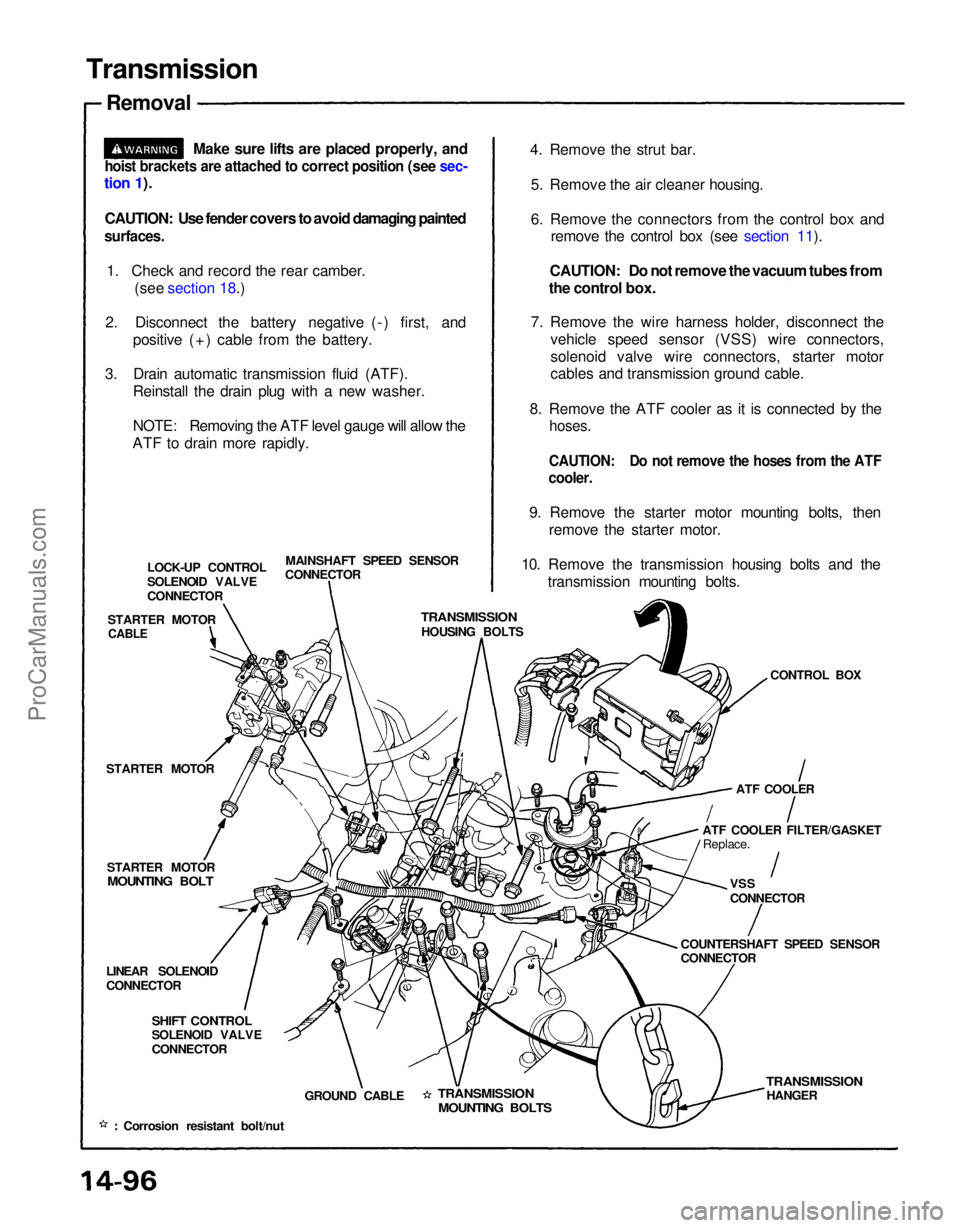
MAINSHAFT SPEED SENSOR
CONNECTOR
LOCK-UP CONTROL
SOLENOID VALVE
CONNECTOR
STARTER MOTOR
TRANSMISSION
HOUSING BOLTS
CONTROL BOX
STARTER MOTOR
STARTER MOTOR
MOUNTING BOLT
ATF COOLER
ATF COOLER FILTER/GASKET Replace.
VSS
CONNECTOR
COUNTERSHAFT SPEED SENSOR
CONNECTOR
LINEAR SOLENOID
CONNECTOR
SHIFT CONTROL
SOLENOID VALVE
CONNECTOR
GROUND CABLE
TRANSMISSION
MOUNTING BOLTS
TRANSMISSION
HANGER
Corrosion resistant bolt/nut
CABLEProCarManuals.com
Page 1357 of 1640
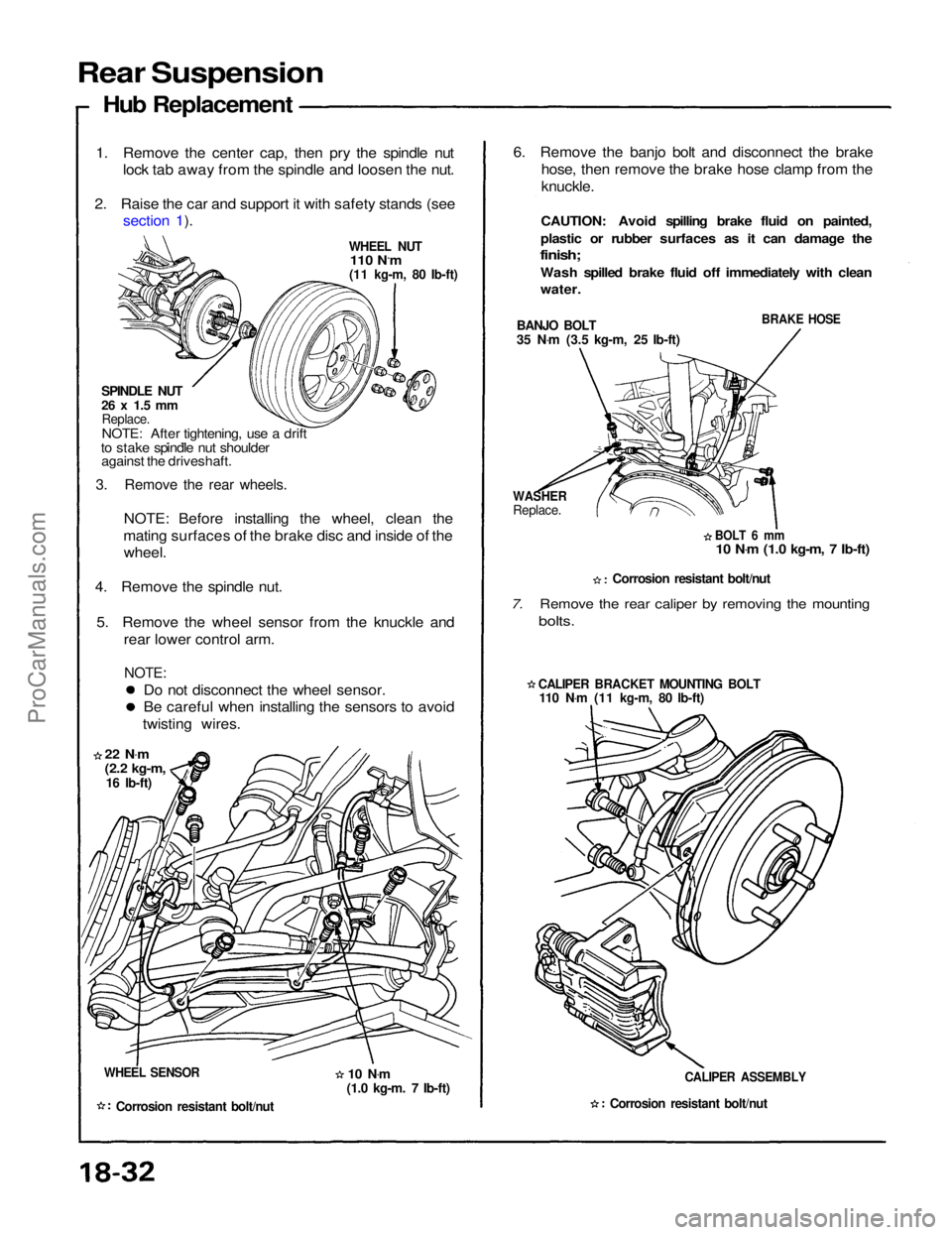
Rear Suspension
Hub Replacement
1. Remove the center cap, then pry the spindle nut
lock tab away from the spindle and loosen the nut.
2. Raise the car and support it with safety stands (see section 1).
WHEEL NUT
110 N.m
(11 kg-m, 80 Ib-ft)
SPINDLE NUT
26 x 1.5 mm
Replace.
NOTE: After tightening, use a drift
to stake spindle nut shoulder against the driveshaft.
3. Remove the rear wheels.
NOTE: Before installing the wheel, clean the
mating surfaces of the brake disc and inside of the wheel.
4. Remove the spindle nut.
5. Remove the wheel sensor from the knuckle and rear lower control arm.
NOTE:
Do not disconnect the wheel sensor.
Be careful when installing the sensors to avoid
twisting wires.
22 N .
m
(2.2 kg-m,
16 Ib-ft)
WHEEL SENSOR
Corrosion resistant bolt/nut
6. Remove the banjo bolt and disconnect the brake
hose, then remove the brake hose clamp from the
knuckle.
CAUTION: Avoid spilling brake fluid on painted,
plastic or rubber surfaces as it can damage the
finish;
Wash spilled brake fluid off immediately with clean
water.
BANJO BOLT
35 N .
m (3.5 kg-m, 25 Ib-ft)
BRAKE HOSE
WASHER
Replace.
BOLT 6 mm
10 N .
m (1.0 kg-m, 7 Ib-ft)
Corrosion resistant bolt/nut
7. Remove the rear caliper by removing the mounting
bolts.
CALIPER BRACKET MOUNTING BOLT
110 N .
m (11 kg-m, 80 Ib-ft)
CALIPER ASSEMBLY
Corrosion resistant bolt/nut
10 N
.
m
(1.0 kg-m. 7 Ib-ft)ProCarManuals.com