1990 VOLKSWAGEN TRANSPORTER engine overheat
[x] Cancel search: engine overheatPage 31 of 165
Downloaded from www.Manualslib.com manuals search engine
CONTROLS
AND
EQUIPMENT
Brake
booster
The brake booster works
only
when
the engine is running.
WARNING
When the vehicle is moving while the engine is not running, more force on
the brake pedal is required to bring the
vehicle to
a
stop. Conditions affecting braking
efficiency
Moisture or road salt
WARNING
•
Under
certain
climatic
and
operating
conditions such as passing
through
water, driving in
heavy
rain or after
washing the vehicle the effectiveness of the brakes can be reduced. In
winter
ice
can accumulate on the brake pads,
linings, discs and drums. Cautiously
apply brakes for a test. Brakes will dry,
ice
coatings will be cleaned off after a
few cautious brake applications.
• Driving for an extended period of
time
on salt covered roads
without
using
your
brakes can also affect brak
ing
efficiency. The accumulated salt
coating
must be cleaned off the brake
discs
and brake pads be
a
few cautious brake applications.
• Do not "ride the brakes" by resting
your
foot
on the pedal
when
not in
tending to brake.
This
may cause the brakes to overheat, premature wear
and increased stopping distance. • Before descending
a
steep grade, re
duce speed and shift transmission into
a
lower
gear or
lower
driving position to control speed. Do not
ride
the
brakes or hold the pedal
down
too long, or too
often.
This
could cause the brakes to get hot
and
diminish
braking efficiency.
New brake pads or linings • New brake pads and linings do not have
optimum friction properties and must be
"broken in" during the initial 100 to 150
miles
(150 to 200 kilometers) of normal
city driving. You can compensate for this by applying more pressure on the brake
pedal.
This
also applies later
when
new
pads or linings are installed.
Brake
fluid level • If the brake fluid level is too low,
malfunctions or
even
a failure in the brake
system could result.
Therefore,
it is important to check
your
brake fluid level
regularly. See page 108 for more details.
Low brake fluid is indicated by the brake
warning light (see page 43).
www.westfaliaT3.info - a useful website for owners and enthusiasts of VW Westfalia T25 / T3 Campervans
Page 32 of 165
Downloaded from www.Manualslib.com manuals search engine
CONTROLS AND
EQUIPMENT
=ailure
of one
brake
circuit
I the brake pedal travel should suddenly
icrease,
one of the brake circuits may
_ave
failed. Should this happen, you will
m able to bring your vehicle safely to a
s:op,
however, you will have to push hard
er on the brake pedal and it will take a onger distance to stop the vehicle.
Con
tact your Volkswagen dealership for as
sistance.
Brake
wear
~he brakes on our automobiles are still subject to wear depending largely on operating conditions and driving habits. On ve
hicles
which are driven mostly in stop-and-
50 city
traffic
or which are driven hard, the
crake linings should be checked by your
Volkswagen
dealer more often than
specified
in the Maintenance brochure.
Front
spoiler
If you
install
a
front
spoiler on
your
vehi
cle, be
sure
the air
flow
to the
front
brakes
is not
obstructed,
otherwise
the
brake
system
could
overheat.
Parking
brake
lever
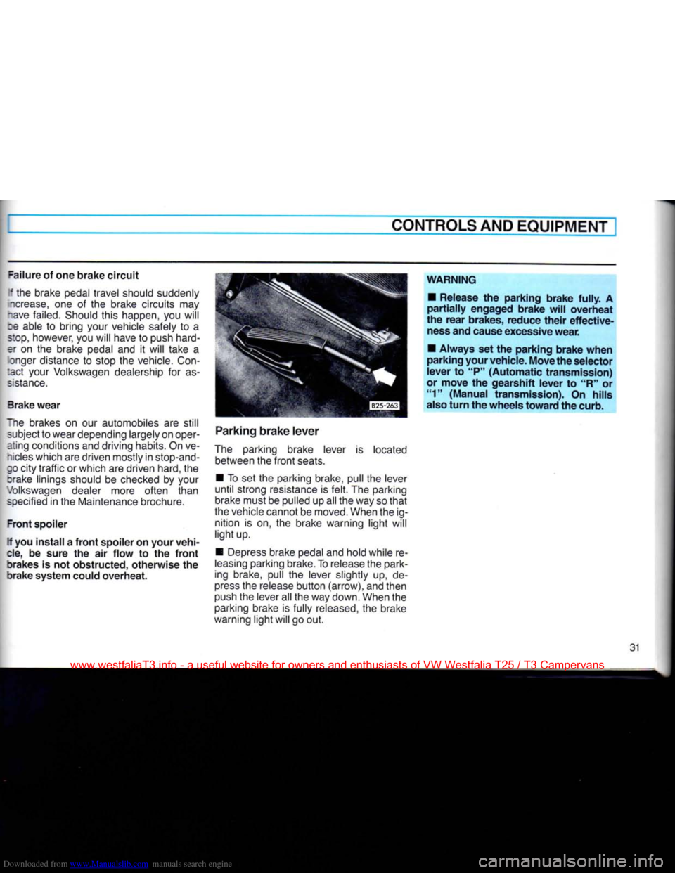
The parking brake lever is located between the
front
seats.
• To set the parking brake, pull the lever
until
strong resistance is
felt.
The parking
brake must be pulled up all the way so
that
the vehicle cannot be moved. When the ig nition is on, the brake warning
light
will
light
up.
• Depress brake pedal and hold while re
leasing
parking brake. To release the park
ing brake, pull the lever slightly up, de
press
the release
button
(arrow), and then
push the lever all the way down. When the parking brake is fully released, the brake
warning
light
will go out.
WARNING
•
Release
the
parking
brake
fully.
A
partially
engaged
brake
will
overheat
the
rear
brakes,
reduce
their
effective
ness and cause excessive
wear.
•
Always
set the
parking
brake
when
parking
your
vehicle.
Move
the
selector
lever
to "P"
(Automatic
transmission)
or
move
the
gearshift
lever
to "R" or "1"
(Manual
transmission).
On
hills
also
turn
the
wheels
toward
the curb.
31
www.westfaliaT3.info - a useful website for owners and enthusiasts of VW Westfalia T25 / T3 Campervans
Page 43 of 165
Downloaded from www.Manualslib.com manuals search engine
CONTROLS
AND
EQUIPMENT
WARNING continned •
The
engine compartment
of any
motor vehicle
is a
potentially hazard
ous
area.
Before you check anything in the engine compartment, stop
the
engine and
let it
cool down. Always
exercise extreme caution when work
ing
one the
engine. Heed
all of the
WARNINGS on page
97.
Reduce the risk
of
scalding from
hot
coolant by following these steps.
• If the coolant reservoir cap must be
removed, wait until
the
engine
has
cooled down.
• Protect face, hands
and
arms
by
covering
the cap
with
a
large, thick
rag
to
protect against escaping fluid
and
steam.
• Carefully and slowly
turn
cap
one
turn
to
allow excess pressure
to es
cape before completely removing
cap.
•
To
help avoid being burned,
do not
spill
antifreeze
or
coolant
on the ex
haust system
or hot
engine parts.
Under
some conditions, the ethylene
glycol
in
engine coolant
is
combusti
ble.
If a
visual check shows that coolant level
and V-belt
are
normal,
but the
warning light continues to
flash,
contact
your
near
est dealer
to
have
the
cause located
and
corrected.
For more details see "Cooling system"
on
page 104.
If the
coolant gauge needle nears
the
upper end
of
the scale and the engine ap
pears
to be
overheating,
turn
off the air
conditioner.
Do
not
install accessories
(fog
lights
or
in
sect screens,
for
example)
on top of the
front
bumper.
They
may
restrict engine
cooling.
5
-
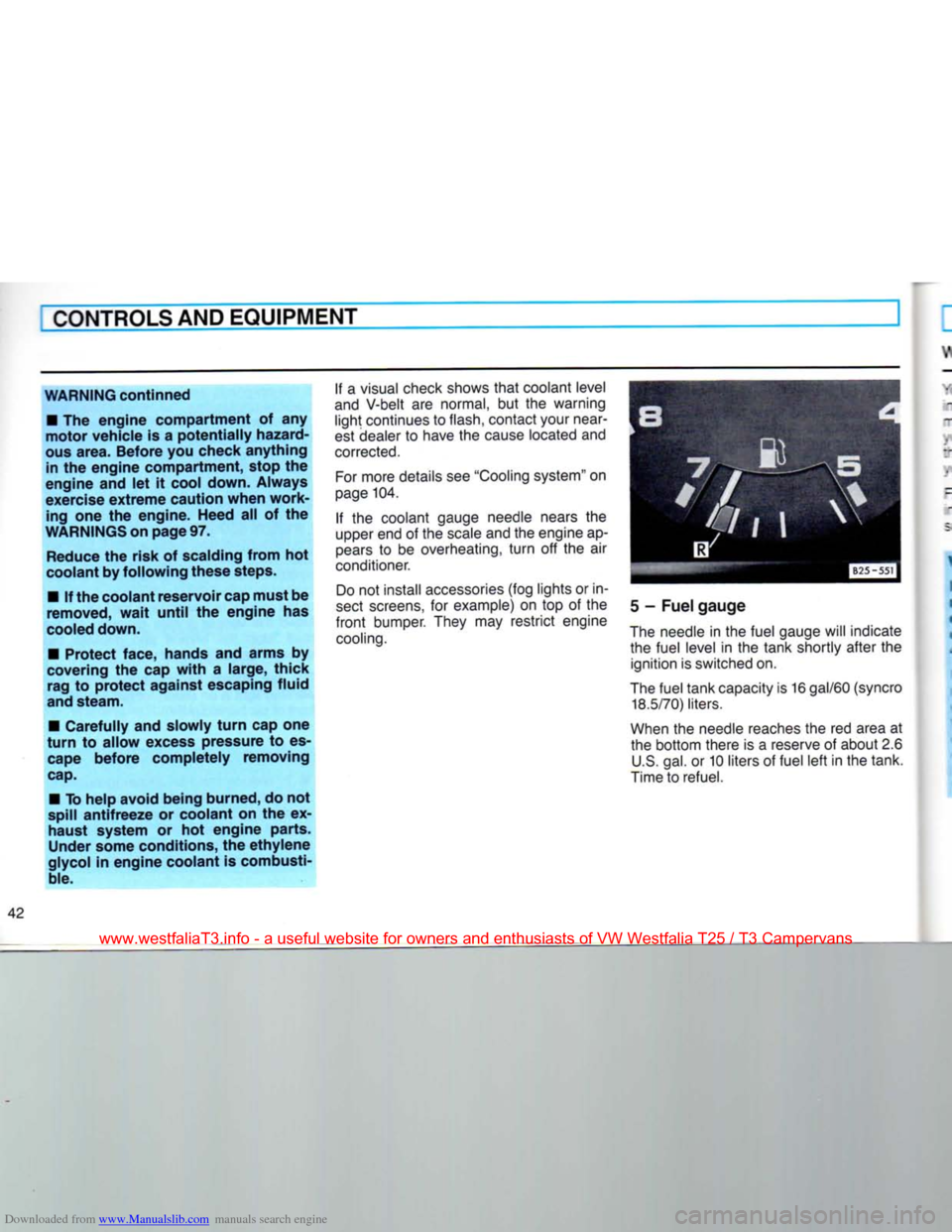
Fuel gauge
The needle
in
the fuel gauge will indicate the fuel level
in the
tank shortly after
the
ignition is switched on.
The fuel tank capacity is
16
gal/60
(syncro
18.5/70)
liters.
When
the
needle reaches the
red
area
at
the bottom there
is a
reserve
of
about 2.6 U.S. gal.
or
10 liters
of
fuel left in the tank.
Time to refuel.
www.westfaliaT3.info - a useful website for owners and enthusiasts of VW Westfalia T25 / T3 Campervans
Page 60 of 165
Downloaded from www.Manualslib.com manuals search engine
CONTROLS AND EQUIPMENT
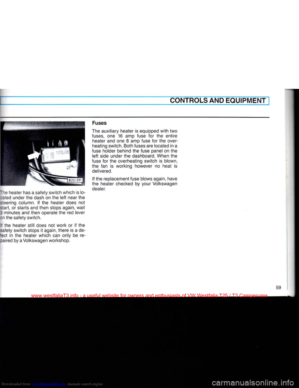
lie heater has a safety switch which is lo- :ated under the dash on the left near the
steering column. If the heater does not
start, or starts and then stops again, wait
3 minutes and then operate the red lever
on the safety switch.
[f the heater still does not work or if the
safety switch stops it again, there is a de-
:ect in the heater which can only be re- :aired by a Volkswagen workshop. Fuses
The auxiliary heater is equipped with two
fuses,
one 16 amp fuse for the entire heater and one 8 amp fuse for the over
heating switch. Both fuses are located in a
fuse holder behind the fuse panel on the left side under the dashboard. When the
fuse for the overheating switch is blown,
the fan is working however no heat is
delivered.
If the replacement fuse blows again, have
the heater checked by your Volkswagen dealer.
59
www.westfaliaT3.info - a useful website for owners and enthusiasts of VW Westfalia T25 / T3 Campervans
Page 99 of 165
Downloaded from www.Manualslib.com manuals search engine
VEHICLE CARE
CORROSION
PROTECTION
The transmission,
front
and rear axle
assembly
surfaces have been treated at
the factory
with
a wax based coating for protection against corrosion. However, we
recommend to have the and the underside
inspected twice a year for any damage to
the protective coating preferably before and after the winter
season.
Have
neces
sary
repairs done as soon as possible.
See
your dealer for correct procedures
and materials.
WARNING
Do not
apply
additional
undercoating
or
rustproofing
on or
near
the
exhaust
manifold,
exhaust
pipes,
catalytic
converter
or
heat
shields.
During
driv
ing, the substance used for
under-
coating
could
overheat
and cause a
fire.
Engine
Compartment
When washing the engine compartment, only use commercially available grease
cutting solvents made especially for this
purpose.
Carefully follow directions
print
ed
on the container by the manufacturer.
WARNING
Never
use gasoline,
Diesel
fuel
or sol
vents
which
could
damage
rubber
parts
or
painted
surfaces and could
cause a
fire.
Chassis
The lower body shell of your Volkswagen
is
thoroughly protected against corrosion. However, it is recommended to have the
underside inspected twice a year. Any de
tected damage to the undercoating, due to road hazards, should be repaired prompt
ly. Oil based protective sprays must not be
applied.
Only tar or wax based anticorro-
sion
protectors are compatible
with
the
factory applied undercoating. Before ap plication, road
dirt,
salt spray deposits and
oily substances must be removed.
Whenever
the lower body
shell,
axle, transmission or engines assemblies have been repaired, the lost anti-corrosion
coating of the affected surfaces should be
reapplied.
Your
Volkswagen dealer has the appro priate materials, the necessary equipment
and is familiar
with
the application proce
dure. Therefore, any additional corrosion protection work should be performed by a
Volkswagen
dealer.
Body
cavity sealing
All
body cavities which could be affecte: by corrosion have been given a thorouc"
protection at the factory.
This
sealing does not require any inspe:
tion
or additional treatments. If any wa should seep out of the cavity when tN
ambient temperature is high, it can M removed
with
a plastic scraper and -.
suitable solvent. Be sure to observe a
safety and environmental regulations.
94
www.westfaliaT3.info - a useful website for owners and enthusiasts of VW Westfalia T25 / T3 Campervans
Page 109 of 165
Downloaded from www.Manualslib.com manuals search engine
VEHICLE
CARE
COOLING
SYSTEM
The cooling system
is
sealed and gener ally requires little attention.
The cooling system has been filled at the factory with
a
permanent coolant which
does not need to be changed. The coolant
consists
of a
mixture
of
water
and the
manufacturer's coolant additive
G 11 —
antifreeze
on
glycol basis with anticorro-
sion additives (40% for USA
models;
50%
for Canadian models).
This
mixture
assures
the
necessary frost protection
and protects
the
entire cooling system
against corrosion and
scaling,
and raises
the boiling point of the coolant.
Do
not
reduce
the
concentration
of the
coolant
in the
summer
by
adding plain
water.
The coolant additive proportion
must
be at least
40%
but not more than
60%,
to
maintain the antifreeze protection
and the cooling efficiency. For year round driving, antifreeze is added
at the factory for temperatures down to:
-13°
F/-25°C(USA)
-40°
F/-40°
C
(Canada)
Only
use
quality phosphate-free
anti
freeze containing ethylene glycol. Such antifreeze
is
available at
your
Volkswagen
dealer.
WARNING Antifreeze is poisonous. Always store antifreeze in its original container and
well
out of the reach of children. If you drain
the
coolant,
it must
be
caught
and
safely stored. Drained coolant should normally not be reused. Always des-
pose
of used coolant observing all en
vironmental regulations.
Coolant losses
Coolant losses may indicate
a
leak in
the
cooling
system.
In
this
case,
the
cooling
system should
be
inspected immediately by
your
Volkswagen dealer.
It is not
suffi
cient merely to add coolant.
In a
sealed system, losses can only occur
if
the
boiling point
of the
coolant
is ex
ceeded as
a
result of overheating.
Overheating can occur
if:
•
the
flow
of air to the
radiator
is
obstructed
by
leaves, dust, insects
or by
additional
lights installed
in
front
of the
radiator grille;
•
the boiling point of the coolant has been
reduced
due to an
incorrect mixture
of
coolant and water;
•
the
radiator fan
is not
working
- see
"Radiator
fan",
or;
•
the vehicle is being driven up
a
long
hill
j
in
a
low gear with engine speed
very
high
and
at
very
high ambient temperature
-
see
"Radiator fan".
If
the cause for the overheating cannot
be
determined
and
corrected, contact
your
Volkswagen dealer immediately, other-
I
wise serious engine damage could result.
104
Always
heed
WARNING on page
97.
www.westfaliaT3.info - a useful website for owners and enthusiasts of VW Westfalia T25 / T3 Campervans
Page 134 of 165

Downloaded from www.Manualslib.com manuals search engine
DO-IT-YOURSELF-SERVICE
Fuse arrangement No. Component Amp. No. Component Amp.
From left to right: 1
Radiator fan 30 17 Windshield wiperengine 10
2 Brake lights 10
18 Brake warning light,
3 Interior lights, illuminated heated driver's seat,
Make-up mirror, clock,
ciga
cruise control system 10
rette lighter, radio 15 19 Turn signals 10
4 Emergency flasher system 15 20 Number plate light,
5 Vacant headlight washer
10
6 Vacant 21 Low beam left
10
7 Tail and side light left 10
22 Low beam right 10
8 Tail and side light right
10
9 High beam right 10
10 High beam left
10 Additional fuses
11 Windshield wipers and washer
15 (in separate holders)
12 Cruise control system
Air conditioner, power above the fuse box:
windows, auxiliary heater, Instrument lightning
10
electric outside mirrors, Overheating fuse for auxiliary heater
10
auxiliary heat exchanger, Main fuse for auxiliary heater
20
rear window wiper 20 Central locking 20
13 Fresh air fan
20 Automatic fuse for window lifter
20
14 Rear window heating, heated
rear view mirror, light for Color codes
15
16 lighting switch
Back-up lights
Double tone horn 20
10
15 10 Amp. fuses - red
15 Amp. fuses - blue
15
16 lighting switch
Back-up lights
Double tone horn 20
10
15 20 Amp. fuses - yellow
30 Amp. fuses - green
The number on the face of the fuse is the amperage rating.
www.westfaliaT3.info - a useful website for owners and enthusiasts of VW Westfalia T25 / T3 Campervans
Page 149 of 165
Downloaded from www.Manualslib.com manuals search engine
TECHNICAL
DESCRIPTION
EMISSION
CONTROL SYSTEM
In the
interest
of
clean
air Pollution of our environment has become
a
problem
that
is of increasing concern to
all of us. We urge you to
join
us in our ef
forts
for cleaner air in controlling the pollu
tants emitted from the automobile.
You
can make a significant contribution to
keeping our air clean by:
• Always using lead free gasoline.
• Not
letting
your vehicle idle
unnecessa
rily.
• Following the recommended preven
tive maintenance schedule contained in
the maintenance booklet.
• Not removing or altering the emission
control system.
• Taking the precautions described
below to prevent damage to the emission
control system in your vehicle.
Volkswagen
warrants the Emission
Con
trol
System in your new vehicle under the
terms and conditions set
forth
in the War ranty booklet.
Your
Volkswagen is equipped
with
such a
system,
which contains the following major components.
Catalytic
converter
The catalytic converter is an efficient
"clean-up"
device
built
into
the exhaust system of the vehicle. The catalytic conver
ter burns the undesirable pollutants in the exhaust gas before it is released
into
the
atmosphere.
The
exclusive
use of
unleaded
fuel
is cri
tically
important
for the
life
of the
cataly
tic
converter
and
proper
functioning
of
the
engine.
The
catalytic
converter
will
be
perma
nently
damaged
by
•
exceeding
the "max"
marking
when
adding
engine
oil (see
page
99)
• push or tow
starting
your
vehicle
•
misfiring
of the
engine
•
turning
off the
ignition
while
the
vehicle
is
moving
or
•
other
unusual
operating
conditions. Do not
continue
to
operate
your
vehicle
under
these
conditions, as
otherwise
fuel
can
reach
the
catalytic
converter.
This could
result
in
overheating
of the
converter,
requiring
its
replacement.
For
maintenance intervals refer to your
Maintenance booklet.
Oxygen
Sensor (OXS)
The oxygen sensor, installed in the exhaust manifold, continuously
senses
the oxygen content of the exhaust and
signals
the information to an electronic
control
unit.
Carbon
canister
The vehicle is equipped
with
a carbon canister to prevent fuel vapor from
esca
ping
into
the atmosphere.
The vapor is passed
into
the carbon canister, where it is retained when the
engine is turned off. When the engine is running, a valve allows air
into
the canister,
and the fuel vapor is passed to the engine
for combustion.
The system does not require any main
tenance.
144
www.westfaliaT3.info - a useful website for owners and enthusiasts of VW Westfalia T25 / T3 Campervans