1990 VOLKSWAGEN TRANSPORTER fuse
[x] Cancel search: fusePage 4 of 165

Downloaded from www.Manualslib.com manuals search engine
1
INSTRUMENT PANEL
Illustration instruments and controls
Warning and indicator light symbols
CONTROLS AND EQUIPMENT
Keys,
central locking system .... 7, 8
Doors 9
Rear lid 11
Windows, mirrors 12, 13 Safety belts, head restraints . . . .14,19
Seats 20 Luggage compartment, pedals . 28,29
Brakes, Transmission 29, 32 Differential lock 33
Automatic-transmission 35 Steering lock/ignition/starter switch . 38
Starting procedures 39 Instrument cluster 40
Warning/indicator lights 43 Switches 46 Emergency flasher 46
Light switch, turn signals .... 46,48
Cruise control 49
Windshield wipers 50 Ventilation/Heating 51
Air conditioning 54
Heater 57
Sliding roof 62
Roof-rack 68 VEHICLE OPERATION
Break-in period - and afterwards . . 69
Operate your vehicle safety 70
Operate your vehicle economically
and minimize pollution 72
Trailer towing 73 Driving with the all-wheel drive ... 75
VEHICLE CARE
Fuel tank, fuel supply 85,86
Vehicle care (exterior/interior) . . 90, 93 Maintenance, inspection intervals . . 95 Engine compartment lid,
engine compartment 97 Lubricants, engine oil 98,99
Engine oil filter 101
Transmission oil 102
Power steering 103
Cooling system 104 Brake fluid 108
Battery 109
Windshield washers/wipers . . . 112,113
Tires/wheels 114 Difficult operating conditions .... 120
Winter driving 121
Accessories 122
DO-IT-YOURSELF SERVICE
Jack and tools 123 Spare wheel 124
Changing a wheel 125 Fuses, bulbs 128, 130 Adjusting headlights
134
Installing,
replacing the radio . . . . 135
Emergency starting 136
Emergency towing 138
Lifting vehicle . . 140
TECHNICAL DESCRIPTION
Engine, transmission 142
Steering,
suspension, brakes,
body, chassis 143 Emission-control-system 144
TECHNICAL DATA
Engine, spark plugs .
V-belts capacities . . Dimensions
Weights
Vehicle identification 146
147
148
150 151
CONSUMER INFORMATION
Service manuals 152
GAS STATION INFORMATION
Location of servicing points 156
ALPHABETICAL INDEX 158
www.westfaliaT3.info - a useful website for owners and enthusiasts of VW Westfalia T25 / T3 Campervans
Page 6 of 165
Downloaded from www.Manualslib.com manuals search engine
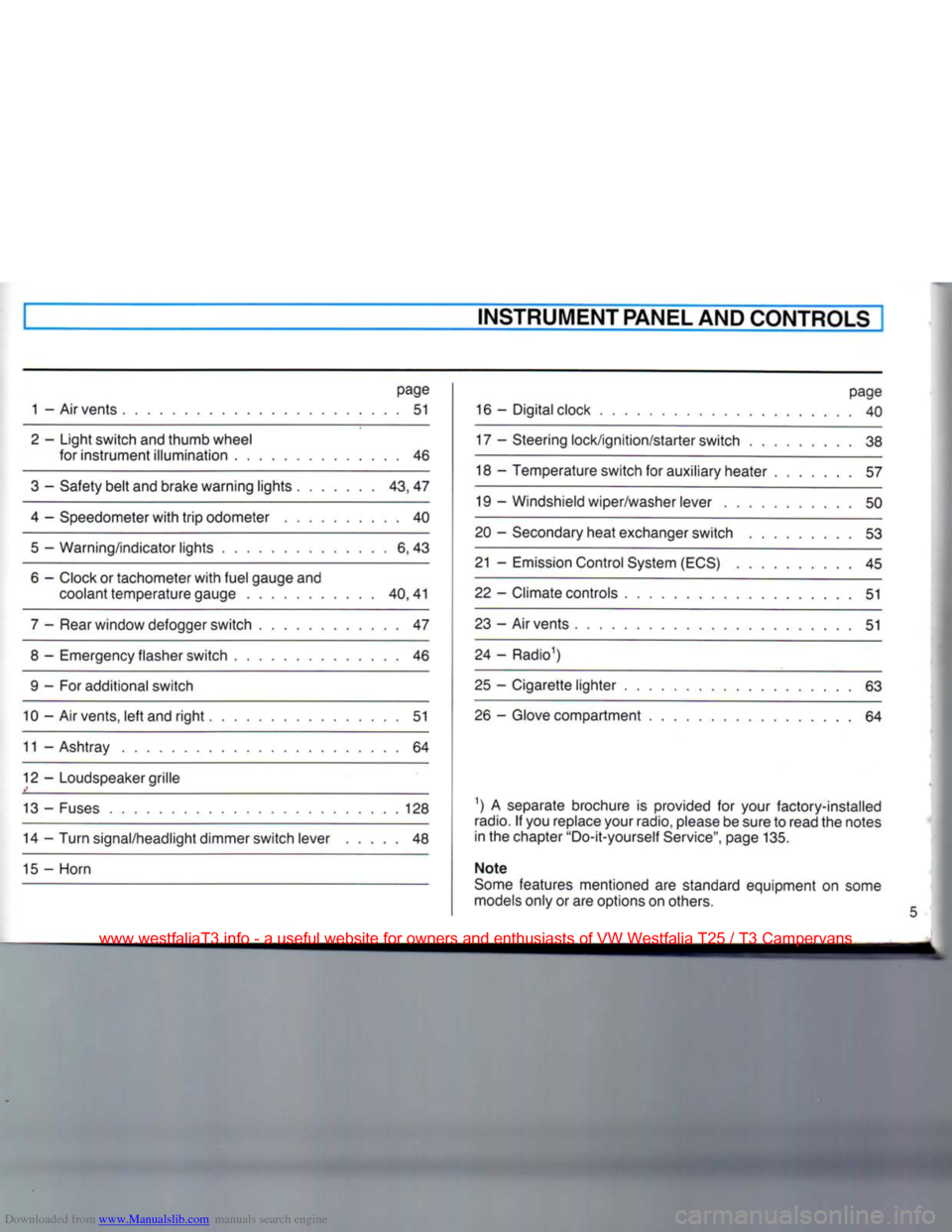
INSTRUMENT PANEL AND CONTROLS
page
1 - Air vents 51
2 - Light switch and thumb wheel for instrument illumination 46
3 - Safety belt and brake warning lights 43, 47
4 - Speedometer with trip odometer 40 5 — Warning/indicator lights 6, 43
6 - Clock or tachometer with fuel gauge and coolant temperature gauge 40,41
7 - Rear window defogger switch 47
8 - Emergency flasher switch 46 9 - For additional switch
10 - Air vents, left and right 51
11 - Ashtray 64
12 - Loudspeaker grille
13 - Fuses 128 14 - Turn signal/headlight dimmer switch lever 48
15 - Horn page
16 - Digital clock 40
17 - Steering lock/ignition/starter switch 38
18 - Temperature switch for auxiliary heater 57
19 - Windshield wiper/washer lever 50
20 - Secondary heat exchanger switch 53
21 - Emission Control System (ECS) 45
22 - Climate controls 51
23 - Air vents 51
24 - Radio1)
25 - Cigarette lighter 63 26 - Glove compartment 64
1) A separate brochure is provided for your factory-installed
radio.
If you replace your radio, please be sure to read the notes
in the chapter "Do-it-yourself Service", page 135.
Note
Some features mentioned are standard equipment on some
models only or are options on others.
www.westfaliaT3.info - a useful website for owners and enthusiasts of VW Westfalia T25 / T3 Campervans
Page 57 of 165
Downloaded from www.Manualslib.com manuals search engine
CONTROLS AND
EQUIPMENT
Malfunctions
if the
unit
does not
operate
• Outside temperatures may be below
41° For + 5°C.
• The air conditioner fuse may have blown. Turn the
unit
off and check fuse.
See
page 129 for use panel location.
General
hints
If
water
drips
under
the
vehicle
When outside temperature is high and the
air very humid, condensed water can drip
off the evaporator under the vehicle. This
is
normal and does not indicate a leak.
Payload
reduction
The weight of the air conditioner installed in your vehicle reduces the vehicle's load
carrying capacity. For weight information,
see
sticker on
left
doorjamb.
Maintenance
The condenser should be checked peri
odically for cleanliness. If clogged
with
dirt
or insects, the condenser should be
washed down
with
water.
After the winter months and before ex
tended summer
usage,
the air conditioner should be checked and, if necessary, ser
viced by your Volkswagen dealer.
www.westfaliaT3.info - a useful website for owners and enthusiasts of VW Westfalia T25 / T3 Campervans
Page 60 of 165
Downloaded from www.Manualslib.com manuals search engine
CONTROLS AND EQUIPMENT
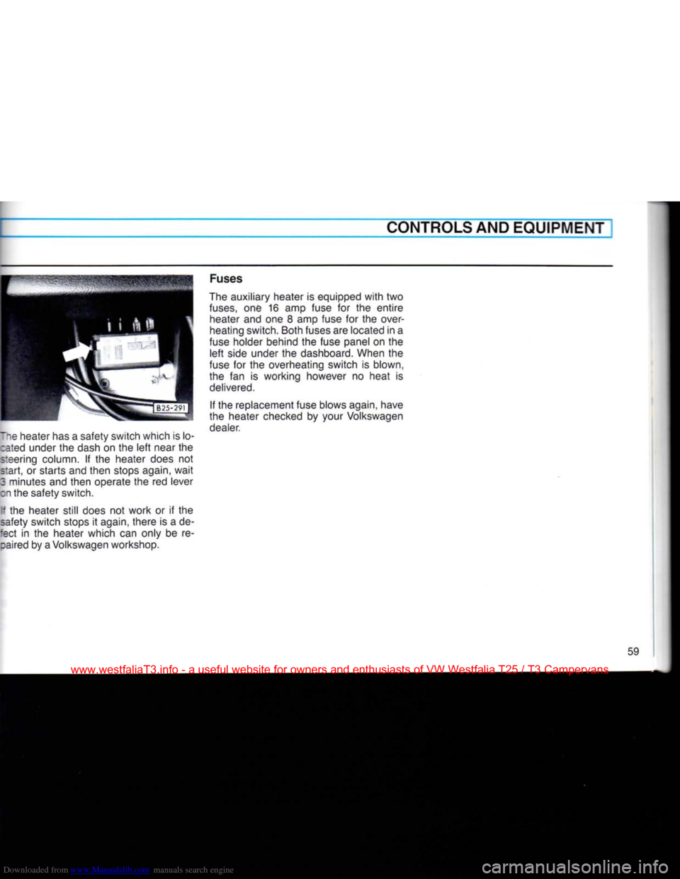
lie heater has a safety switch which is lo- :ated under the dash on the left near the
steering column. If the heater does not
start, or starts and then stops again, wait
3 minutes and then operate the red lever
on the safety switch.
[f the heater still does not work or if the
safety switch stops it again, there is a de-
:ect in the heater which can only be re- :aired by a Volkswagen workshop. Fuses
The auxiliary heater is equipped with two
fuses,
one 16 amp fuse for the entire heater and one 8 amp fuse for the over
heating switch. Both fuses are located in a
fuse holder behind the fuse panel on the left side under the dashboard. When the
fuse for the overheating switch is blown,
the fan is working however no heat is
delivered.
If the replacement fuse blows again, have
the heater checked by your Volkswagen dealer.
59
www.westfaliaT3.info - a useful website for owners and enthusiasts of VW Westfalia T25 / T3 Campervans
Page 62 of 165

Downloaded from www.Manualslib.com manuals search engine
CONTROLS AND EQUIPMENT
Setting
the
time
•
Press
and hold clock button E.
• Set clock
with
buttons A.
The
display lights up as long as button is
oressed.
When button is released the dis
play goes out or, if a time has been pre
selected,
the selected time lights up for 2
sees.
To
switch
heater
on or off • This is done by pressing button
F.
When
-eater is switched on the warning lamp G ghts up.
To
ensure
that
the heater starts the lever ;or the heat output must be pushed fully to
:ie
right.
This
closes
an electrical contact.
Preselecting
starting
time
for
heater
stationary operation, ignition off)
With buttons C two different switch-on
:imes
can be selected within 24 hours.
•
Press
and hold button. The appropriate
*:gure 1 or 2 appears in display. The ready- •or-action lamp lights up.
• Set required switch-on time
with
but
tons A. The display remains on for about 20 seconds after releasing button C.
To
ensure
that
the heater starts up at the
selected
time, the lever for the heat output must be pushed fully over to the
right.
In
addition to this the blower must be
switched to Stage 1. On account of the higher current consumption, a higher
stage
should only be selected in isolated
cases.
Switching
preselected
time
off • The preselected time can be switched
off by briefly pressing the appropriate but
ton C. The ready-for-action lamp and the figure in display then go out.
Fuses
The
fuses for the auxiliary heater are in an additional holder behind the main fuse
box.
Notes
• Every time the heater is switched off,
the warm air and combustion air blowers
continue running briefly to cool the heater
down quicker.
• To avoid draining the battery, do not run
the heater repeatedly when the engine is not running.
• When driving through mud and snow,
the exhaust pipe may tend to get blocked.
Have
a look at it occasionally to see
that
it
is
clear.
WARNING
Never
start
the
heater
or let the
engine
or the
heater
run in an enclosed,
unventilated
area.
Exhaust
fumes
from
the
engine
or the
heater
contain
carbon monoxide,
which
is colorless and odor
less.
Carbon monoxide,
however
is a
very
harmful
gas, and may be
fatal
if in haled.
Due to the
risk
of
fire
the
heater
must
not be used
when
vehicle
is
parked
on
dry grass, brush or leaves.
www.westfaliaT3.info - a useful website for owners and enthusiasts of VW Westfalia T25 / T3 Campervans
Page 108 of 165
Downloaded from www.Manualslib.com manuals search engine
VEHICLE
CARE
I
AIR CLEANER
A
dirty
filter
element reduces engine
out
put and increases fuel consumption and
can
cause premature engine wear.
Normally, it is not required to service the
air cleaner more often than recommended in the Maintenance booklet. If the vehicle
is
driven on very dusty roads, the air
cleaner
must be serviced more frequently,
even
daily. We recommend
that
you have
the air cleaner serviced by your
Volks
wagen dealer or a qualified workshop.
If
your
air
filter
must
be
changed more
frequently,
we
recommend
that
you have
your
Volkswagen dealer show
you the
procedure
before
you
attempt
doing
it
yourself.
The
paper
filter
element must never
be
cleaned
or
soaked
with
gasoline, clean
ing
solvents or oil. POWER STEERING*
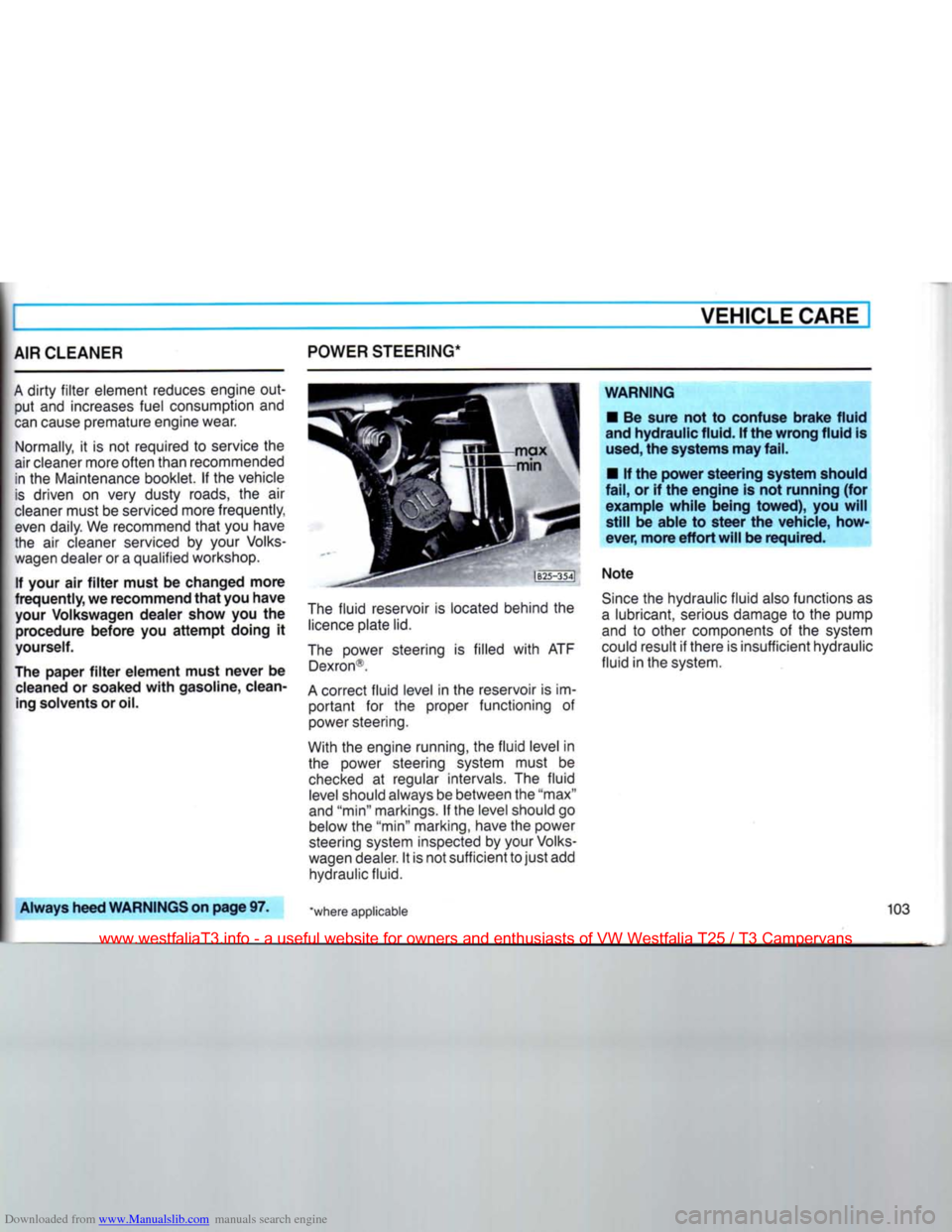
The
fluid
reservoir is located behind the
licence
plate lid.
The
power steering is filled
with
ATF Dexron®.
A
correct
fluid
level in the reservoir is im
portant
for the proper functioning of
power steering.
With the engine running, the
fluid
level in the power steering system must be
checked
at regular intervals. The
fluid
level
should always be between the "max"
and "min" markings. If the level should go below the "min" marking, have the power
steering system inspected by your
Volks
wagen dealer. It is not sufficient to
just
add hydraulic fluid.
WARNING
•
Be
sure
not to
confuse brake fluid
and
hydraulic fluid.
If
the wrong fluid
is
used,
the systems may fail.
•
If the
power steering system should
fail,
or if the
engine
is not
running
(for
example
while
being
towed),
you
will
still
be
able
to
steer
the
vehicle, how
ever, more
effort
will
be required.
Note
Since
the hydraulic
fluid
also functions as
a
lubricant, serious damage to the pump
and to other components of the system
could result if there is insufficient hydraulic
fluid
in the system.
Always
heed WARNINGS on page
97. "where applicable
www.westfaliaT3.info - a useful website for owners and enthusiasts of VW Westfalia T25 / T3 Campervans
Page 111 of 165
Downloaded from www.Manualslib.com manuals search engine
VEHICLE CARE
Adding
coolant
Turn
off the
engine
and allow it to cool
down.
WARNING
Reduce the
risk
of scalding
from
hot
coolant
by
following
these
steps.
• If the cap
from
the expansion
tank
must
be
removed
wait
until
the
engine
has cooled down. The cooling system
is
under
pressure.
•
Protect
face, hands and
arms
by
covering the cap
with
a
large,
thick
rag
to
protect
against
escaping
fluid
and steam.
•
Carefully
and
slowly
turn
cap one
turn
to
allow
excess pressure to es cape
before
completely
removing
cap.
Top
up coolant in refill tank. Only when
cooling
system was drained or a lot of
cool
ant needs to be added, also
fill
expansion
tank.
To
maintain the anti-corrosion properties of the coolant, the antifreeze concentra
tion should not be reduced, even during
the warm
season.
Increasing
the
antifreeze
in the
coolant
to
more
than
60% is not
only
unecono mical, it is also
detrimental
to
engine
cooling.
Only
use quality phosphate-free anti
freeze
containing ethylene glycol. Such antifreeze is available at your Volkswagen
dealer.
Antifreeze,
other
than
specified by Volks
wagen,
may cause corrosion of the cool ing system,
leading
to
engine
over
heating
and
damage.
Only
for topping-up coolant, a small amount of antifreeze containing ethylene
glycol
and phosphates may be
used,
if rec
ommended antifreeze is not available.
• After adding coolant, run the engine at
idle speed for a few seconds.
• Wait for the radiator fan to switch on
and
off again.
• Check coolant level. Add more coolant
if necessary.
Do
not overfill the system.
Excess
coolant will be forced out through
the pressure relief valve in the reservoir
when the engine becomes hot.
Screw cap on
again
tightly.
Radiator
fan
The
electric radiator fan (located in
fror:
r the car behind grille) is controlled by !':
moswitches
from the coolant and enc
TE
compartment temperature.
After
turning
off the
engine,
the
radiate
fan can
continue
to run (up to 10 r>
nutes).
It may also suddenly
start
to rx
again
even
with
the
ignition
switched
c*
Notes
• If the radiator fan does not come c
when the coolant temperature is very high
check
the fuse and replace it if necessar, - see page 129.
• The speed of the radiator fan does nc
depend
on the engine
speed,
therefore
cooling
effect cannot be increased b.
downshifting. As long as the engine runs smoothly and driving an uphill road does
not considerably reduce
speed,
there is n:
need
to downshift.
Always
heed
WARNINGS
on
page
97.
www.westfaliaT3.info - a useful website for owners and enthusiasts of VW Westfalia T25 / T3 Campervans
Page 133 of 165
Downloaded from www.Manualslib.com manuals search engine
DO-IT-YOURSELF-SERVICE
FUSES
A
failure in the electrical system may be
caused
by a burned fuse.
Fuses
are arranged in one centralized
unit.
The
unit
is located on the
left
side under the dashboard behind a cover.
Removing
cover:
Detach cover at
front,
swing downwards
and take it off.
Installing
cover:
Hang
cover in the eyes of fuse box
bracket, swing it upwards and press it
firmly
into
position.
Replacing
a
fuse
Before
replacing
a fuse,
turn
off all
lights
and accessories and
remove
the
ignition
key to
avoid
damaging
the
electrical
system.
• Consult the fuse listing on the following
page to
find
out which fuse belongs to the
component
that
has failed.
• Remove blown fuse
with
the plastic clip
located on cover in
front
of fuse box.
Three spare fuses can be attached to the
bottom
of the fuse panel. It is good planning to keep a supply of spare fuses on
hand.
They are available at your Volks
wagen dealer.
• Replace the blown fuse which can be
recognised by the
burnt
metal strip,
with
a
fuse of equal ampere rating. If a
fuse
blows
repeatedly,
do not
keep
or
replacing
it. The cause of the
short
cir
cuit
or
overload
must
be found. On nc
account
should fuses be
patched
up
with
tin
foil
or
wire
as
this
may cause serious
damage
elsewhere
in the
electrj
cal
circuit
or cause a
fire.
WARNING
Do not use a
fuse
of
higher
amperage,
because
this
could
damage
the
elec
trical
part
and
fire
can
result.
128
www.westfaliaT3.info - a useful website for owners and enthusiasts of VW Westfalia T25 / T3 Campervans