1990 VOLKSWAGEN TRANSPORTER clock
[x] Cancel search: clockPage 6 of 165
Downloaded from www.Manualslib.com manuals search engine
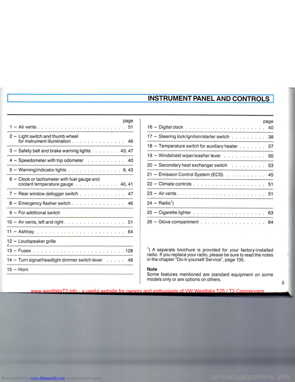
INSTRUMENT PANEL AND CONTROLS
page
1 - Air vents 51
2 - Light switch and thumb wheel for instrument illumination 46
3 - Safety belt and brake warning lights 43, 47
4 - Speedometer with trip odometer 40 5 — Warning/indicator lights 6, 43
6 - Clock or tachometer with fuel gauge and coolant temperature gauge 40,41
7 - Rear window defogger switch 47
8 - Emergency flasher switch 46 9 - For additional switch
10 - Air vents, left and right 51
11 - Ashtray 64
12 - Loudspeaker grille
13 - Fuses 128 14 - Turn signal/headlight dimmer switch lever 48
15 - Horn page
16 - Digital clock 40
17 - Steering lock/ignition/starter switch 38
18 - Temperature switch for auxiliary heater 57
19 - Windshield wiper/washer lever 50
20 - Secondary heat exchanger switch 53
21 - Emission Control System (ECS) 45
22 - Climate controls 51
23 - Air vents 51
24 - Radio1)
25 - Cigarette lighter 63 26 - Glove compartment 64
1) A separate brochure is provided for your factory-installed
radio.
If you replace your radio, please be sure to read the notes
in the chapter "Do-it-yourself Service", page 135.
Note
Some features mentioned are standard equipment on some
models only or are options on others.
www.westfaliaT3.info - a useful website for owners and enthusiasts of VW Westfalia T25 / T3 Campervans
Page 41 of 165
Downloaded from www.Manualslib.com manuals search engine
CONTROLS
AND
EQUIPMENT
INSTRUMENTCLUSTER
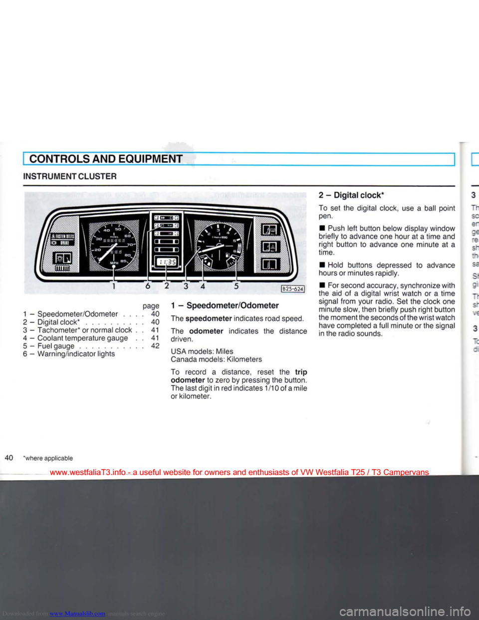
page
1 -
Speedometer/Odometer
.... 40
2
-
Digital clock*
40
3
-
Tachometer* or normal clock
. . 41
4
-
Coolant temperature gauge
. . 41
5
-
Fuel gauge
42
6
-
Warning/indicator lights
|B25-624J
1 -
Speedometer/Odometer
The
speedometer
indicates road
speed.
The
odometer
indicates
the
distance
driven.
USA
models: Miles
Canada
models: Kilometers
To record
a
distance, reset
the
trip
odometer to
zero by pressing the button.
The last
digit
in red indicates
1
/10 of a mile
or kilometer. 2
-
Digital
clock*
To
set the
digital clock, use
a
ball
point
pen.
•
Push
left
button
below display window
briefly
to
advance one hour
at a
time
and
right
button
to
advance
one
minute
at a
time.
•
Hold buttons depressed
to
advance
hours or minutes rapidly.
•
For second accuracy, synchronize
with
the
aid of a
digital
wrist
watch
or a
time
signal
from
your radio. Set the clock one minute slow, then briefly push
right
button
the moment the seconds of the
wrist
watch have completed a
full
minute or the signal
in the radio sounds.
40 *where applicable
www.westfaliaT3.info - a useful website for owners and enthusiasts of VW Westfalia T25 / T3 Campervans
Page 42 of 165
Downloaded from www.Manualslib.com manuals search engine
CONTROLS AND EQUIPMENT
I - Tachometer*
"he red shaded area at the end of the scale indicates the maximum permissible
engine rpm (revolutions per minute) for all gears after the break-in period. Before
'eaching this area, the next higher gear
snould be selected or the foot eased off
the accelerator pedal. Earlier shifting saves fuel and reduces noise.
Sniff to the next lower gear when the en-
; ne rpm drops below 1500 rpm.
~ne green shaded area on the scale snows the speed at which the engine is de-
•
eloping its most favourable torque.
3 - Normal clock*
~J
set the clock, depress the knob in the : al center and
turn.
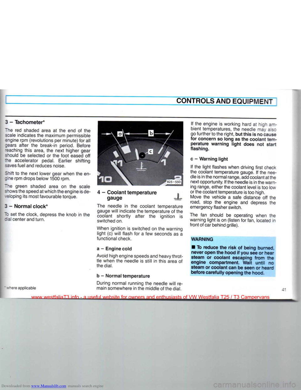
4 - Coolant temperature
gauge X
tare applicable The needle in the coolant temperature
gauge will indicate the temperature of the
coolant shortly after the ignition is
switched on.
When ignition is switched on the warning light (c) will flash for a few seconds as a
functional check.
a - Engine cold
Avoid high engine speeds and heavy throt tle when the needle is still in this area of
the
dial.
b - Normal temperature During normal running the needle will re
main somewhere in the middle of the
dial.
If the engine is working hard at hign a--
bient temperatures, the needle may as:
go further to the right, but this is no cause
for concern so long as the coolant
tem
perature warning light does not start
flashing.
c - Warning light If the light flashes when driving first check
the coolant temperature gauge. If the nee
dle is in the normal range, add coolant at the next opportunity. If the needle is in the warn
ing range, either the coolant level is too low
or the coolant temperature is too high. Move the vehicle a safe distance off the
road,
stop the engine and depress the
emergency flasher switch.
The fan should be operating when the warning light is on (listen for fan, located in
front of car behind grille).
WARNING • To reduce the risk of being burned,
never open the hood if you see or hear
steam or coolant escaping from the
engine compartment. Wait until no
steam or coolant can be seen or heard
before carefully opening the hood.
www.westfaliaT3.info - a useful website for owners and enthusiasts of VW Westfalia T25 / T3 Campervans
Page 58 of 165
Downloaded from www.Manualslib.com manuals search engine
AUXILIARY HEATER*
CONTROLS AND EQUIPMENT
~jrn the auxiliary heater on and off with the :amperature switch, located on the right of
fee steering column. Use the same switch
ID
regulate the heat.
depending on vehicle model, the warm air
lows from the footwell vents for the pas senger compartment and/or from a con-
tollable vent under the driving seat. The a r distribution cannot be controlled.
While driving, the heater can be operated rontinuously. When the engine is not run-
-:ng,
the heater will shut off automatically
after 10 minutes to save battery power.
"he auxiliary heater is running on fuel from our fuel tank. Fuel consumption varies
according to operating conditions and
-eat output (approx. 1 US qt or one liter
zer hour). 0
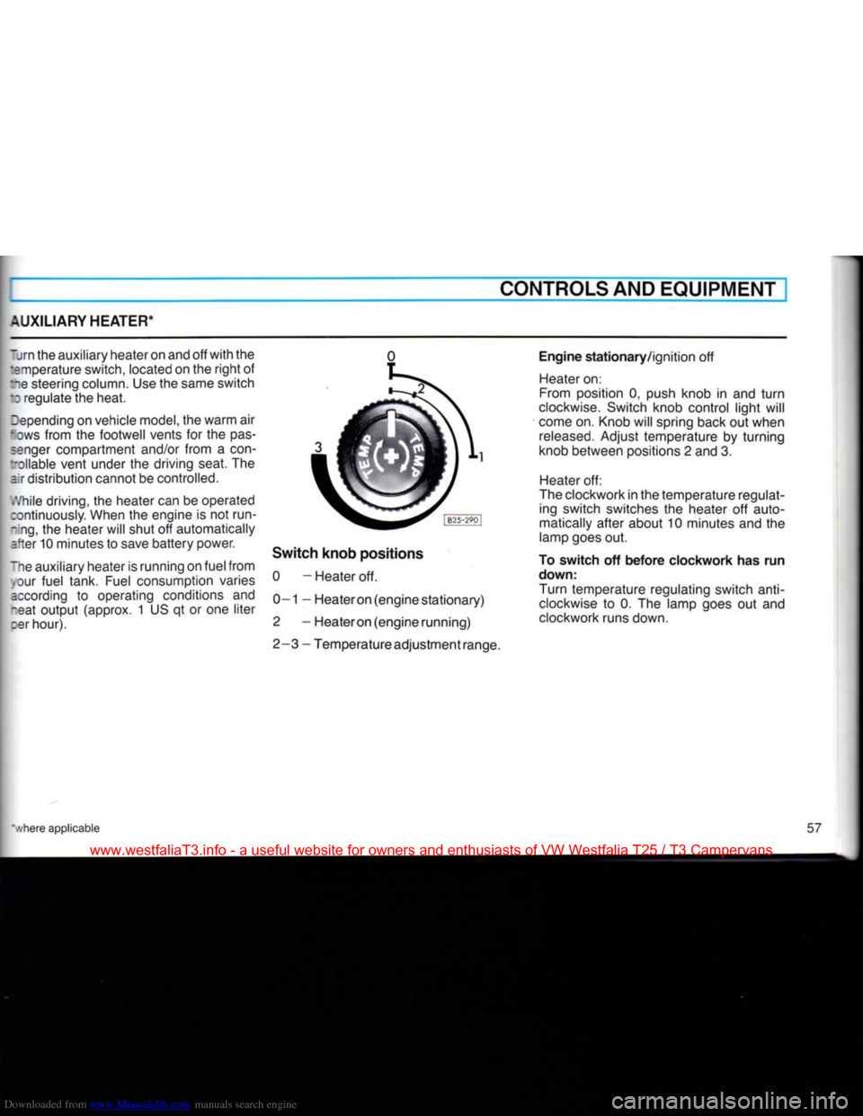
Switch knob positions 0 - Heater off.
0—1 — Heateron (engine stationary)
2 - Heateron (engine running)
2-3 - Temperature adjustment range. Engine stationary/ignition off
Heater on:
From position 0, push knob in and turn
clockwise. Switch knob control light will
come on. Knob will spring back out when
released.
Adjust temperature by turning
knob between positions 2 and 3.
Heater off:
The clockwork in the temperature regulat ing switch switches the heater off auto
matically after about 10 minutes and the
lamp goes out.
To switch off before clockwork has run
down:
Turn temperature regulating switch
anti
clockwise to 0. The lamp goes out and
clockwork runs down.
www.westfaliaT3.info - a useful website for owners and enthusiasts of VW Westfalia T25 / T3 Campervans
Page 59 of 165
Downloaded from www.Manualslib.com manuals search engine
CONTROLS AND EQUIPMENT
Engine
running
Heater
on -
Turn knob clockwise to position 2. Switch knob control light will come on. Adjust
temperature by turning knob between positions 2 and 3.
Heater
off -
Turn switch knob counter-clockwise to position 0. Switch knob control light will go
out.
Notes
• Every time the heater is switched off,
the warm air and combustion air blowers continue running briefly to cool the heater
down quicker.
• To avoid draining the battery, do not
run the heater repeatedly when the engine
is
not running.
• When the heater is running on the
clockwork time switch, it must be switched
off by hand before attempting to start the
engine at low temperatures so
that
the
full
battery capacity is available to
turn
the
engine.
WARNING
Never
start
the
heater
or let the
engine
or the
heater
run in an enclosed, un-
ventilated
area.
Exhaust
fumes
from
the
engine
or the
heater
contain
carbon monoxide,
which
is colorless and
odorless. Carbon monoxide,
however
is a
very
harmful
gas, and may be
fatal
if inhaled.
Due to the
risk
of
fire
the
heater
must
not be used
when
vehicle
is
parked
on
dry grass, brush or leaves.
Maintenance
During the winter and when driving over
very poor roads, mud or snow may tend to
accumulate
in the exhaust and combus
tion air intake pipes. Have these pipes
checked
for blockage from time to time so
that
the heater can continue to work.
58
www.westfaliaT3.info - a useful website for owners and enthusiasts of VW Westfalia T25 / T3 Campervans
Page 62 of 165

Downloaded from www.Manualslib.com manuals search engine
CONTROLS AND EQUIPMENT
Setting
the
time
•
Press
and hold clock button E.
• Set clock
with
buttons A.
The
display lights up as long as button is
oressed.
When button is released the dis
play goes out or, if a time has been pre
selected,
the selected time lights up for 2
sees.
To
switch
heater
on or off • This is done by pressing button
F.
When
-eater is switched on the warning lamp G ghts up.
To
ensure
that
the heater starts the lever ;or the heat output must be pushed fully to
:ie
right.
This
closes
an electrical contact.
Preselecting
starting
time
for
heater
stationary operation, ignition off)
With buttons C two different switch-on
:imes
can be selected within 24 hours.
•
Press
and hold button. The appropriate
*:gure 1 or 2 appears in display. The ready- •or-action lamp lights up.
• Set required switch-on time
with
but
tons A. The display remains on for about 20 seconds after releasing button C.
To
ensure
that
the heater starts up at the
selected
time, the lever for the heat output must be pushed fully over to the
right.
In
addition to this the blower must be
switched to Stage 1. On account of the higher current consumption, a higher
stage
should only be selected in isolated
cases.
Switching
preselected
time
off • The preselected time can be switched
off by briefly pressing the appropriate but
ton C. The ready-for-action lamp and the figure in display then go out.
Fuses
The
fuses for the auxiliary heater are in an additional holder behind the main fuse
box.
Notes
• Every time the heater is switched off,
the warm air and combustion air blowers
continue running briefly to cool the heater
down quicker.
• To avoid draining the battery, do not run
the heater repeatedly when the engine is not running.
• When driving through mud and snow,
the exhaust pipe may tend to get blocked.
Have
a look at it occasionally to see
that
it
is
clear.
WARNING
Never
start
the
heater
or let the
engine
or the
heater
run in an enclosed,
unventilated
area.
Exhaust
fumes
from
the
engine
or the
heater
contain
carbon monoxide,
which
is colorless and odor
less.
Carbon monoxide,
however
is a
very
harmful
gas, and may be
fatal
if in haled.
Due to the
risk
of
fire
the
heater
must
not be used
when
vehicle
is
parked
on
dry grass, brush or leaves.
www.westfaliaT3.info - a useful website for owners and enthusiasts of VW Westfalia T25 / T3 Campervans
Page 63 of 165
Downloaded from www.Manualslib.com manuals search engine
CONTROLS AND EQUIPMENT
SLIDING
ROOF*
SUN
ROOF*
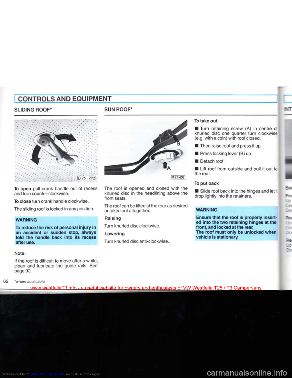
To open pull crank handle out of recess
and
turn
counter-clockwise.
To close
turn
crank handle clockwise.
The
sliding roof is locked in any position.
WARNING
To
reduce
the
risk
of personal
injury
in an
accident
or sudden stop,
always
fold
the
handle
back
into
its recess
after
use.
Note:
If the roof is difficult to move after a while,
clean
and lubricate the guide rails. See
page
92.
The
roof is opened and closed
with
the
knurled disc in the headlining above the
front
seats.
The
roof can be
tilted
at the rear as desired or taken out altogether.
Raising
Turn knurled disc clockwise.
Lowering
Turn knurled disc anti-clockwise. To
take
out
• Turn retaining screw (A) in centre of
knurled disc one quarter
turn
clockwise
(e.g.
with
a coin)
with
roof
closed.
• Then raise roof and press it up.
•
Press
locking lever (B) up. • Detach roof.
• Lift roof from outside and pull it out tc
the rear.
To put
back
• Slide roof back into the hinges and let it
drop lightly into the retainers.
WARNING
Ensure
that
the
roof
is
properly
insert
ed
into
the two
retaining
hinges at the
front,
and locked at the
rear.
The
roof
must
only
be unlocked
when
vehicle
is
stationary.
62 "where applicable
www.westfaliaT3.info - a useful website for owners and enthusiasts of VW Westfalia T25 / T3 Campervans
Page 131 of 165
Downloaded from www.Manualslib.com manuals search engine
DO-IT-YOURSELF-SERVICE
Step
3
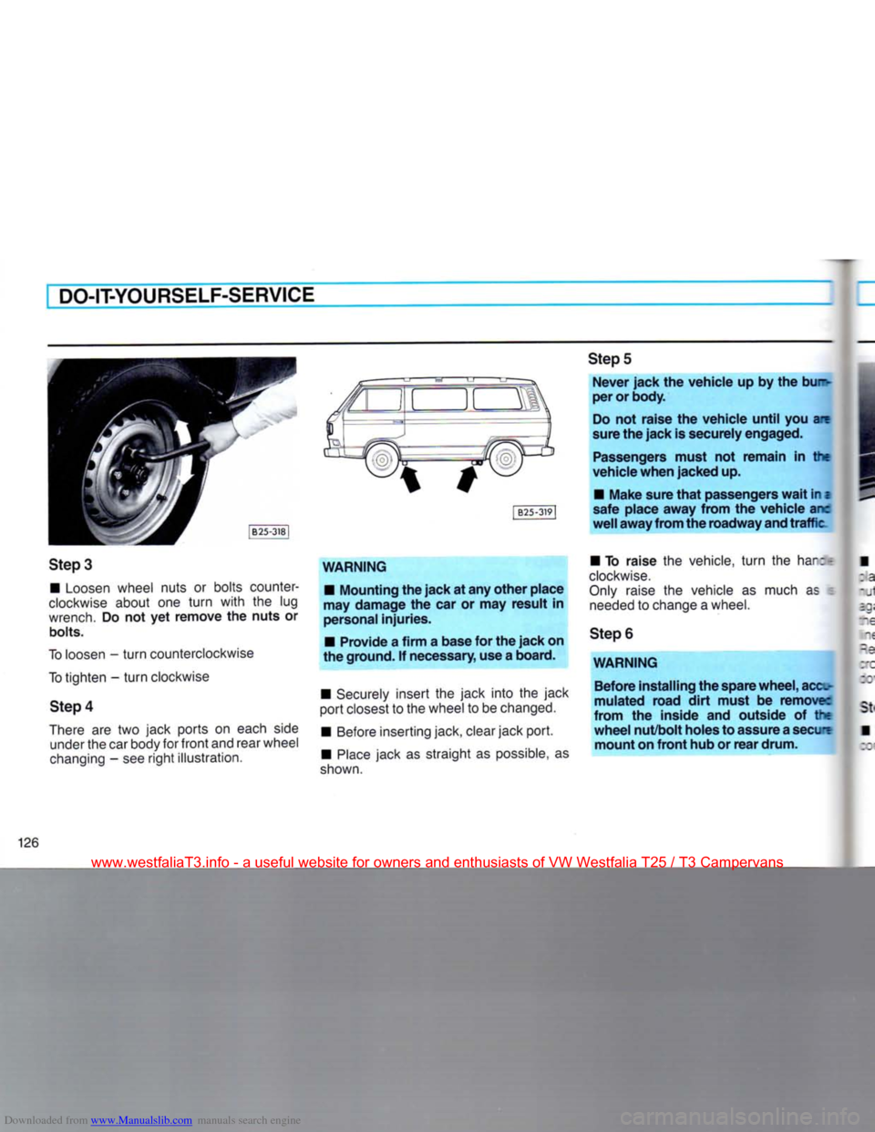
•
Loosen
wheel
nuts or bolts counter
clockwise
about one turn with the lug
wrench.
Do not yet remove the nuts or
bolts.
To
loosen
- turn
counterclockwise
To
tighten - turn
clockwise
Step
4
There
are two jack ports on
each
side
under
the car
body
for front and
rear
wheel
changing
- see right illustration. [
B25-3)9|
WARNING
•
Mounting the jack at any other place
may damage the car or may result in
personal
injuries.
•
Provide a firm a base for the jack on
the ground. If
necessary,
use a board.
•
Securely
insert the jack into the jack
port
closest
to the
wheel
to be
changed.
•
Before
inserting jack,
clear
jack port.
•
Place
jack as straight as
possible,
as
shown.
Step
5
Never jack the vehicle up by the bu~
per or body.
Do
not raise the vehicle until you are
sure
the jack is securely engaged.
Passengers
must not remain in the
vehicle when jacked up.
•
Make sure
that
passengers
wait
in z
safe place away from the vehicle arc
well
away from the roadway and traffic
•
To raise the
vehicle,
turn the
har:T
clockwise.
Only
raise
the
vehicle
as
much
as
needed
to
change
a
wheel.
Step
6
WARNING Before installing the spare wheel, acc-
mulated road
dirt
must be remove:
from the inside and outside of the
wheel nut/bolt holes to assure a secure mount on front hub or rear drum.
126
www.westfaliaT3.info - a useful website for owners and enthusiasts of VW Westfalia T25 / T3 Campervans