1990 VOLKSWAGEN TRANSPORTER set clock
[x] Cancel search: set clockPage 41 of 165

Downloaded from www.Manualslib.com manuals search engine
CONTROLS
AND
EQUIPMENT
INSTRUMENTCLUSTER
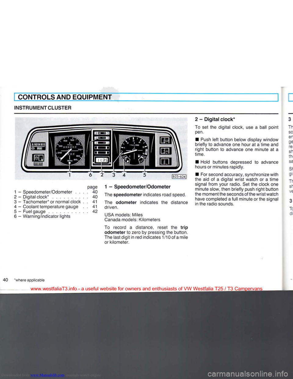
page
1 -
Speedometer/Odometer
.... 40
2
-
Digital clock*
40
3
-
Tachometer* or normal clock
. . 41
4
-
Coolant temperature gauge
. . 41
5
-
Fuel gauge
42
6
-
Warning/indicator lights
|B25-624J
1 -
Speedometer/Odometer
The
speedometer
indicates road
speed.
The
odometer
indicates
the
distance
driven.
USA
models: Miles
Canada
models: Kilometers
To record
a
distance, reset
the
trip
odometer to
zero by pressing the button.
The last
digit
in red indicates
1
/10 of a mile
or kilometer. 2
-
Digital
clock*
To
set the
digital clock, use
a
ball
point
pen.
•
Push
left
button
below display window
briefly
to
advance one hour
at a
time
and
right
button
to
advance
one
minute
at a
time.
•
Hold buttons depressed
to
advance
hours or minutes rapidly.
•
For second accuracy, synchronize
with
the
aid of a
digital
wrist
watch
or a
time
signal
from
your radio. Set the clock one minute slow, then briefly push
right
button
the moment the seconds of the
wrist
watch have completed a
full
minute or the signal
in the radio sounds.
40 *where applicable
www.westfaliaT3.info - a useful website for owners and enthusiasts of VW Westfalia T25 / T3 Campervans
Page 42 of 165

Downloaded from www.Manualslib.com manuals search engine
CONTROLS AND EQUIPMENT
I - Tachometer*
"he red shaded area at the end of the scale indicates the maximum permissible
engine rpm (revolutions per minute) for all gears after the break-in period. Before
'eaching this area, the next higher gear
snould be selected or the foot eased off
the accelerator pedal. Earlier shifting saves fuel and reduces noise.
Sniff to the next lower gear when the en-
; ne rpm drops below 1500 rpm.
~ne green shaded area on the scale snows the speed at which the engine is de-
•
eloping its most favourable torque.
3 - Normal clock*
~J
set the clock, depress the knob in the : al center and
turn.
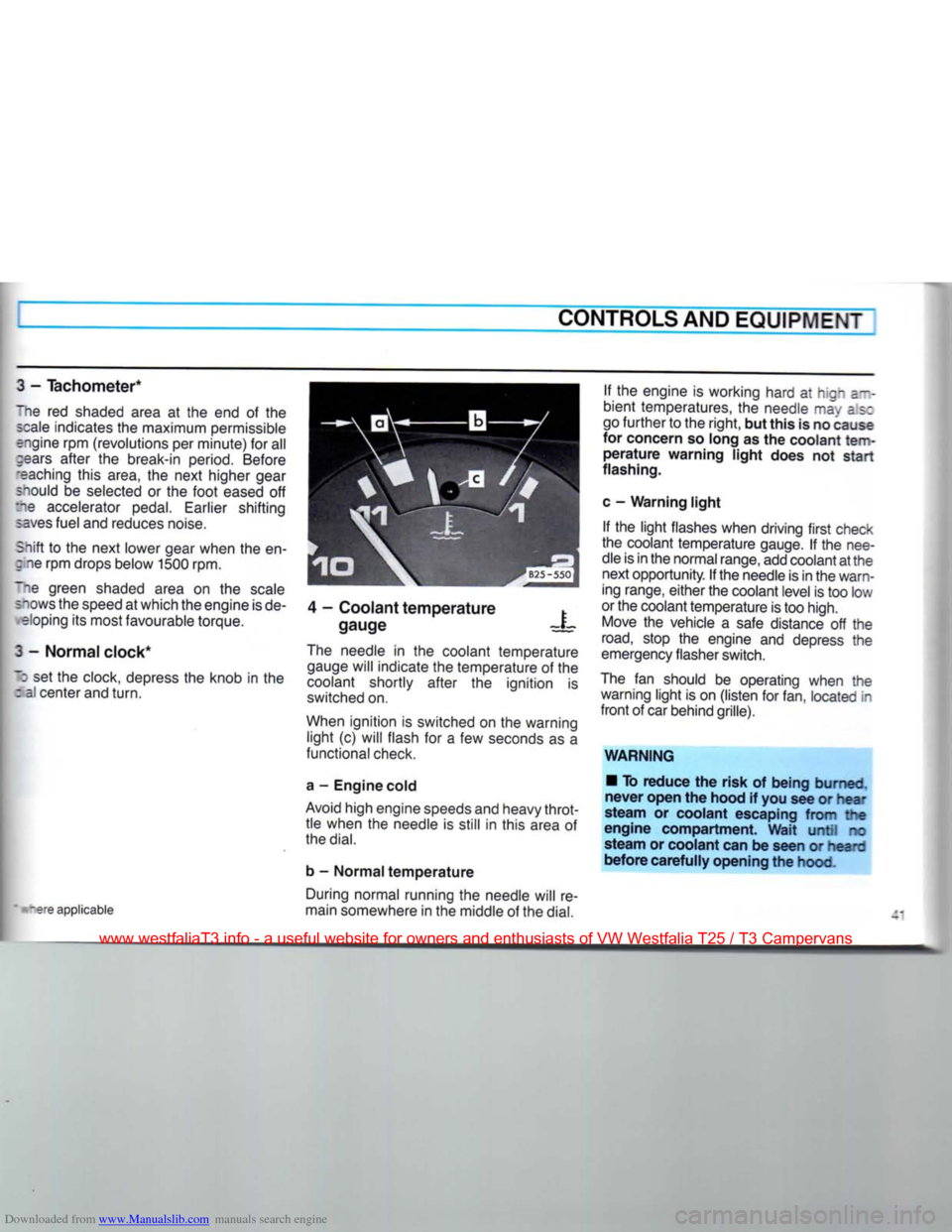
4 - Coolant temperature
gauge X
tare applicable The needle in the coolant temperature
gauge will indicate the temperature of the
coolant shortly after the ignition is
switched on.
When ignition is switched on the warning light (c) will flash for a few seconds as a
functional check.
a - Engine cold
Avoid high engine speeds and heavy throt tle when the needle is still in this area of
the
dial.
b - Normal temperature During normal running the needle will re
main somewhere in the middle of the
dial.
If the engine is working hard at hign a--
bient temperatures, the needle may as:
go further to the right, but this is no cause
for concern so long as the coolant
tem
perature warning light does not start
flashing.
c - Warning light If the light flashes when driving first check
the coolant temperature gauge. If the nee
dle is in the normal range, add coolant at the next opportunity. If the needle is in the warn
ing range, either the coolant level is too low
or the coolant temperature is too high. Move the vehicle a safe distance off the
road,
stop the engine and depress the
emergency flasher switch.
The fan should be operating when the warning light is on (listen for fan, located in
front of car behind grille).
WARNING • To reduce the risk of being burned,
never open the hood if you see or hear
steam or coolant escaping from the
engine compartment. Wait until no
steam or coolant can be seen or heard
before carefully opening the hood.
www.westfaliaT3.info - a useful website for owners and enthusiasts of VW Westfalia T25 / T3 Campervans
Page 62 of 165

Downloaded from www.Manualslib.com manuals search engine
CONTROLS AND EQUIPMENT
Setting
the
time
•
Press
and hold clock button E.
• Set clock
with
buttons A.
The
display lights up as long as button is
oressed.
When button is released the dis
play goes out or, if a time has been pre
selected,
the selected time lights up for 2
sees.
To
switch
heater
on or off • This is done by pressing button
F.
When
-eater is switched on the warning lamp G ghts up.
To
ensure
that
the heater starts the lever ;or the heat output must be pushed fully to
:ie
right.
This
closes
an electrical contact.
Preselecting
starting
time
for
heater
stationary operation, ignition off)
With buttons C two different switch-on
:imes
can be selected within 24 hours.
•
Press
and hold button. The appropriate
*:gure 1 or 2 appears in display. The ready- •or-action lamp lights up.
• Set required switch-on time
with
but
tons A. The display remains on for about 20 seconds after releasing button C.
To
ensure
that
the heater starts up at the
selected
time, the lever for the heat output must be pushed fully over to the
right.
In
addition to this the blower must be
switched to Stage 1. On account of the higher current consumption, a higher
stage
should only be selected in isolated
cases.
Switching
preselected
time
off • The preselected time can be switched
off by briefly pressing the appropriate but
ton C. The ready-for-action lamp and the figure in display then go out.
Fuses
The
fuses for the auxiliary heater are in an additional holder behind the main fuse
box.
Notes
• Every time the heater is switched off,
the warm air and combustion air blowers
continue running briefly to cool the heater
down quicker.
• To avoid draining the battery, do not run
the heater repeatedly when the engine is not running.
• When driving through mud and snow,
the exhaust pipe may tend to get blocked.
Have
a look at it occasionally to see
that
it
is
clear.
WARNING
Never
start
the
heater
or let the
engine
or the
heater
run in an enclosed,
unventilated
area.
Exhaust
fumes
from
the
engine
or the
heater
contain
carbon monoxide,
which
is colorless and odor
less.
Carbon monoxide,
however
is a
very
harmful
gas, and may be
fatal
if in haled.
Due to the
risk
of
fire
the
heater
must
not be used
when
vehicle
is
parked
on
dry grass, brush or leaves.
www.westfaliaT3.info - a useful website for owners and enthusiasts of VW Westfalia T25 / T3 Campervans
Page 136 of 165

Downloaded from www.Manualslib.com manuals search engine
DO-IT-YOURSELF-SERVICEI
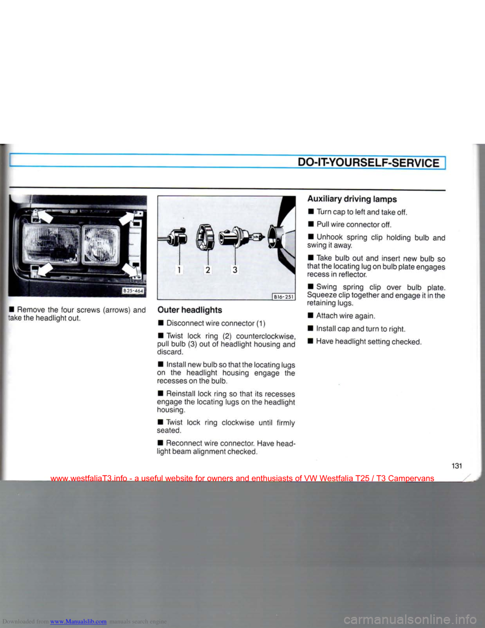
• Remove the four screws (arrows) and
take the headlight out. | B16-251
Outer
headlights
• Disconnect wire connector (1)
• Twist lock ring (2) counterclockwise,
pull bulb (3) out ot headlight housing and
discard.
• Install new bulb so
that
the locating lugs
on the headlight housing engage the
recesses
on the bulb.
• Reinstall lock ring so
that
its recesses
engage
the locating lugs on the headlight
housing.
• Twist lock ring clockwise until firmly
seated.
• Reconnect wire connector. Have head
light beam alignment checked.
Auxiliary
driving
lamps
• Turn cap to
left
and take off.
• Pull wire connector off.
• Unhook spring clip holding bulb and
swing it away.
• Take bulb out and insert new bulb so
that
the locating lug on bulb plate engages
recess
in reflector.
• Swing spring clip over bulb plate.
Squeeze
clip together and engage it in the retaining lugs.
• Attach wire again.
• Install cap and
turn
to
right.
• Have headlight setting checked.
131
www.westfaliaT3.info - a useful website for owners and enthusiasts of VW Westfalia T25 / T3 Campervans