Page 145 of 391

FUEL SYSTEM- Fuel Injection Control14-33
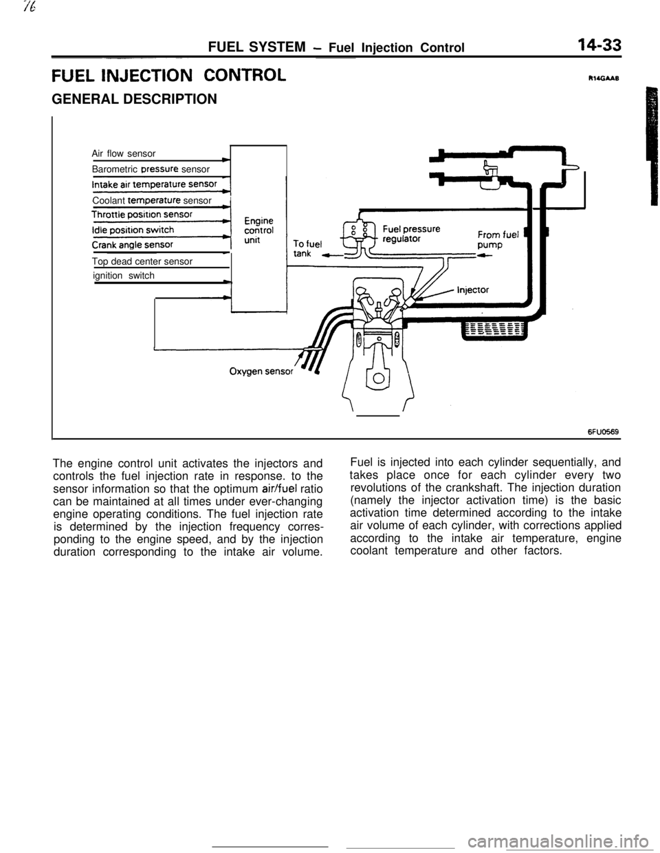
FUEL INJECTI& CONTROLGENERAL DESCRIPTION
Air flow sensor
cBarometric Dressure sensor
Coolant
temr3erature sensorITop dead center sensor
ignition switch
-
c
6FUO569The engine control unit activates the injectors andFuel is injected into each cylinder sequentially, and
controls the fuel injection rate in response. to thetakes place once for each cylinder every two
sensor information so that the optimum
air/fuel ratiorevolutions of the crankshaft. The injection duration
can be maintained at all times under ever-changing(namely the injector activation time) is the basic
engine operating conditions. The fuel injection rateactivation time determined according to the intake
is determined by the injection frequency corres-air volume of each cylinder, with corrections applied
ponding to the engine speed, and by the injectionaccording to the intake air temperature, engine
duration corresponding to the intake air volume.coolant temperature and other factors.
Page 146 of 391
-
14-34FUEL SYSTEM - Fuel Injection Control
TDC sensorAir flow sensor
I
Reading of input signal1
I ,,
uOperation mode decisionOperation mode decision data
I rBasic valve opening time data
Enginecontrol unitInjector activation time control
Injector activation pulse generationControl factor data of
engine coolant temperature,
intake air temperature and
barometric pressure, etc.
Injector1
6FUO766Needle valveFilter
Connector
Solenoid coil
Plunger
-4
INJECTOR,
The injection nozzle spray opening area is constant and the fuelinjection pressure is also constant; therefore, the injection
quantity is determined by the amount of time that the solenoid
coil is energized.
.
Page 148 of 391

14-36FUEL SYSTEM- Fuel lniection Control
SFUOSlS
RESISTOR The resistor functions to regulate the current flowing in the
co,.of the injector.
Because the injector must respond instantly to fuel-injection
signals, the number of windings of the coil is reduced in order
to facilitate current rise when the current is flowing in the coil.
By doing so, the resistance of the injector coil becomes smaller
and a greater amount of current can flow, with the result that
the calorific value of the injector coil becomes greater, and
1overheating occurs.
For this reason, for turbocharger-equipped models (which have
low resistance of the injector coil), a resistor is provided
between the power supply (+) and the injector in order to
regulate the amount of current flowing in the coil.
FUEL INJECTION TIMING (INJECTOR AC-
TIVATION TIMING)
The fuel injection timing in multipoint fuel injection
has two modes, sequential and simultaneous. In
sequential injection, fuel is injected into each
cyl-inder sequentially throughout the entire normaloperating range including idling; in simultaneous
injection, fuel is injected simultaneously into all
cylinders during starting and acceleration.
Sequential Injection
r
No. 1cylinder
TDC sensor signal
Crank angle
sensor signal
No. 1 cylinder
No. 3 cylinder
No. 4 cylinder
No. 2 cylinder
In sequential injection, the’ injectors are activated foreach cylinder on the combustion stroke of the
piston. The No. 1 cylinder TDC signal is the
refer-
ence signal for sequential injection. The signal
represents the compression stroke in the No.
1cylinder and, with that timing as a reference, fuel isinjected into the cylinders in the order of
No.2,No.
1, No.3, and No.4. The injection for each
cylinder is synchronized with the crank angle
sen-sor’s 5” BTDC signal. Fuel is injected in each
cylinder once for every two revolutions of the
crankshaft.
-
Page 149 of 391

FUEL SYSTEM -Fuel Injection Control14-37Simultaneous Injection
INJECTION UPON START CRANKING
TDC sensor signal
Crank angle
sensor signal
No.
1 cylinder
No. 3 cylinder
No. 4 cylinder
No. 2 cylinder
TDC
IntakeCombustion
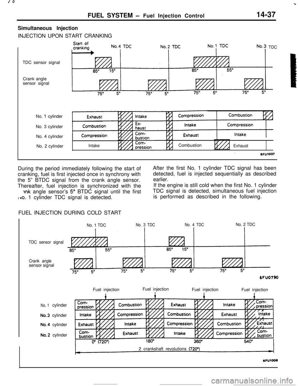
ExhaustDuring the period immediately following the start ofAfter the first No. 1 cylinder TDC signal has been
cranking, fuel is first injected once in synchrony withdetected, fuel is injected sequentially as described
the 5” BTDC signal from the crank angle sensor.
earlier.Thereafter, fuel injection is synchronized with theIf the engine is still cold when the first No. 1 cylinder
jnk angle sensor’s 5” BTDC signal until the firstTDC signal is detected, simultaneous fuel injection
i~o. 1 cylinder TDC signal is detected.is performed as described in the following.
FUEL INJECTION DURING COLD START
No. 1 TDCNo. 3 TDCNo. 4 TDCNo. 2 TDC
TDC sensor signal
Crank anglesensor signal
No. 1cylinderNo.3cylinderNo.4cylinderNo.2cylinder
6FUO790Fuel injection
1Fuel injection
Fuel injection1Fuel injection12 crankshaft revolutions
(720’)
Page 150 of 391
FUEL SYSTEM - Fuel Injection Control
When cranking the cold engine, fuel is injected into
all four cylinders simultaneously twice for every
crankshaft revolution, and fuel injection is synchro-
nized with the crank angle sensor’s 5” BTDC signal.
INCREASED FUEL INJECTION DURING ACCELERATION
No.1 TDC
TDC sensor signal
85”Crank angle
sensor signal
No.
1 cylinderINo. 3 cylinder
IIntakeNo.3 TDC
INo.4 TDCIIncreased fuel injection
during acceleratiqn
8
bxhaustNo. 4 cylinder
No. 2 cylinder
During acceleration, an increased amount of fuel
according to the degree of acceleration is injected
simultaneously into all four cylinders every 10
msecs., in addition to the sequential injection.
-
Page 151 of 391

FUEL SYSTEM- Fuel Injection Control14-39FUEL INJECTION AMOUNT CONTROL (INJECTOR ACTIVATION DURATION CON-
TROL)
bntrol during Normal Operating Conditions
Open loop control
( ArrflowsensorBasic driving
time deter-
-”mination
i( Injected fuel
amount control
s depending on
engine coolant
temperature
I
II
””compensatron
Injected fuel Injected fuel
c amount control t-c amount control t-during accel-during accel-4 4eration and eration anddeceleration decelerationIIInjector Injector
+ Batten/voltage --W+ Batten/voltage --Wcompensation compensation
QQ44=I,=I,f \f \6FU07M6FU07Mtemperature
II
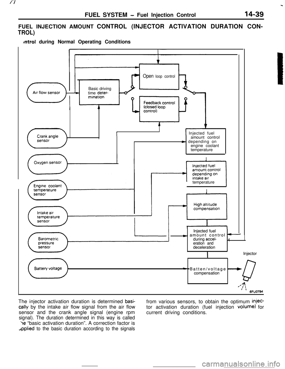
The injector activation duration is determined
basi-
tally by the intake air flow signal from the air flow
sensor and the crank angle signal (engine rpm
signal). The duration determined in this way is called‘le “basic activation duration”. A correction factor is
applied to the basic duration according to the signalsfrom various sensors, to obtain the optimum
injec-tor activation duration (fuel injection volume) for
current driving conditions.
Page 152 of 391

14-40FUEL SYSTEM - Fuel Injection Control
BASIC INJECTOR ACTIVATION DURATION
In sequential injection under normal operating conditions, fuel
is injected into each cylinder once every cycle (i.e., two
crankshaft revolutions).
The injector activation duration required to inject the amount of
fuel that achieves the stoichiometric air-fuel ratio
(15 times as
much air, by weight, as gasoline, by weight) with regard to the
amount of air admitted during one cycle in each cylinder is
called the “basic injector activation duration”.
The amount of air admitted to each cylinder during one cycle is
calculated by the engine control unit based on the signals
provided by the air flow sensor and crank angle sensor.
FOR YOUR INFORMATION:
Crankangle
sensor
signal, Engine one revolution .
I
TtI
t--“---t-+[Calculation of the Amount of Intake Air into Each Cylinder
during One Cycle]
The amount of intake air used by the four cylinders in one cycle
in a four-cylinder engine can be calculated by counting the
number of pulses output from the air flow sensor during the
period of time in which the crankshaft rotates two complete
revolutions, i.e., during which four complete pulses are output
from the crank angle sensor. The amount of intake air used by
each cylinder in one cycle can therefore be calculated by
counting the number of air flow sensor output pulses during
the time in which the crank angle sensor outputs one pulse.
The amount of intake air into each cylinder per cycle is denoted
by the symbol
A/N, which varies in proportion to the intake
manifold vacuum (absolute pressure).
[Calculation of the Engine
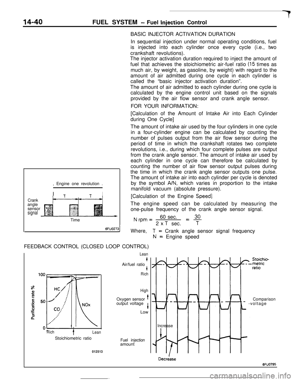
Speed]The engine speed can be calculated by measuring the
one-pulse frequency of the crank angle sensor signal.
Nrpm=60 sec.L!!L2
x T sec.TTime
6FUO27:31Where,FEEDBACK CONTROL (CLOSED LOOP CONTROL)
i
Rich1Lean
T= Crank angle sensor signal frequency
N= Engine speed
Lean
kAir/fuel ratiot
Rich
HighOxygen sensor
toutput voltage
1Low
Stoichiometric ratio
Fuel injectionamount
012513
I-
Lt
Comparison- -voltage
Increase
j/
Decriase
6FUO795
Page 153 of 391

FUEL SYSTEM -Fuel Injection Control
14-41
During normal operation (including idling), the en-
gine control unit controls the injector activation time
tcThieve the stoichiometric air/fuel ratio, which
e.;res maximum efficiency of the catalytic conver-
ter, on the basis of the oxygen sensor signal.
When the air/fuel mixture is richer than the
stoichiometric ratio, there is less oxygen in the
exhaust gas and thus the oxygen sensor output
voltage is higher; hence a “mixture rich” signal is
input to the engine control unit. Then, the engine
control unit decreases the amount of fuel injected. If
the air/fuel ratio decreases to the point that and the
mixture becomes leaner than the stoichiometric
ratio, the oxygen concentration in the exhaust gas
increases and the oxygen sensor output voltage
becomes lower. Then, a “mixture lean” signal isinput to the engine control unit.
Upon input of this signal, the engine control unit
increases the feedback correction factor, thus caus-
ing more fuel to be injected.
By means of the above-mentioned controls (collec-
tively called “feedback control”), the air-fuel mixture
is maintained at the stoichiometric ratio.
Under the following specific conditions, this feed-
back control is not performed, in order to improve
driveability.
(11
(2)
::I
(5)While cranking the engine
During engine warm-up when engine coolant
temperature is less than
45°C (113°F)During acceleration/deceleration
During high load operation
When oxygen sensor is not functioning
IOPEN LOOP CONTROL
Engine speed rpm6FUO274
II
80(176)
Coolant temperature “C (“Fj6FlJO276
I425(77)
Intake air temperature “C (“F)1~40,0IThe amount of fuel injected is controlled according to the map
value* preset for each engine speed and A/N (refer to
P.l4-39FOR YOUR INFORMATION).
*Map value: Value preset and stored in the ROM of the engine
control unit.
ENRICHMENTWhen the throttle valve is wide open, control is performed to
increase the amount of fuel injected, in order to secure good
driveability under high load conditions.
FUEL INJECTION CONTROL DURING ENGINE WARM-UP
To secure good driveability when the engine is still cold, control
is performed to increase the amount of fuel injected when the
engine
cooiant temperature is low.
FUEL INJECTION CONTROL ACCORDING TO INTAKE AIR
TEMPERATUREGiven a constant intake air volume, the change in intake air
temperature alters the intake air density, resulting in an
improper air-fuel ratio.
To correct this deviation, the amount of fuel injected is
controlled; i.e., the amount of fuel injected is increased to
compensate for the higher
intake air density caused by the
decreased intake air temperature.