1990 MITSUBISHI ECLIPSE catalytic converter
[x] Cancel search: catalytic converterPage 87 of 391

=--Y
jl
1 /
i "
_. ---“._ _ _ ._ ..-..+_LI_y_--- -
9-2ENGINE- General Information
GENERAL INFORMATION
MAJOR
SPEClFlCATiONS
Row- -
Items
Number and arrangement of cylinderCylinder bore x stroke
mm (in.)
Total displacementcc (cu.in.1Compression ratio
Combustion chamber
Valve mechanismNumber of valve
Intake
Exhaust
Valve timing
IntakeOpen/CloseExhaust Open/Close
Lubrication
Oil pump
Fuel system
SuperchargerCooling system
Water pump
Alternator
Starter motor
Ignition system
Exhaust gas recirculation systemCatalytic converter
Crankcase ventilation system
Evaporative emission control system
Non-Turbo engineTurbo engine4 in-line, longitudinal
4 in-line, longitudinal
85 x
88 (3.346 x 3.465)85 x 88 (3.346 x 3.465)1997 (121.9)
1997 (121.7)
9.07.8
Pentroof typePentroof type
Double overhead camshaftDouble overhead camshaft
(DOHC)(DOHC)
88
88
26 “BTDU46”ABDC21”BTDC/Sl”ABDC56BBDUS”ATDC55”BBDUS”ATDC
Pressure feed-full flow filtrationPressure feed-full flow filtration
Gear typeGear type
Electronic control multipoint
fuelElectronic control multipoint fuel
injectioninjection
Turbo typeLiquid cooled-forced circulationLiquid cooled-forced circulation
-Impeller typeImpeller type
AC generator with a built-involtage regulatorAC generator with a built-in
voltage regulator
Planetary gear reduction drivePlanetary gear reduction drivetype
Two-coil type, electronic controlTwo-coil type, electronic control
ignitionignition
Conventional type: For FederalConventional type: For Federal
and Canadaand Canada
Electronical control type:Electronical control type:
For CaliforniaFor CaliforniaMonolithic type,
under-floorMonolithic type, under-floor
installationinstallation
Closed typeClosed type
Charcoal canister typeCharcoal canister type
I
Page 112 of 391

INTAKE AND EXHAUST - Exhaust PipeII-5
EXHAUST PIPERllDAM
,le exhaust pipe is supported from the body by
using rubber hangers and, in addition, a flexible pipe
is used at the front exhaust pipe in order to reducethe transmission of vibrations from the exhaust
system to the body.
CONSTRUCTION DIAGRAM
Center exhaust pipeFront exhaust pipe
IPm-muffler
Catalytic converter
Imuffler
IFront exhaust pipeCatalytic convener
Flexible pipe,05AO155
05A0157
Front exhakt pipeCatalytic converter
Page 133 of 391

FUEL SYSTEM - Sensors14-21When exposed to light, the photo diode conducts
urrent in a direction opposite to an ordinary diode.
.s a result, current flows in the direction indicated
by the arrow and dotted line and a voltage (5 volts) isapplied to the comparator of the sensor unit so that
the terminal voltage of the engine control unit
becomes 5 volts. When the disc rotates further andthe slit moves beyond the space between the
LED/photo diode pair, the light can no longer reach
the photo diode, thus the current indicated by the
dotted line ceases to flow and the terminal voltage
of the engine control unit becomes 0 volt.
tn this
way, pulse signals are sent to the engine control
unit from the sensor unit.
OXYGEN SENSOR
k
1 ~~~~t13ate~ousingCoverLead wiresConnectorHeater
Enginecontrol unit6FUlOO5
- Oxygen‘-serisor
The oxygen sensor is mounted at the outlet of the exhaust
manifold or the turbocharger. The sensor, which uses an
oxygen concentration cell having a, solid electrolyte, has such
characteristics that its output voltage changes sharply in the
vicinity of the stoichiometric air/fuel ratio.
The sensor makes use of this characteristic to detect oxygen
concentration in the exhaust gas and feeds back the signal to
the engine control unit, which then decides if the air/fuel ratio is
rich or iean relative to the stoichiometric ratio.
Based on this decision, the air/fuel ratio is feedback-controlled
to achieve the stoichiometric ratio at which the catalytic
converter operates most effectively.
In addition, because this oxygen sensor incorporates a heater,
the response of the sensor is good even if the temperature of
the exhaust gas is low, and, as a result, feedback control of the
air/fuel ratio is possible for a short time after the engine is
started.
Stoichiometric air/fuel ratlo
r3
Lean
Air/fuel ratioEC1007
Page 373 of 391

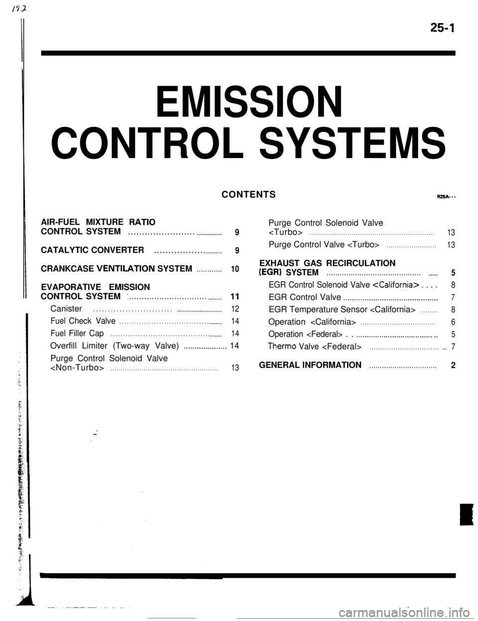
25-1
EMISSION
CONTROL SYSTEMSCONTENTS
RZSA---AIR-FUEL MIXTURE
RATIOCONTROL SYSTEM
. . . . . . . . . . . . . . . . . . . . . . . . .._.................9CATALYTIC CONVERTER
. . . . . . . . . . . . . . . . . .._............9CRANKCASE VENTlLATlON SYSTEM
. . . . . . . . . . . .10EVAPORATIVE EMISSION
CONTROL SYSTEM
: . . . . . . . . . . . . . . . . . . . . . . . . . . . . . . . ..-.........11Canister
. . . . . . . . . . . . . . . . . . . . . . . . . . . ..~...................._._...__..12
FuelCheck Valve. . . . . . . . . . . . . . . . . . . . . . . . . . . . . . . . . . . . .._.........14
FuelFiller Cap. . . . . . . . . . . . . . . . . . . . . . . . . . . . . . . . . . . . . . . . ..__....._..14Overfill Limiter (Two-way Valve)
_................... 14
Purge Control Solenoid Valve
. . . . . . . . . . . . . . . . . . . . . . . . . . . . . . . . . . . . . . . . . . . . . . . . . . . .13Purge Control Solenoid Valve
. . . . . . . . . . . _ . . . . . . . . . . . . . . . . . . . . . . . . . . . . . . . . . . . . . . . . . . . . . . . .13Purge Control Valve
. . . . . . . . . . . . . . . . . . . . . . . .13EXHAUST GAS RECIRCULATION
(EGR) SYSTEM. . . . . . . . . . . . . . . . . . . . . . . . . . . . . . . . . . . . . . . . . . . ..-......5
EGR Control Solenoid Valve
..,.........................................7EGR Temperature Sensor
. . . . . . . .8Operation
. . . . . . . . . . . . . . . . . . . . . . . . . . . . . . . . . . . .6
Operation
Therm0 Valve
. . . . . . . . . . . . . . . . . . . . . . . . . . . . . . . .2
Page 374 of 391

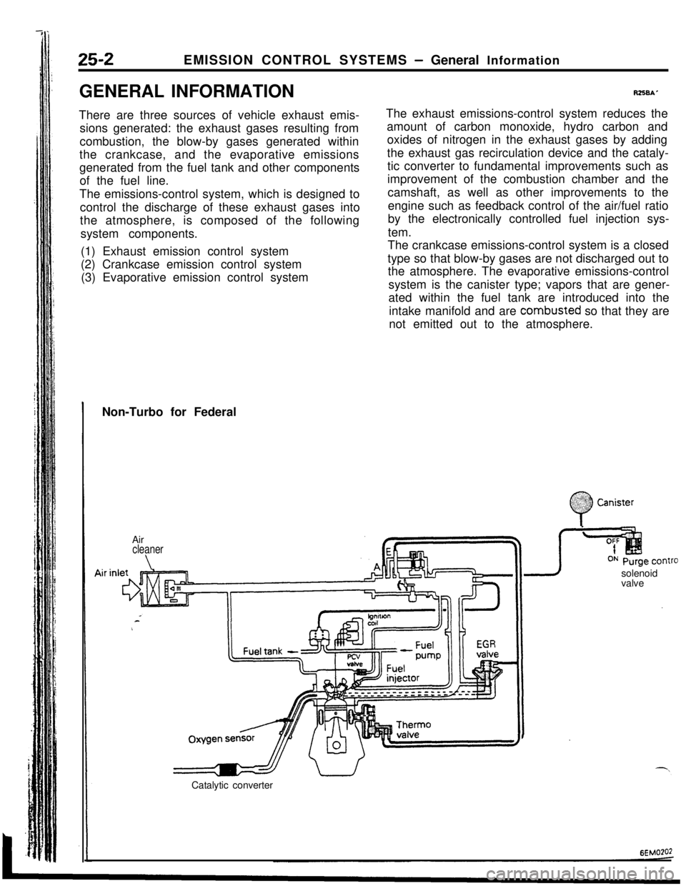
25-2EMISSION CONTROL SYSTEMS - General Information
GENERAL INFORMATION
There are three sources of vehicle exhaust emis-
sions generated: the exhaust gases resulting from
combustion, the blow-by gases generated within
the crankcase, and the evaporative emissions
generated from the fuel tank and other components
of the fuel line.
The emissions-control system, which is designed to
control the discharge of these exhaust gases into
the atmosphere, is composed of the following
system components.
(1) Exhaust emission control system
(2) Crankcase emission control system
(3) Evaporative emission control system
R258A’The exhaust emissions-control system reduces the
amount of carbon monoxide, hydro carbon and
oxides of nitrogen in the exhaust gases by adding
the exhaust gas recirculation device and the cataly-
tic converter to fundamental improvements such as
improvement of the combustion chamber and the
camshaft, as well as other improvements to the
engine such as feedback control of the air/fuel ratio
by the electronically controlled fuel injection sys-
tem.
The crankcase emissions-control system is a closed
type so that blow-by gases are not discharged out to
the atmosphere. The evaporative emissions-control
system is the canister type; vapors that are gener-
ated within the fuel tank are introduced into the
intake manifold and are combusted so that they are
not emitted out to the atmosphere.
Non-Turbo for Federal
Air
cleaner
\solenoid
valve
Catalytic converter
:
0
$2:) Canister:.:
Page 375 of 391

25-1
Eh/llSSlON
CONTROL SYSTEMS
rps*---
AIR-FUEL MIXTURE RATIO
_ . . . . . . . . . . . . . . . . . . . . . . . . . . . . . . . . . . .
CATALYTIC CONVERTER . . . . . . . . . . . . . . . . . . . . . . . . . . . . . . . .
._ _.__.____.
EVAPORATIVE EMISSION
: . . . . . . . . . . . . . . .._............. _ _.I.........
Canister . . . . . . . . . . . . . . . . . . . . . . . . . . . . . . . . . . . . \
. . . . . . . . . . . . . . . . . . . ..-..
Fuel Check Valve . . .._......._....._......__...._.__.............
Fuel Filler CapI.........._........................................
Overfill Limiter (Two-way Valve)_......._._.._._....
Purge Control Solenoid Valve
.._. _...
9
_..._............................................... 5
EGR Control Solenoid Valve
EGR Control Valve . . . . . . . . . . . . . . .._........................... 7
EGR Temperature Sensor
.._................ 6
Operation
Therm0 Valv e
GENERAL INFORMATIO N. . . . . . . . . . . . . . . . . . . . . . . . . . . . . . . . 2
Page 376 of 391

--.
25-2EMISSION CONTROL SYSTEMS - General Information
GENERAL INFORMATION
There are three sources of vehicle exhaust emis-
sions generated: the exhaust gases resulting from
combustion, the blow-by gases generated within
the crankcase, and the evaporative emissions
generated from the fuel tank and other components
of the fuel line.
The emissions-control system, which is designed to
control the discharge of these exhaust gases into
the atmosphere,is composed of the following
system components.
(1) Exhaust emission control system
(2) Crankcase emission control system
(3) Evaporative emission control system
RZSBAThe exhaust emissions-control system reduces the
amount of carbon monoxide, hydro carbon and
oxides of nitrogen in the exhaust gases by adding
the exhaust gas recirculation device and the cataly-
tic converter to fundamental improvements such as
improvement of the combustion chamber and the
camshaft, as well as other improvements to the
engine such as feedback control of the air/fuel ratio
by the electronically controlled fuel injection sys-
tem.
The crankcase emissions-control system is a closed
type so that blow-by gases are not discharged out to
the atmosphere. The evaporative emissions-control
system is the canister type; vapors that are gener-
ated within the fuel tank are introduced into the
intake manifold and are combusted so that they are
not emitted out to the atmosphere.
Non-Turbo for Federal
.;. :
0
.%??? CanisterAir
cleaner
\valveOxygenFuel tank
-a I”’ ,T
sensr’
Catalytic converter
6EMO?O2
Page 377 of 391

EMISSION CONTROL SYSTEMS - General Information25-3
INon-Turbo for California
Q
&i,& Canister<; /’Aircleaner\
hrinlet &j=-=&=p==~
oxz pJCatalytic converterEGR temperature sensor
ON Purge control
solenoid
valve
EGR controlsolenoid valve
Turbo for FederalAir
cleper
E
-II 11-l I-d-h I
-u’Catalytic a3nverter
in
Purge controlsolenoid
valve
6EM0260