Page 271 of 391

AUTOMATIC TRANSAXLE - Transaxle Control21-47
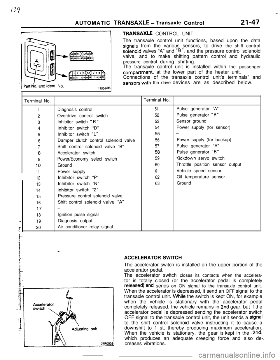
+TFWNSAXLE CONTROL UNIT
Part b!o. and Ident. No.17504The transaxle control unit functions, based upon the data
signals from the various sensors, to drive the shift controlsolenoid valves “A” and
“B”, and the pressure control solenoid
valve, and to make shifting pattern control and hydraulic
pressure control during shifting.
The transaxle control unit is installed within the passengercompartment, at the lower part of the heater unit.
Connections of the transaxle control unit’s terminals” and
sensors with the drive devices are as described below.
Terminal No.Terminal No.
1Diagnosis control51Pulse generator “A”
2Overdrive control switch52Pulse generator “B”
3Inhibitor switch e R U53Sensor ground
4Inhibitor switch “D”
54Power supply (for sensor)
5Inhibitor switch “L”55 -
6Damper clutch control solenoid valve56Power supply (for backup)
7Shift control solenoid valve “B”57Pulse generator “A”
8Accelerator switch58Pulse generator “B”
9Power/Economy select switch59Kickdown servo switch
10Ground60Throttle position sensor output
11Power supply61Vehicle speed sensor
12Inhibitor switch “P”62Oil temperature sensor
13Inhibitor switch “N”63Ground
14inhibitor switch “2”
15Pressure control solenoid valve
16Shift control solenoid valve “A”
17
-
18Ignition pulse signal
19Diagnosis output
20Air conditioner relay signal
rACCELERATOR SWITCH
The accelerator switch is installed on the upper portion of the
accelerator pedal.
The accelerator switch closes its contacts when the accelera-
tor is totally closed (or the accelerator pedal is completelyreieasedj‘and sends on ON signal to the transaxle control unit.
When the accelerator is depressed, it send an OFF signal to the
transaxle control unit. Whiie the switch is kept ON, for example
when the vehicle is stationary with the accelerator pedal
completely released, the vehicle remains in
2nd gear, but if the
accelerator pedal is depressed sending the accelerator switch
OFF signal to the transaxle control unit, the unit sends a signal
to the shift control solenoid valve instructing it to cause a
downshift to 1 st, thereby producing maximum acceleration.
When the vehicle is stationary, the gear is kept in the .2nd,
which produces an adequate creeping force and also de-.
creases vibrations.
Page 273 of 391

.-AUTOMATIC TRANSAXLE
- Transaxle Control21-49
Transaxlecontrol unit
Eel
6017!au72
THROmE POSITION SENSOR
The throttle position
SenSOr is installed on the throttle body.
The throttle position sensor Of variable resistor type
senses thethrottle valve
opening.
As the throttle shaft turns, the resistance i.e. output voltage of
throttle position sensor changes. This throttle position sensor
output voltage is input to the transaxle control unit to compute
the throttle opening.
The throttle position sensor output voltage can be adjusted by
turning the throttle position sensor body.
Throttle position sensor output characteristics
5
1
0’ ’10 20 30 40 50 60 70 80 82Totally Throttle valve opening (degrees) Totally
closedopened7FUO75control switchKICKDOWN SERVO SWITCH
The adjust sleeve and the retainer constitute the contacts of
the kickdown servo switch. The switch detects the position of
the kickdown piston just before the kickdown brake is applied,
and sends the signal to the transaxle control unit.
When the kickdown servo is not in operation, the switch
contacts are kept closed.
When the hydraulic pressure is applied to the kickdown servo
and the piston is operated,
the’adjust sleeve separates from
the retainer, turning off the. switch.
Using the kickdown servo switch OFF signal as its standard,
thetransaxle control unit controls the 2nd pressure before, and
during application of the brake by actuating the pressure
control solenoid valve.
OVERDRIVE CONTROL SWITCH
When the overdrive control switch is ON, operation is as a
O-speed automatic transaxle.
When the overdrive control switch is OFF, the indicator light
(within the combination meter) is illuminated, and operation
isas a
3-speed automatic transaxle.
Page 274 of 391

21-50AUTOMATIC TRANSAXLE - Transaxle Control
Vehicle
sensorspeedTerminal voltage
(VI
1
5
\*Fluidtemperature
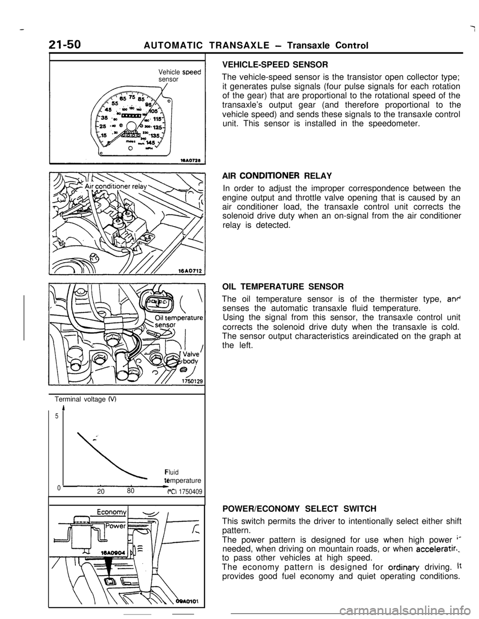
02080PCI 1750409VEHICLE-SPEED SENSOR
The vehicle-speed sensor is the transistor open collector type;
it generates pulse signals (four pulse signals for each rotation
of the gear) that are proportional to the rotational speed of the
transaxle’s output gear (and therefore proportional to the
vehicle speed) and sends these signals to the transaxle control
unit. This sensor is installed in the speedometer.
AIR CONDlTlONER RELAY
In order to adjust the improper correspondence between the
engine output and throttle valve opening that is caused by an
air conditioner load, the transaxle control unit corrects the
solenoid drive duty when an on-signal from the air conditioner
relay is detected.
OIL TEMPERATURE SENSOR
The oil temperature sensor is of the thermister type,
an+senses the automatic transaxle fluid temperature.
Using the signal from this sensor, the transaxle control unit
corrects the solenoid drive duty when the transaxle is cold.
The sensor output characteristics areindicated on the graph at
the left.
POWER/ECONOMY SELECT SWITCH
This switch permits the driver to intentionally select either shift
pattern.
The power pattern is designed for use when high power
‘*needed, when driving on mountain roads, or when acceleratirl,
to pass other vehicles at high speed.
The economy pattern is designed for ordinan/ driving.
ltprovides good fuel economy and quiet operating conditions.
Page 276 of 391

AUTOMATIC TRANSAXLE - Transaxle ControlSELF-DIAGNOStS SYSTEM
The transaxle control unit has self-diagnosis function.
Self-diagnosis codes can be read by connecting a voltmeter to the
diagnosis connector on the side of the junction block.
0: Ground
6%: ELC-MIT
Self-diagnosisThere are 25 diagnosis items, including those items
indicating normal conditions; a maximum of
10items can be stored in memory in the order that
they occur. The memory is supported by a power
supply directly connected to the battery so that it isretained even after the Ignition switch is turned to
the off position.
To clear the memory once an inspection has been
completed. keep negative
(-) terminal of the
battery disconnected for
10 seconds or longer.
r
No.
23
24
Output code
Display pattern
TDiagnosis itemRemarks
NormalAbnormal increases of throttle position
sensor output
Abnormal decrease of throttle position
sensor output
Poor adjustment of throttle position sen-
sorOpen circuit in oil temperature sensor
Once this occurs, output is re-
garded as 2.5 V.Once this occurs, output is re-
garded as 2.5 VOnce this occurs,
oil temperature isregarded as 80°C (176°F).
Page 371 of 391
-.-- ----_-
24-8HEATERS AND AIR CONDITIONING - Compressor
COMPRESSORR24GbCOMPRESSOR CONTROL
When both the blower switch and air conditioner
switch are ON, ON-OFF control of the magnetic
clutch is accomplished by the auto compressorcontrol unit. dual pressure switch, engine coolant
temperature switch and
MPI control unit.
Sub fusible
link
Dedicatedfuse
Air conditioner
compressor relayrOFfCompressor
magnetic clutch
q l
Fusible link
lgnitionsyhWqb 1Auto compressor control unit
ITT1 I
0 bIAirAir
inlettherm0
4sensorsensor
Engine coolanttemperature switch
Enginecontrol unit13A0167
Page 373 of 391

25-1
EMISSION
CONTROL SYSTEMSCONTENTS
RZSA---AIR-FUEL MIXTURE
RATIOCONTROL SYSTEM
. . . . . . . . . . . . . . . . . . . . . . . . .._.................9CATALYTIC CONVERTER
. . . . . . . . . . . . . . . . . .._............9CRANKCASE VENTlLATlON SYSTEM
. . . . . . . . . . . .10EVAPORATIVE EMISSION
CONTROL SYSTEM
: . . . . . . . . . . . . . . . . . . . . . . . . . . . . . . . ..-.........11Canister
. . . . . . . . . . . . . . . . . . . . . . . . . . . ..~...................._._...__..12
FuelCheck Valve. . . . . . . . . . . . . . . . . . . . . . . . . . . . . . . . . . . . .._.........14
FuelFiller Cap. . . . . . . . . . . . . . . . . . . . . . . . . . . . . . . . . . . . . . . . ..__....._..14Overfill Limiter (Two-way Valve)
_................... 14
Purge Control Solenoid Valve
. . . . . . . . . . . . . . . . . . . . . . . . . . . . . . . . . . . . . . . . . . . . . . . . . . . .13Purge Control Solenoid Valve
. . . . . . . . . . . _ . . . . . . . . . . . . . . . . . . . . . . . . . . . . . . . . . . . . . . . . . . . . . . . .13Purge Control Valve
. . . . . . . . . . . . . . . . . . . . . . . .13EXHAUST GAS RECIRCULATION
(EGR) SYSTEM. . . . . . . . . . . . . . . . . . . . . . . . . . . . . . . . . . . . . . . . . . . ..-......5
EGR Control Solenoid Valve . . . .8EGR Control Valve
..,.........................................7EGR Temperature Sensor
. . . . . . . .8Operation
. . . . . . . . . . . . . . . . . . . . . . . . . . . . . . . . . . . .6
Operation . . .._.........................._.._... _.5
Therm0 Valve. . . . . . . . . . . . . . . . . . . . . . . . . . . . . . . . .._.7GENERAL INFORMATION
. . . . . . . . . . . . . . . . . . . . . . . . . . . . . . . .2
Page 375 of 391

25-1
Eh/llSSlON
CONTROL SYSTEMS
rps*---
AIR-FUEL MIXTURE RATIO
_ . . . . . . . . . . . . . . . . . . . . . . . . . . . . . . . . . . .
CATALYTIC CONVERTER . . . . . . . . . . . . . . . . . . . . . . . . . . . . . . . .
._ _.__.____.
EVAPORATIVE EMISSION
: . . . . . . . . . . . . . . .._............. _ _.I.........
Canister . . . . . . . . . . . . . . . . . . . . . . . . . . . . . . . . . . . . \
. . . . . . . . . . . . . . . . . . . ..-..
Fuel Check Valve . . .._......._....._......__...._.__.............
Fuel Filler CapI.........._........................................
Overfill Limiter (Two-way Valve)_......._._.._._....
Purge Control Solenoid Valve
.._. _...
9
_..._............................................... 5
EGR Control Solenoid Valve . . . . 8
EGR Control Valve . . . . . . . . . . . . . . .._........................... 7
EGR Temperature Sensor . . . . . . . . 8
.._................ 6
Operation . . . . . . . .._._..................._..__.__. 5
Therm0 Valv e. . . . . . . . . . . . . . . . . . . . . . . . . . . . . . . . .._. 7
GENERAL INFORMATIO N. . . . . . . . . . . . . . . . . . . . . . . . . . . . . . . . 2
Page 377 of 391
EMISSION CONTROL SYSTEMS - General Information25-3
INon-Turbo for California
Q
&i,& Canister<; /’Aircleaner\
hrinlet &j=-=&=p==~
oxz pJCatalytic converterEGR temperature sensor
ON Purge control
solenoid
valve
EGR controlsolenoid valve
Turbo for FederalAir
cleper
E
-II 11-l I-d-h I
-u’Catalytic a3nverter
in
Purge controlsolenoid
valve
6EM0260