1990 MITSUBISHI ECLIPSE sensor
[x] Cancel search: sensorPage 172 of 391

-.
14-60FUEL SYSTEM - Auto-cruise Control System
SYSTEM BLOCK DIAGRAM
---
f?,: 0,
,’
vi
switch cpJT>
Auto-cruise control switch. MAIN switchl SET (COAST) switchl RESUME (ACCEL) switc
I
Intermedi-ate linkActuator
mechanismCOMPONENT PARTS AND FUNCTION OUTLINE
Component part
Vehicle speed sensor
6\uto-cruise control unit
Function
Converts vehicle speed to pulse,
Receives signals from sensor and control switches; microcomputercontrols all auto-cruise control functions
ActuatorRegulates the throttle valve to the set opening by signals from the
auto-cruise control unit
Control switchMAIN switch
Switch for auto-cruise control power supply
SET
(COAST) switchControls auto-cruise control functions by SET (COAST) and
1 RESUME (ACCELIRESUME (ACCEL) switch
Cancel switch
Stop light switchClutch switch
Inhibitor switch CA/T>
Accelerator switch
During constant speed driving, the accelerator pedal is inactive and
the accelerator switch is turned ON.
Therefore, OFF signal is output from the auto-cruise control unitto the ELC
4A/T control unit during constant speed driving only.
4-I-Ed automatic transaxle control unitControls overdrive ON and OFF based on overdrive ON andOFF signals from the auto-cruise control unit for the auto-cruise
controlAuto-cruise indicator lightThis indicator light illuminates to indicate that the vehicle is
traveling in the auto-cruise mode.
Diagnosis connectorBY connecting a voltmeter control unit diagnosis and input-check
codes can be read out (for details, refer to P. 14-69).
Page 173 of 391

F
FUEL SYSTEM -Auto-cruise Control System'l4-61
AUTOCRUISE CONTROL UNIT
Je auto-cruise control unit incorporates a micro-computer which provides the set coast, resume,
acceleration, cancel, low-speed limitation,
high-speed limitation, overdrive OFF control, and
auto-
matic cancellation functions. The microcomputer
inputs signals from the vehicle speed sensor and
the switches, and outputs Control signals to the
actuator’s DC motor, the electromagnetic clutch,and the automatic
.transaxle (4 A/T) control unit in
accordance with the programming (software) of themicrocomputer.
CONTROL LOGIC BLOCK DIAGRAM
--
Auto-cruise control UnitIgnitionswitcha.-.
I
Input interface circuit
piz7q.f~~
I
L
Micro-
computer
jutput interface circuitIr--lI----
--7I IActuatorI
Electromagnetic
clutch coil
OD-OFF out-
put circuit
NC: Normally closed
Page 182 of 391

14-70
-_FUEL SYSTEM
- Auto-cruise Control System
Display when vehicle speed is approximately
20 km/h (12 mph) or higher, or before the
auto-cruise conrrol system is set
12AolO
NOTE1. Codes indicated by thel symbol are displayed, if
tt-conditions are satisfied, even if the system is normal.
I,.either case, the system is normal if it can be reset.
2. Diagnosis codes are displayed when, after cancellation of
the auto-cruise control system, the vehicle speed de-
creases to less than approximately 20 km/h (12 mph), and
are erased by switching OFF the ignition switch or the
MAIN switch. After the diagnosis codes in the memory are
erased, if (when the power supply of the electronic control
unit is switched ON once again) the power supply of the
electronic control unit is normal, continuous ON/OFF
signals will be displayed at
O.&second intervals, regardless
of whether the system condition is normal or not. (Refer to
the illustration at the left.)
INPUT-CHECK FUNCTION
The input-check function allows you to check if the input signal
is normal when a cruise control failure occurs, including the
situation where the cruise control cannot be set.
(1) Connect a voltmeter to the diagnosis connector of the
junction block.
(2) Operate the SET and RESUME switches simultaneously.
(3) Turn ON the ignition switch; the input check can now be
carried out. Perform the corresponding input operations to
read the output codes.
Output codes
Display patternsInput
operationCheck resultst
y- 0.5sec.
n
SET switch ONSET switch circuitis normal.RESUME switch circuit
is normal.
Each cancel switch ON1. Stop light switch
(brake pedal depressed)2. Clutch switch
(clutch pedal depressed)3. Inhibitor switch ON
(shift lever to “N” position)Each cancel switch
circuit is normal.
Driving at approx. 40 km/h
(25mph) or higherWhen both No. 24 andNo. 25 can be con-firmed, vehicle speed
sensor circuit is
normal.Driving at less than approx. 40
km/h (25
mph). or stopped
NOTE1.If two or more input operations are performed at the same time and the microcomputer receives the corresponding
signals, their output codes are indicated repeatedly in code number order as long as the corresponding signals are
2.input.If the input operation is canceled while the output code is being indicated, the code continued to be indicated until it
completes a display cycle. If the code does not disappear, the switch or harness is probably defective.
Page 187 of 391

_-.-, ._ u .-, 4. ::; bt-i 3,. F-7__ . ._,_ _ ” -- --.-....
FUEL SYSTEM- Auto-cruise Control System14-75INTERMEDIATE LINKS
Intermediate
iink A(accelerator pedal side)Accelerator cable
A
(accelerator pedal side)
03AO224During Auto-cruise Control Driving
The rotation of the selector causes intermediate link
B to turn
which opens and closes the throttle valve. However, intermedi-
ate link A is not operated and accelerator cable A does not
move, so the accelerator pedal remains stationary in its original
position.During Normal Driving
When the accelerator pedal is operated, the rotation of
intermediate link A, which is connected to accelerator cable A
(accelerator pedal side), causes intermediate link
B to turn, and
accelerator cable
B, which is connected to intermediate link B,then opens and closes the throttle valve.
N
0
s -?s
*=Auto-cruise
control unit
13AOO62Vehicle speed
sensor07Aml
VEHICLE SPEED SENSORThe vehicle speed sensor functions to send pulse signals
[which are proportional to the rotation speed (vehicle speed) of
the transaxle’s output gear] to the control unit. The vehicle
speed sensor is installed within the speedometer.
The vehicle speed sensor is the reed switch type; it generates
four pulse signals for each rotation of the output gear. This
sensor is also used in common for other electronic control
systems.
Page 265 of 391

AUTOMATIC TRANSAXLE - Transaxle Mechanism21-41
YWNSAXLE CONTROL
GENERAL DESCRIPTION
Hydraulic-pressure
control mechanism
Electronic
control-
r
1Pulse oenerator A
DanI
iI11. . . .
control solenola
valve
Pressure controlsolenoid valve
Shift cOntrOisolenoid valve
r-7i1
Diagnosis
connector
Ft2iFu~The transaxle control system is composed of
various type of sensors, the transaxle control
unit.and the hydraulic control device, and it functions for
(1) damper clutch control, (2) shift pattern
Control.and (3) hydraulic control, during shifting.
%, In other words, data signals received
fromthe
.$ various sensors enable the driving conditions to beJ-
sj.q’74:i.&f’detected, and, based upon the preset damper clutch
engaging range, shift pattern and hydraulic pattern,
the damper clutch control solenoid valve, the shift
Control solenoid valve and the pressure control
solenoid valve are driven, which assures that a good“feeling” during shifting is maintained.
Page 266 of 391

21-42AUTOMATIC TRANSAXLE - Transaxle Control
ELECTRONIC CONTROL DEVICE
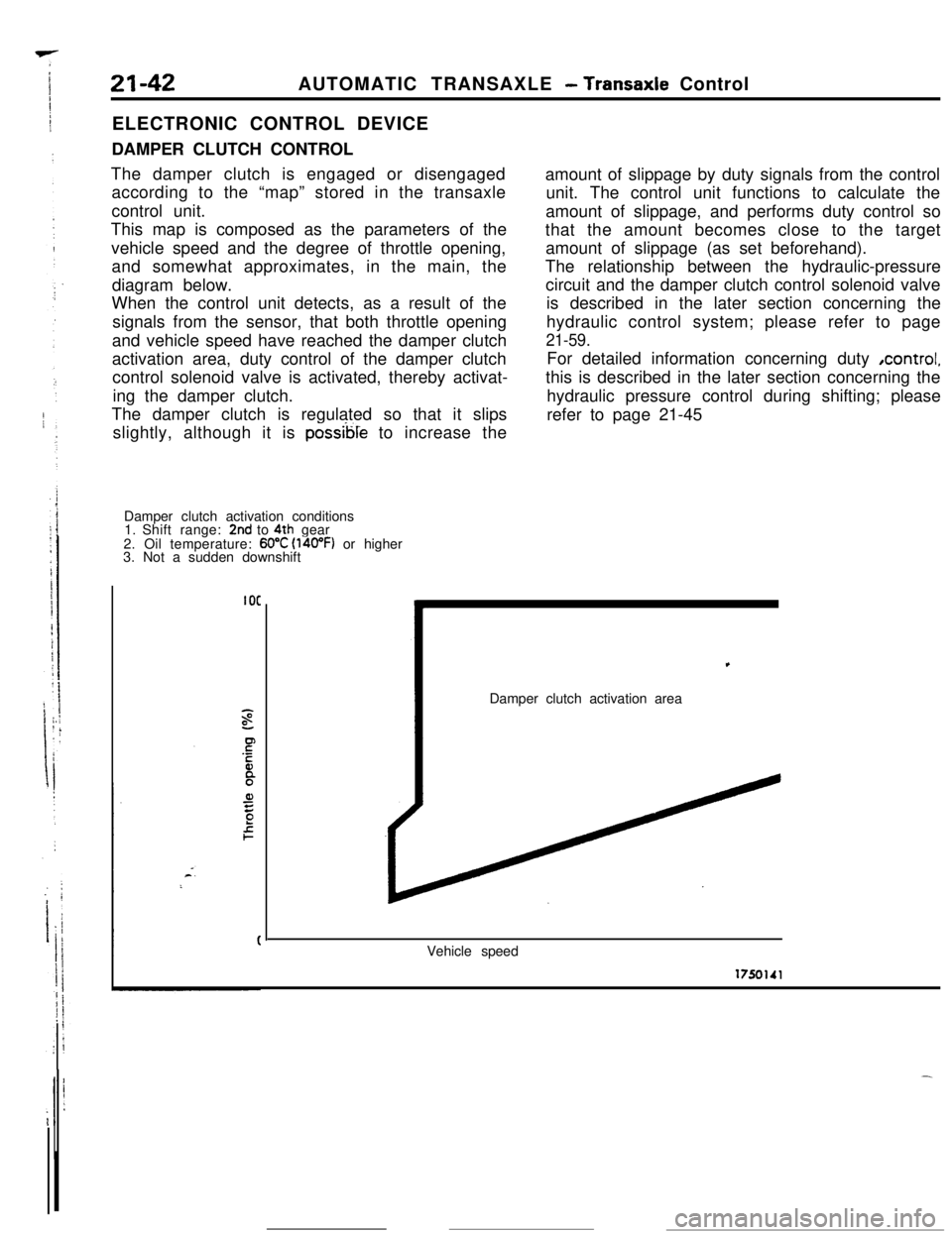
DAMPER CLUTCH CONTROL
The damper clutch is engaged or disengaged
according to the “map” stored in the transaxle
control unit.
This map is composed as the parameters of the
vehicle speed and the degree of throttle opening,
and somewhat approximates, in the main, the
diagram below.
When the control unit detects, as a result of the
signals from the sensor, that both throttle opening
and vehicle speed have reached the damper clutch
activation area, duty control of the damper clutch
control solenoid valve is activated, thereby activat-
ing the damper clutch.
The damper clutch is regulated so that it slips
slightly, although it is
possible to increase the
Damper clutch activation conditions
1. Shift range:
2nd to 4th gear
2. Oil temperature: 60°C (l4oOF) or higher
3. Not a sudden downshift
IOCamount of slippage by duty signals from the control
unit. The control unit functions to calculate the
amount of slippage, and performs duty control so
that the amount becomes close to the target
amount of slippage (as set beforehand).
The relationship between the hydraulic-pressure
circuit and the damper clutch control solenoid valve
is described in the later section concerning the
hydraulic control system; please refer to page
21-59.For detailed information concerning duty ,control,
this is described in the later section concerning the
hydraulic pressure control during shifting; please
refer to page 21-45,
Damper clutch activation area
Vehicle speed
Page 267 of 391

AUTOMATIC TRANSAXLE - Transaxle Control21-43
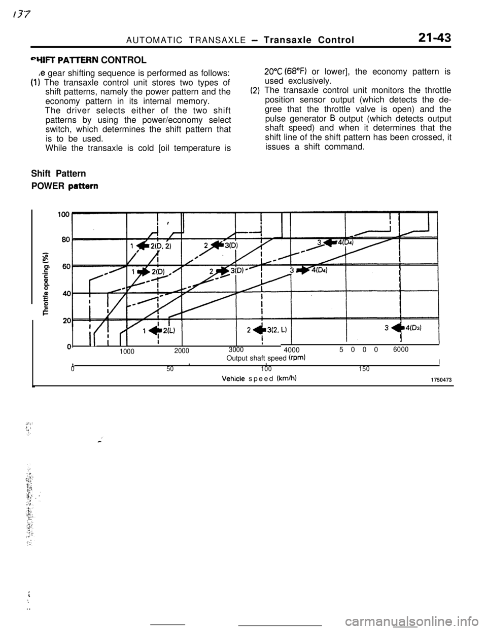
“YIR PAllERN CONTROL
,e gear shifting sequence is performed as follows:
(1) The transaxle control unit stores two types of
shift patterns, namely the power pattern and the
economy pattern in its internal memory.
The driver selects either of the two shift
patterns by using the power/economy select
switch, which determines the shift pattern that
is to be used.
While the transaxle is cold [oil temperature is
(2)
Shift Pattern
POWER
pattern
20°C (68°F) or lower], the economy pattern is
used exclusively.
The transaxle control unit monitors the throttle
position sensor output (which detects the de-
gree that the throttle valve is open) and the
pulse generator
B output (which detects output
shaft speed) and when it determines that the
shift line of the shift pattern has been crossed, it
issues a shift command.
i
II I (I
I -L\LI1- --‘-0
II
0I
100020003000
II400050006000
10Output shaft speed (rpmlIII50100150Vehicle speed
(km/h)1750473
rL;. .
Page 269 of 391

‘4) Once the operation is step (2) is completed, the
hydraulic control device functions by hydraulic
pressure force to change the state of the
clutches and brakes to accomplish the gear
shifting. To minimize the shock that would
otherwise be produced during gear shifting,
hydraulic pressure is controlled during the gear
shifting period by the “duty control” of the
pressure control solenoid valve. The duty control
is explained later.
‘HYDRAULIC PRESSURE CONTROL DURING
SHFIING(1) The hydraulic pressure that functions during
gear shifting to engage the clutches and apply
the brakes is regulated by the pressure control
valve, The hydraulic pressure that works on the
pressure control valve is further regulated by the
pressure control solenoid valve which functions
under the control of the transaxle control unit.
The transaxle control unit controls the solenoid
valve through the duty control, thus providing
appropriate regulation of the hydraulic pressure.
(2)
(3)
(4)The transaxle control unit decides the timing of
the gear shifting period (during which ‘it per-
forms hydraulic pressure control for gear shift-
ing) according to the change in the kickdown
drum rotating speed that it detects. The unit
identifies the time just before the kickdown
brake is applied and uses that as the timing for
initiating control of the hydraulic pressure which
is to be applied to the kickdown brake.
When the transaxle is cold, the fluid viscosity is
high, causing slower oil pressure response. in
such conditions, the transaxle control unit pro-
vides a correction for the oil pressure by
changing the control duty of the pressure control
solenoid valve.
This control is performed when the fluid temper-
atures as indicated by the oil temperature
sensor is lower than
60°C (140°F).After the engine has been started and the
vehicle is inmotion, the transaxle
continues torefine its performance
est possiblegear shifting.control unit
for smooth-
tHFigure B
- Duty(%)
17500661750067
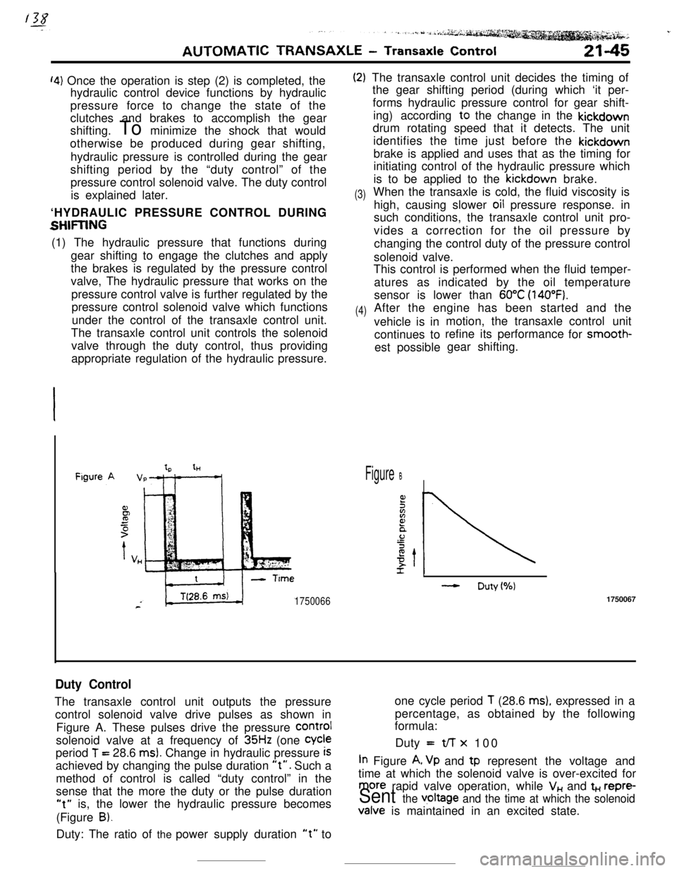
Duty ControlThe transaxle control unit outputs the pressureone cycle period
T (28.6 ms), expressed in a
control solenoid valve drive pulses as shown inpercentage, as obtained by the following
formula:
Figure A. These pulses drive the pressure
COrmIsolenoid valve at a frequency of
35Hz (one Cycleperiod
T = 28.6 ms). Change in hydraulic pressure iSDuty =t/-r x 100
achieved by changing the pulse duration
“t”. Such aIn Figure A, Vp and tp represent the voltage and
method of control is called “duty control” in thetime at which the solenoid valve is over-excited for
sense that the more the duty or the pulse duration
more rapid valve operation, while V,, and t+., repre-
“t” is, the lower the hydraulic pressure becomesSent the v,oltage and the time at which the solenoid(Figure
B).Valve is maintained in an excited state.
Duty: The ratio of the power supply duration
“t” to