Page 128 of 391

14-16FUEL SYSTEM - Sensors
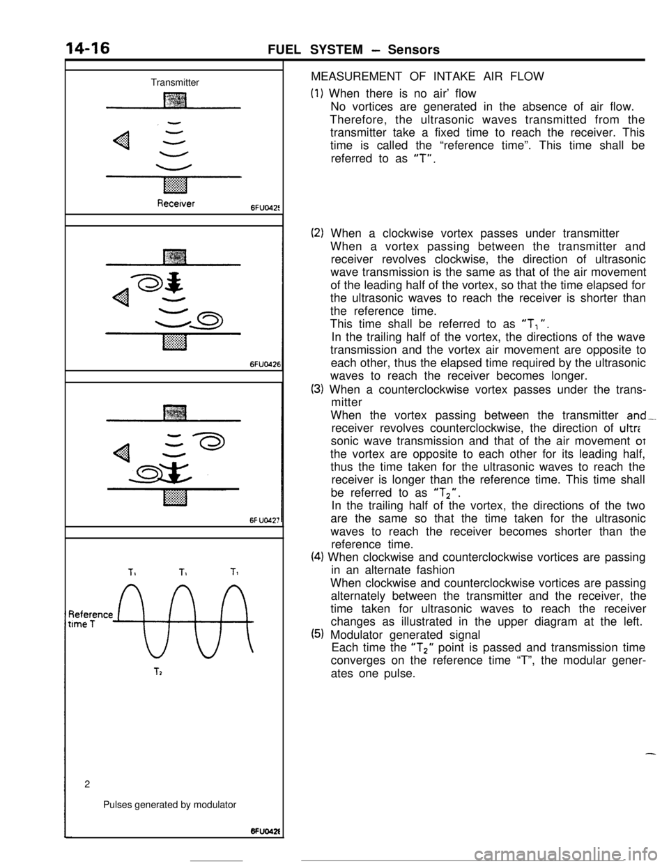
TransmitterMEASUREMENT OF INTAKE AIR FLOW
(1) When there is no air’ flow
No vortices are generated in the absence of air flow.
Therefore, the ultrasonic waves transmitted from the
transmitter take a fixed time to reach the receiver. This
time is called the “reference time”. This time shall be
referred to as
“T”.
Recetver6FUo42!
6FUO426
6f UO42;
TIT1Tl
~tee;ence
9%
T22
Pulses generated by modulator
(2) When a clockwise vortex passes under transmitter
When a vortex passing between the transmitter and
receiver revolves clockwise, the direction of ultrasonic
wave transmission is the same as that of the air movement
of the leading half of the vortex, so that the time elapsed for
the ultrasonic waves to reach the receiver is shorter than
the reference time.
This time shall be referred to as
“T, “.
In the trailing half of the vortex, the directions of the wave
transmission and the vortex air movement are opposite to
each other, thus the elapsed time required by the ultrasonic
waves to reach the receiver becomes longer.
(3) When a counterclockwise vortex passes under the trans-
mitter
When the vortex passing between the transmitter
and-.receiver revolves counterclockwise, the direction of ultr:
sonic wave transmission and that of the air movement
OTthe vortex are opposite to each other for its leading half,
thus the time taken for the ultrasonic waves to reach the
receiver is longer than the reference time. This time shall
be referred to as
“Tz”.In the trailing half of the vortex, the directions of the two
are the same so that the time taken for the ultrasonic
waves to reach the receiver becomes shorter than the
reference time.
(4) When clockwise and counterclockwise vortices are passing
in an alternate fashion
When clockwise and counterclockwise vortices are passing
alternately between the transmitter and the receiver, the
time taken for ultrasonic waves to reach the receiver
changes as illustrated in the upper diagram at the left.
(5) Modulator generated signal
Each time the “T2” point is passed and transmission time
converges on the reference time “T”, the modular gener-
ates one pulse.
-
Page 129 of 391

FUEL SYSTEM - SensorsWhen more air
is drawnT1
Pulses generated by modulatorWhen
less air is drawn6FUO42
TI
IPulses generated by modulator6FuWAs a result, when more air is drawn, the modulator
generates more pulses, and when less air is drawn, it
generates less pulses.
The air flow sensor measures the intake air flow based on
this principle.
INTAKE AIR TEMPERATURE SENSOR
IIntake airtemperature sensor
Intake airAir bypass pipesEC654
Intake airtemperature
sensor
s-v
r .==
II
fi ;=---
Engine control unit
6 FUOOSL-20
I410 (32)20 I6913
Intake air temoerature
Intake air temperature “C (‘Fl 1624581621008
e intake air temperature sensor mounted at theBased on the sensor output voltage. the engine
.
..Jstrated location on the air flow sensor is acontrol unit determines the intake air temperature
thermistor which is a kind of resistor whose and corrects the amount of fuel to be injected
resistance changes as a function of the intake air
accordingly.temperature.Curves indicating the sensor characteristics are
shown above.
Page 130 of 391

14-18FUEL SYSTEM - Sensors
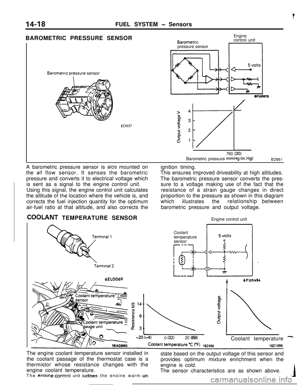
tBAROMETRIC PRESSURE SENSOR
Barometnc rxessure sensor
EC1537
Barometncpressure sensor
Enginecontrol unit
1OFUO576
/
760 (30)Barometric pressure mmHg
(in.Hg)EC1551A barometric pressure sensor is
alas mounted on
the
aif flow sensor. It senses the barometric
pressure and converts it to electrical voltage which
is sent as a signal to the engine control unit.
Using this signal, the engine control unit calculates
the altitude
of.the location where the vehicle is, and
corrects the fuel injection quantity for the optimum
air-fuel ratio at that altitude, and also corrects the
COOLANT TEMPERATURE SENSOR
Terminal 26EL0069ignition timing.
This ensures improved driveability at high altitudes.
The barometric pressure sensor converts the pres-
sure to a voltage making use of the fact that the
resistance of a strain gauge changes in direct
proportion to the pressure as shown in this diagram
which
illustratestherelationship between
barometric pressure and output voltage.
Engine control unit
Coolanttemperature
sensor
-a
Tg-I
h-esI
*
5 volts
LizIdr
tSFUOLSL
L0 (32120 (68)Coolant temperature -The engine coolant temperature sensor installed in
the coolant passage of the thermostat case is a
thermistor whose resistance changes with the
engine coolant temperature.
The
annine control unit iudoes the enoine warm UDstate based on the output voltage of this sensor and
provides optimum mixture enrichment when the
engine is cold.
The sensor characteristics are as shown above..:I
Page 131 of 391

FUEL SYSTEM - Sensors
THROTTLE POSITION SENSOR
ThrottleThrottle
posItIon
sensorposltion sensor
,_Il-
Engine control unit
1
6FU0782
Throttle opening deg.
Full o IO 20 30 4070 0002closeFullopenThe throttle position sensor is a variable resistor
whose movable contact rotates
coaxially with the
cattle valve shaft, thus sensing the throttle valve
.
,,ening.As the throttle valve shaft rotates, the sensor outputgenerates, the engine control unit detects the
throttle valve opening and determines the engine
operation mode (acceleration or deceleration).
The relationship between the throttle opening and
the output voltage is as shown above.
voltage changes. Based on the signal the sensor
IDLE POSITION SWITCH
Idle positionswitchTermtnal
7FUO20Throttle body
Idle positlonswitch
I6Fw497I
rle idle position switch is a contact type switch thatinto the throttle bore when the valve is fully closed.
detects operation of the accelerator pedal. ThisThis setting has been performed accurately at the
switch also serves as the throttle stop screw, whichfactory; the lock nut should not be loosened, or the
has been set at the minimum opening of the throttleidle position switch be moved inadvertently.
‘valve so as to prevent the throttle valve from biting_
Page 132 of 391

FUEL SYSTEM - Sensors
CRANK ANGLE SENSOR
II
DiscSensor
The crank angle sensor is mounted on the cylinder
head and is directly coupled to the intake camshaft.The crank angle sensor consists of a disc -and a
sensor unit.
Mu0499Slit for
crank anglesensor
Photo diode
LED
The disc, made of metal, has four slits located 90 degrees aparton its periphery and two slits located 180 degrees apart inward
of the four slits.
-The inner slits are used by the top dead center sensor
th,detects the top dead center of the No.
1 and No. 4 cylinders,
and the outer four slits are used by the crank angle sensor that
detects the crank angle. The disc is positioned on the sensor
shaft and rotates as a unit with it, being turned by the intake
camshaft.The sensor unit has two
LEDs and two photo diodes, used’to
detect the crank angle sensor slits and the top dead center
sensor slits.
The disc rotates between the
LEDs and the photo diodes. Each
time a slit comes between a LED and photo diode pair, the light
emitted by the LED reaches the photo diode by passing
through the slit.
Sensor unit
I I1
Power supply
I
Engine control untt
r
Crank angleslgnal
Page 133 of 391

FUEL SYSTEM - Sensors14-21When exposed to light, the photo diode conducts
urrent in a direction opposite to an ordinary diode.
.s a result, current flows in the direction indicated
by the arrow and dotted line and a voltage (5 volts) isapplied to the comparator of the sensor unit so that
the terminal voltage of the engine control unit
becomes 5 volts. When the disc rotates further andthe slit moves beyond the space between the
LED/photo diode pair, the light can no longer reach
the photo diode, thus the current indicated by the
dotted line ceases to flow and the terminal voltage
of the engine control unit becomes 0 volt.
tn this
way, pulse signals are sent to the engine control
unit from the sensor unit.
OXYGEN SENSOR
k
1 ~~~~t13ate~ousingCoverLead wiresConnectorHeater
Enginecontrol unit6FUlOO5
- Oxygen‘-serisor
The oxygen sensor is mounted at the outlet of the exhaust
manifold or the turbocharger. The sensor, which uses an
oxygen concentration cell having a, solid electrolyte, has such
characteristics that its output voltage changes sharply in the
vicinity of the stoichiometric air/fuel ratio.
The sensor makes use of this characteristic to detect oxygen
concentration in the exhaust gas and feeds back the signal to
the engine control unit, which then decides if the air/fuel ratio is
rich or iean relative to the stoichiometric ratio.
Based on this decision, the air/fuel ratio is feedback-controlled
to achieve the stoichiometric ratio at which the catalytic
converter operates most effectively.
In addition, because this oxygen sensor incorporates a heater,
the response of the sensor is good even if the temperature of
the exhaust gas is low, and, as a result, feedback control of the
air/fuel ratio is possible for a short time after the engine is
started.
Stoichiometric air/fuel ratlo
r3
Lean
Air/fuel ratioEC1007
Page 134 of 391
14-22FUEL SYSTEM - Sensors
VEHICLE SPEED SENSOR
L
Vehicle speessensor
Vehicle speed sensor
10*0051speed sensorEngine control unit
6FlJO604
1 revoluttonI
‘r’471
16245
7
B
1Vehicle speed km/h (mph)The vehicle speed sensor is a reed switch type sensor and is
installed in the speedometer. It converts the transmission
speedometer driven gear revolutions (vehicle speed) to
ptsignals and sends them to the engine control unit.
The sensor generates four pulse signals for each rotation of the
speedometer driven gear.
5Therefore, the sensor output frequency increases in proportion
to the vehicle speed as shown at the left.
-
Page 135 of 391
‘7JFUEL SYSTEM
- Sensors14-23AIR CONDITIONER SWITCH
Batten/
-31 .,Air conditioner unitlSAO735‘Air conditioner
control unitI”.._. ,voltage
Dual pressureswitch
-f@ -//Q.j
/
Coolanttemperature6FU1148
switch
Engine control unit
3Air conditioner
This switch sends the air conditioner ON/OFF signal
to the engine control unit.
When the air conditioner is turned on and the enginecontrol unit receives the ON
signal from the switch,
it commands the idle speed control servo
toincrease the idle speed to the preset rpm. Thus
engine rpm loss due to air conditioner operation
while the engine is idling is prevented and smooth
idling operation is ensured.