Page 786 of 1273
23-80AUTOMATIC TRANSAXLE - Troubleshooting
E.L.C. 4-SPEED AUTOMATIC TRANSAXLE CONTROL COMPONENT LAYOUT,
NameSymbol Name
Data link connector
FPulse generator A
4 A/T control module
HPulse generator 6
MFI control moduleISolenoid valve
Oil temperature sensor
DThrottle position sensor
Power (PWR)/Economy
(ECO) switch
GVehicle-speed sensor
NOTEThe “Name” column is arranged in alphabetrcal order.
C and D are built into the transaxle.
Symbol
A
A
C
B
E
FWD . . . From 1993 model
TSB Revision
Page 788 of 1273
23-82AUTOMATIC TRANSAXLE - Service Adjustment Procedures
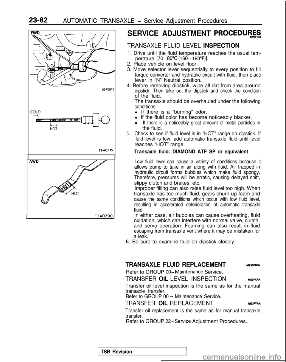
HOTTFA0715
AWD
LT FA0700J
SERVICE ADJUSTMENT PROCEDUR&g
TRANSAXLE FLUID LEVEL INSPECTION
1. Drive until the fluid temperature reaches the usual tem-
perature [70-80°C
(160- 18O”F)I.
2. Place vehicle on level floor.
3. Move selector lever sequentially to every position to fill
torque converter and hydraulic circuit with fluid, then place
lever in “N” Neutral position.
4. Before removing dipstick, wipe all dirt from area around
dipstick. Then take out the dipstick and check the condition
of the fluid.
The transaxle should be overhauled under the following
conditions.
l If there is a “burning” odor.
l If the fluid color has become noticeably blacker.
l
If there is a noticeably great amount of metal particles in
the fluid.
5.Check to see if fluid level is in “HOT” range on dipstick. If
fluid level is low, add automatic transaxle fluid until level
reaches “HOT” range.
Transaxle fluid: DIAMOND ATF SP or equivalent
Low fluid level can cause a variety of conditions because it
allows pump to take in air along with fluid. Air trapped in hydraulic circuit forms bubbles which make fluid spongy.
Therefore, pressures will be erratic, causing delayed shift,
slippy clutch and brakes, etc.
Improper filling can also raise fluid level too high. When
transaxle has too much fluid, gears churn up foam and
cause the same conditions which occur with low fluid level, resulting in accelerated deterioration of automatic transaxle
fluid.
In either case, air bubbles can cause overheating, fluid
oxidation, which can interfere with normal valve, clutch,
and servo operation. Foaming can also result in fluid
escaping from transaxle vent where it may be mistaken for
a leak.
6. Be sure to examine fluid on dipstick closely.
TRANSAXLE FLUID REPLACEMENTM23FcsGa
Refer to GROUP 00-Maintenance
Service.
TRANSFER OIL LEVEL INSPECTIONMm=xM
Transfer oil level inspection is the same as for the manual
transaxle transfer.
Refer to GROUP 00
- Maintenance Service.
TRANSFER OIL REPLACEMENTM23FYAA
Transfer oil replacement is the same as for manual transaxle
transfer.
Refer to GROUP 22-Service
Adjustment Procedures.
TSB Revision
Page 794 of 1273
23-88AUTOMATIC TRANSAXLE - Service Adjustment Procedures
8. Engage the special tool (outer) on the locking nut.
Rotating the outer cyliner clockwise and the inner cylinder
counterclockwise, unlock the locking nut and special tool
(inner).
Caution
When unlocking the lock, apply equal force to both
tools.
WD . . . Up to 1992 model -
&@~o-&q
9. Tighten the locking nut by hand until the locking nut
contacts the piston. Then, using the torque wrench, tighten
to the specified torque.
Locking nut: 25-32
Nm (18-23 ft.lbs.)
Caution
If it is rapidly tightened with the socket wrench or
torque wrench, the lock nut and adjusting rod may
rotate together.
10. Remove the special tool which fastens the piston.
Attach the plug to the outlet of the low reverse pressure.
LINE PRESSURE ADJUSTMENT
1. Drain out the automatic transaxle fluid.
2. Remove the oil pan.
3. Remove the oil filter.
4. Remove the oil-temperature sensor.
J
1 TSB Revision
M23F9A9
Page 797 of 1273
AUTOMATIC TRANSAXLE -Service Adjustment Procedures23-91
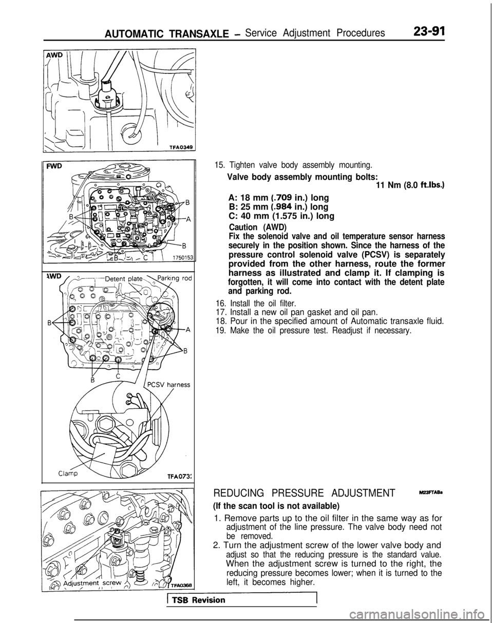
15. Tighten valve body assembly mounting.
Valve body assembly mounting bolts:11 Nm (8.0 ftlbs.)
A: 18 mm (.709
in.) long
B: 25 mm (.984
in.) long
C: 40 mm (1.575 in.) long
Caution (AWD)
Fix the solenoid valve and oil temperature sensor harness
securely in the position shown. Since the harness of the
pressure control solenoid valve (PCSV) is separately
provided from the other harness, route the former
harness as illustrated and clamp it. If clamping is
forgotten, it will come into contact with the detent plate and parking rod.
16. Install the oil filter.
17. Install a new oil pan gasket and oil pan.
18. Pour in the specified amount of Automatic transaxle fluid.
19. Make the oil pressure test. Readjust if necessary.
REDUCING PRESSURE ADJUSTMENTMZ3FTAb
(If the scan tool is not available)
1. Remove parts up to the oil filter in the same way as for
adjustment of the line pressure. The valve body need not
be removed.
2. Turn the adjustment screw of the lower valve body and
adjust so that the reducing pressure is the standard value.
When the adjustment screw is turned to the right, the
reducing pressure becomes lower; when it is turned to the
left, it becomes higher.
Page 798 of 1273
23-92AUTOMATIC TRANSAXLE - Service Adjustment Procedures
NOTE
When adjusting the reducing pressure, aim for the center
value (425 kPa, 60 psi) of the standard value allowance.
Standard value: 415-435
kPa (59-62 psi)
Oil pressure change for each turn of adjustment screw: 22
kPa (3.1 psi) . . . FWD (Up to MODEL 1990)
45
kPa (6.4 psi) . . . FWD (From MODEL 1990.5, AWD)
3. Install the oil filter and oil pan in the same way as for adjustment of the line pressure.
4. Make the oil pressure test. Readjust if necessary.
(If the scan tool is used)
1. Using the scan tool, forcibly drive the pressure control
solenoid valve at 50% duty, and measure the kick-down
brake apply pressure.
If the kick-down brake apply pressure does not exist within
the standard value width, adjust the pressure with the
reducing pressure adjustment screw.
Standard value: 275 + 10 kPa (39 + 1 psi)
Oil pressure change for each turn of adjustment screw:
25 kPa (3.6 psi) FWD (Up to MODEL 1990)
22
kPa (3.1 psi) FWD (From MODEL 1990.5), AWD
2. Check to be sure that the reducing pressure (after the
adjustment is completed) is within the range of 360-480
kPa (51 -68 psi.).
Caution
This adjustment should be made at an oil
temperature
of 70- 80°C
(160- 180°F).
If the adjustment is made at a temperature that is too
high, the line pressure will drop during idling, with the
result that it might not be possible to make the correct
adjustment.
I / Oii
seal09K561
THROTTLE-POSITION SENSOR ADJUSTMEF&
Refer to GROUP 13-On-Vehicle Inspection of MFI Compo-
nents.
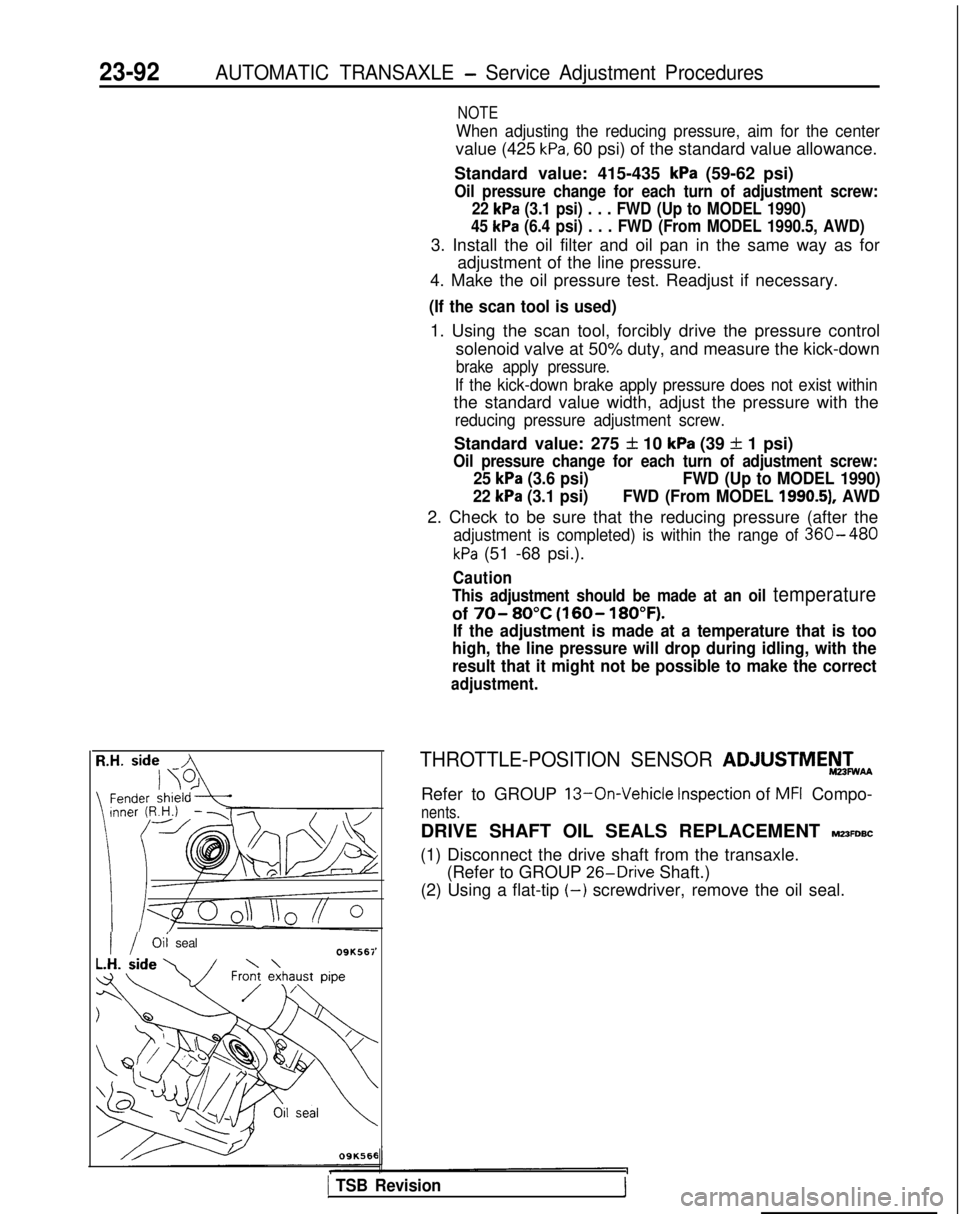
DRIVE SHAFT OIL SEALS REPLACEMENT MZ3FDBC
(1) Disconnect the drive shaft from the transaxle. (Refer to GROUP 26-Drive
Shaft.)
(2) Using a flat-tip
(-) screwdriver, remove the oil seal.
1 TSB Revision1
Page 807 of 1273
AUTOMATIC TRANSAXLE - Transaxle Assembly
TRANSAXLE ASSEMBLY
REMOVAL AND INSTALLATION
23-101
mz3u-
Pre-removal and Post-installation Op-eration@Draining and Supplying of the TransaxleFluid(Refer to GROUP 00-Maintenance Ser-vice.)*Removal and Installation of the Batteryand Battery TrayofRemoval and Installation of the Air Clean-
fRrefer to GROUP 15-Air
Cleaner.)*Removal and Installation of the Air Com-pressor(Vehicles with ACTIVE-ECS)(Refer to GROUP 33B-Air Compressor.)
cl989 models>27-34 Nm20-25ft.lbs.I360-80Nm43-58ft.lbS.60-80Nm43-58ft.lbs.
43-55 Nm
IO-12 Nm7.2-8.7 ft.lbs.
27-34 Nm20-25 ft.lbs.
30-35 km
b22-25 ft.lbs.
Iii ’30-35 Nm
22-25 ft.lbs.
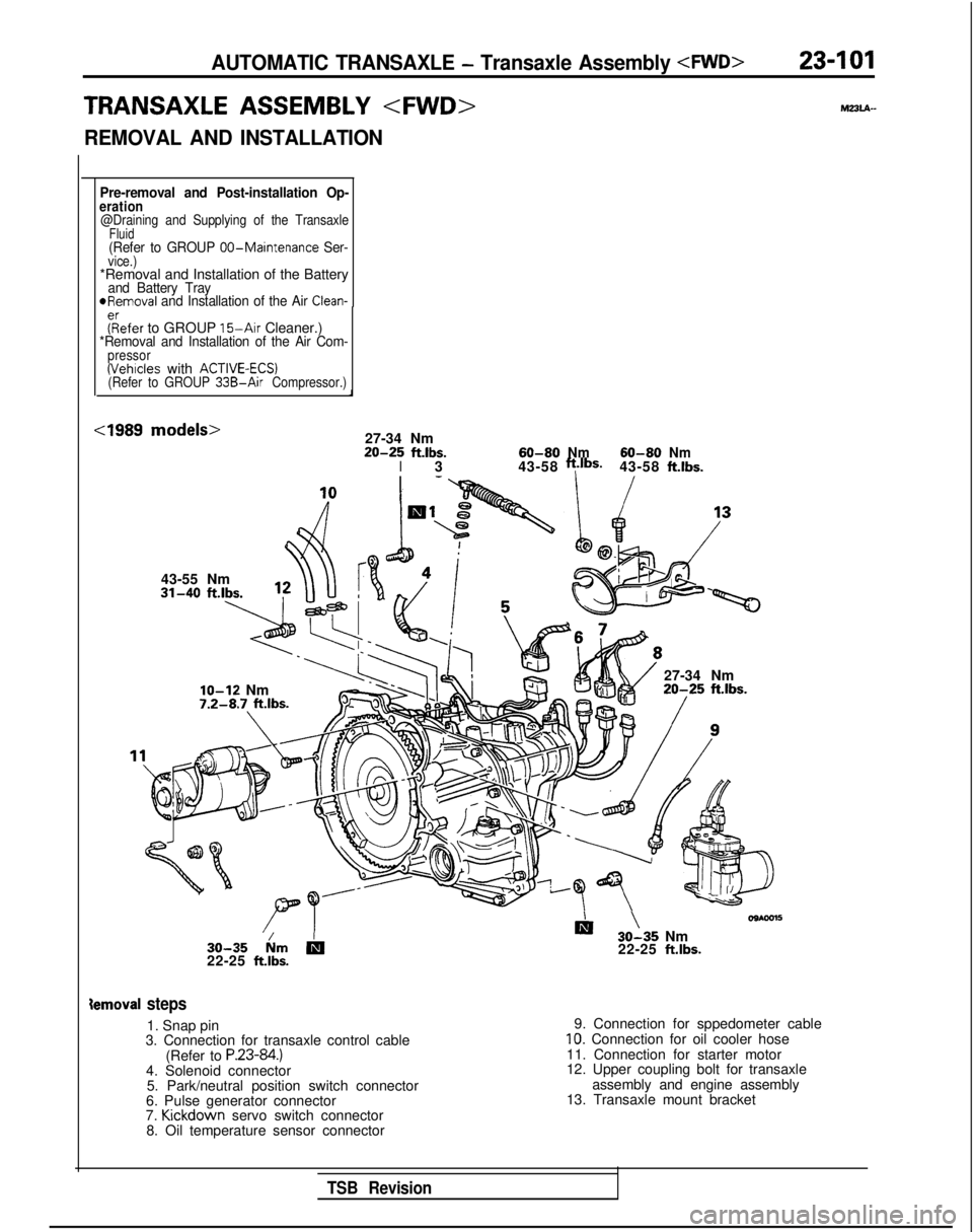
ternoval steps
1. Snap pin
3. Connection for transaxle control cable
(Refer to
P.23-84.)4. Solenoid connector5. Park/neutral position switch connector
6. Pulse generator connector
7. Kickdown
servo switch connector
8. Oil temperature sensor connector 9. Connection for sppedometer cable
10. Connection for oil cooler hose
11. Connection for starter motor
12. Upper coupling bolt for transaxle assembly and engine assembly
13. Transaxle mount bracket
TSB Revision
Page 808 of 1273
23-102AUTOMATIC TRANSAXLE - Transaxle Assemblv
27-34 Nm220-25 ftlbs.
\
43-55 Nm
60-80 Nm
60-80 Nm
/43-58 ftlbs.
43-58
ftlbs.
/\ /\ 930-35 NmDm 30-35 N
m
22-25
ftlbs.22-25 ft.lbs.
Iemoval steps
2. Adjusting nut
3. Connection for transaxle control cable (Refer to
P.23-85.)4. Solenoid connector
5. Park/neutral position switch connector
6. Pulse generator connector
7. Kickdown
servo switch connector
8. Oil temperature sensor connector
9. Connection for speedometer cable
10. Connection for oil cooler hose
11. Connection for starter motor
12. Upper coupling bolt for transaxle assembly and engine assembly
13. Transaxle mount bracket
TSB Revision
Page 811 of 1273
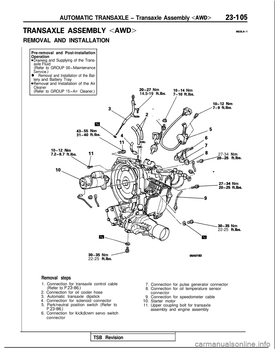
AUTOMATIC TRANSAXLE - Transaxle Assembly 23-I 05
TRANSAXLE ASSEMBLY hl33lA-1
REMOVAL AND INSTALLATION
Pre-removal and Post-installation
Operation
eDraining and Supplying of the Trans-axle Fluid(Refer to GROUP 00-MaintenanceService.)l Removal and Installation of the Bat-tery and Battery Tray
*Removal
and Installation of the Air
Cleaner(Refer to GROUP 15-Air Cleaner.)20-27 Nmlo-14 Nm
14.5-19 ft.lbs.0 /7-10 ft.lbs.
/
, \ fp,/7-9 f%.lbs.
27-34 Nm20-25 ft.lbs.
-27-34 Nm20-25 ft.lbs.
30-35 Nm
22-25 ft.lbs.
30-35 Nm
22-25 ft.lbs. OSA0183
Removal steps
1. Connection for transaxle control cable
(Refer to P.23-86.)2. Connection for oil cooler hose
3. Automatic transaxle dipstick
4. Connection for solenoid connector 5. Park/neutral position switch (Refer to
P.23-86.)6. Connection for kickdown servo switch
connector 7. Connection for pulse generator connector
8. Connection for oil temperature sensor
connector
9. Connection for speedometer cable
10. Starter motor
11. Upper coupling bolt for transaxle
assembly and engine assembly
TSB Revision