1989 MITSUBISHI GALANT oil filter
[x] Cancel search: oil filterPage 437 of 1273
FUEL SYSTEM
of
MFI
Components13-295
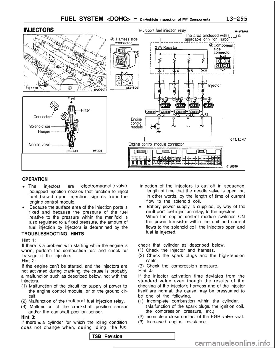
Filter
Connector
Solenoid coil
Plunger
Needle valve -&$
lnjedtion6FUO51
Multiport
fuel injection relayMIBvrbA1
I
The area enclosed with ~~~~ is@I Harness side
applicable onlv for Turbo.
connector
Enginecofitrolmodule
Engine control module connectorI6FU1547
OlLo63
OPERATION
l The injectorsare electromagnetic-valve-
equipped injection nozzles that function to inject
fuel based upon injection signals from the engine control module.
lBecause the surface area of the injection ports is
fixed and because the pressure of the fuel relative to the pressure within the manifold is
also regulated to a fixed pressure, the amount of
fuel injection by injectors is determined by the
TROUBLESHOOTING HINTS
Hint 1:
If there is a problem with starting while the engine is
warm, perform the combustion test and check for leakage of the injectors.Hint 2:
If the engine can’t be started, and the injectors are
not activated during cranking, the cause is probably
a malfunction such as described below, not with the injectors.
(1) Malfunction of the circuit for supply of power to
the engine control module, or of the ground cir-
cuit.
(2) Malfunction of the multiport fuel injection relay.
(3) Malfunction of the crankshaft position sensor and/or the camshaft position sensor.
Hint 3:
If there is a cylinder for which the idling condition
does not change when, during idling, the fuelinjection of the injectors is cut off in sequence,
length of time that the needle valve is open, or,
in other words, by the length of time of current
flow to the solenoid coil.
lBattery power supply is supplied, by way of the
multiport fuel injection relay, to the injectors.
When the engine control module switches ON
the power transistor within the unit and current
flows to the solenoid coil, the injectors open and
fuel is injected.
check that cylinder as described below.
(1) Check the injector and harness.
(2) Check the spark plugs and the high-tension
cable.
(3) Check the compression pressure. Hint 4:
if the injector activation time deviates from the
standard value even though the results of the
checking of the injector’s harness and of the injector
itself are normal, the cause may be pressumed to
be one of the following,
(1) Incomplete combustion within the cylinder.
(Malfunction of the spark plugs, the ignition coil,
the compression pressure, etc.)
(2) Incomplete close contact of the EGR valve seat.
(3) Increased engine resistance.
TSB Revision
Page 467 of 1273
FUEL SYSTEM
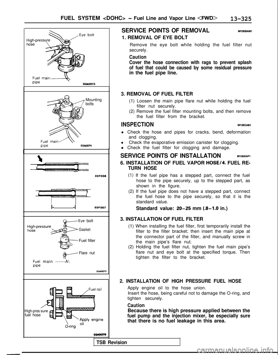
Mounting
bolts 03F008
I--l03FOO7Standard value: 20-25 mm (8-1.0 in.)
t&-----Eye bolt
Gasket
Fuel filter
#-----
Flare nut
;y;; main ------A\
J
I
-.
High-presfuel hose
J-ring
O”
SERVICE POINTS OF REMOVALMlSKBAMl
1. REMOVAL OF EYE BOLT
Remove the eye bolt while holding the fuel filter nut
securely.
Caution
Cover the hose connection with rags to prevent splash
of fuel that could be caused by some residual pressure
in the fuel pipe line.
3. REMOVAL OF FUEL FILTER (1) Loosen the main pipe flare nut while holding the fuelfilter nut securely.
(2) Remove the fuel filter mounting bolts, and then remove the fuel filter from the bracket.
INSPECTIONMlOKCABl
l Check the hose and pipes for cracks, bend, deformationand clogging.
lCheck the evaporative emission canister for clogging.
l Check the fuel filter for clogging and damage.
SERVICE POINTS OF INSTALLATIONMlJKDAPl
6. INSTALLATION OF FUEL VAPOR HOSE/4. FUEL RE-
TURN HOSE
(1) If the fuel pipe has a stepped part, connect the fuel
hose to the pipe securely, up to the stepped part, as
shown in the figure.
(2) If the fuel pipe does not have a stepped part, connect the fuel hose to the pipe securely, so that it is the
standard value.
3. INSTALLATION OF FUEL FILTER (1) When installing the fuel filter, first temporarily install thefilter to the filter bracket; then insert the main pipe at
the connector part of the filter, and manually screw in
the main pipe’s flare nut.
(2) Holding the fuel filter nut, tighten the fuel main pipe’s
flare nut and eye bolt at the specified torque. Then
tighten the filter to the bracket.
TSB Revision 2. INSTALLATION OF HIGH PRESSURE FUEL HOSE
Apply engine oil to the hose union.
Insert the hose, being careful not to damage the O-ring, and
tighten securely.
Caution
Because there is high pressure applied between the
fuel pump and the injection mixer, be especially sure
that there is no fuel leakage in this area.
Page 726 of 1273
23-20AUTOMATIC TRANSAXLE
- Specifications
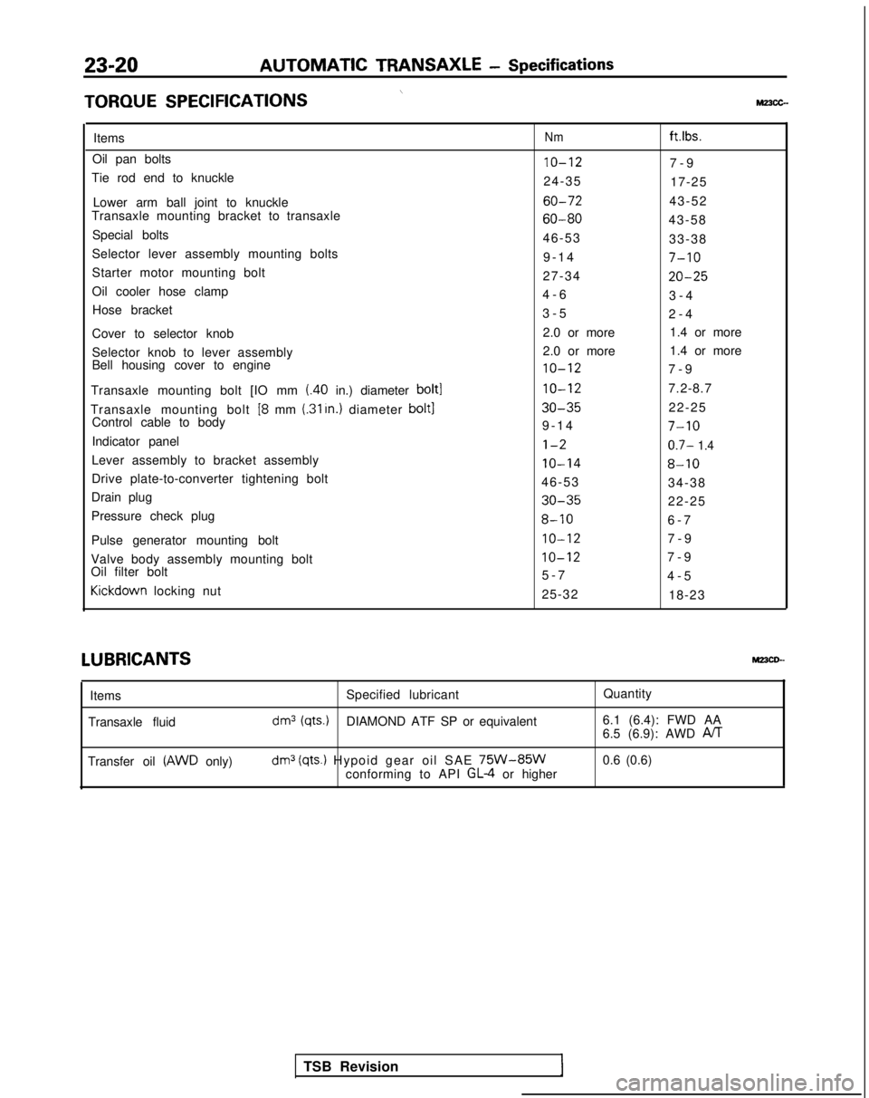
\TORQUE
SPECIFICATIONSMz3cc-
ItemsNmft.lbs.
Oil pan bolts10-127-
9
Tie rod end to knuckle 24-3517-25
Lower arm ball joint to knuckle
60-7243-52
Transaxle mounting bracket to transaxle
60-8043-58
Special bolts 46-5333-38
Selector lever assembly mounting bolts 9-1
4
7-10
Starter motor mounting bolt
27-3420-25
Oil cooler hose clamp4-
6
3-4
Hose bracket 3-52-4
Cover to selector knob 2.0 or more
1.4 or more
Selector knob to lever assembly 2.0 or more
1.4 or more
Bell housing cover to engine
10-127-
9
Transaxle mounting bolt [IO mm
(.40 in.) diameter bolt110-127.2-8.7
Transaxle mounting bolt
[8 mm (.31 In.) diameter bolt130-3522-25
Control cable to body 9-1
4
7-10
Indicator panell-20.7- 1.4
Lever assembly to bracket assembly10-148-10
Drive plate-to-converter tightening bolt
46-5334-38
Drain plug
30-3522-25
Pressure check plug
8-106-
7
Pulse generator mounting bolt
IO-127-
9
Valve body assembly mounting bolt
IO-127-
9
Oil filter bolt 5-74-5Kickdown
locking nut
25-3218-23LUBRICANTS
MPCD--
Items
Transaxle fluid Specified lubricant
Quantity
dm3 (qts.)DIAMOND ATF SP or equivalent6.1 (6.4): FWD AA
6.5 (6.9): AWD PJT
Transfer oil (AWD only)dm3 (qts.) Hypoid gear oil SAE 75W-85Wconforming to API GL-4 or higher0.6 (0.6)
TSB Revision
Page 761 of 1273
AUTOMATIC TRANSAXLE - Troubleshooting23-55
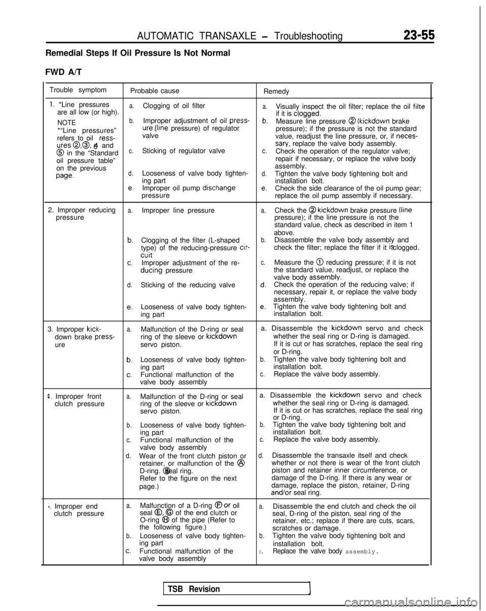
Remedial Steps If Oil Pressure Is Not Normal
FWD A/T Trouble symptom Probable cause Remedy
1. *Line pressuresa.
a.are all low (or high).Clogging of oil filter
Visually inspect the oil filter; replace the oil filte
NOTEb.Improper adjustment of oil press-
if it is cl,ogged.b.Measure line pressure @ (kickdown
brake
*“Line pressures” ure,(line
pressure) of regulator
pressure); if the pressure is not the standard
refers to oil ress-
valve
value, readjust the line pressure, or, if neces-
ures@,@, 4 and
6sary, replace the valve body assembly. @
in the “Standardc.Sticking of regulator valvec.Check the operation of the regulator valve;
oil pressure table” repair if necessary, or replace the valve body
on the previous assembly.
wed.Looseness of valve body tighten-d.Tighten the valve body tightening bolt and
ing part installation bolt.
e.Improper oil pump dischangee.Check the side clearance of the oil pump gear;
pressure replace the oil pump assembly if necessary.
2. Improper reducing
a.Improper line pressurea.Check the @ kickdown
brake pressure /line
pressure pressure); if the line pressure is not the
standard value, check as described in item 1
above.
b.Clogging of the filter (L-shapedb.Disassemble the valve body assembly and
type) of the reducing-pressure cir-
check the filter; replace the filter if it is clogged.
cuitc.Improper adjustment of the re-c.Measure the @ reducing pressure; if it is not
ducing
pressure the standard value, readjust, or replace the
valve body assembly.
d.Sticking of the reducing valved.Check the operation of the reducing valve; if
necessary, repair it, or replace the valve body
assembly.
e.Looseness of valve body tighten-e.Tighten the valve body tightening bolt and
ing part installation bolt.
3. Improper
kick-a.Malfunction of the D-ring or seal a. Disassemble the kickdown
servo and check
down brake press-
ring of the sleeve or kickdown
whether the seal ring or D-ring is damaged.
ure servo piston. If it is cut or has scratches, replace the seal ring
or D-ring.
b.Looseness of valve body tighten-b.Tighten the valve body tightening bolt and
ing part installation bolt.
c.Functional malfunction of thec.Replace the valve body assembly.
valve body assembly
1. Improper front clutch pressurea.Malfunction of the D-ring or seal a. Disassemble the kickdown
servo and check
ring of the sleeve or kickdown
whether the seal ring or D-ring is damaged.
servo piston. If it is cut or has scratches, replace the seal ring
or D-ring.
b.Looseness of valve body tighten-b.Tighten the valve body tightening bolt and
ing part installation bolt.
c.Functional malfunction of thec.Replace the valve body assembly.
valve body assembly
d.Wear of the front clutch piston ord.Disassemble the transaxle itself and check
retainer, or malfunction of the @
whether or not there is wear of the front clutch
D-ring. @ seal ring.
piston and retainer inner circumference, or
Refer to the figure on the next damage of the D-ring. If there is any wear or
page.) damage, replace the piston, retainer, D-ring and/or
seal ring.
i. Improper end
clutch pressurea.Malfunction of a D-ring @or oila.Disassemble the end clutch and check the oil
seal 0.0 of the end clutch or
O-ring 8 of the pipe (Refer to seal, D-ring of the piston, seal ring of the
the following figure.) retainer, etc.; replace if there are cuts, scars,
scratches or damage.
b.Looseness of valve body tighten-b.Tighten the valve body tightening bolt and
ing part installation bolt.
c.Functional malfunction of thec.Replace the valve body assembly.valve body assembly
TSB Revision
Page 763 of 1273
AUTOMATIC TRANSAXLE - Troubleshootinn
23-57
AWD A/T
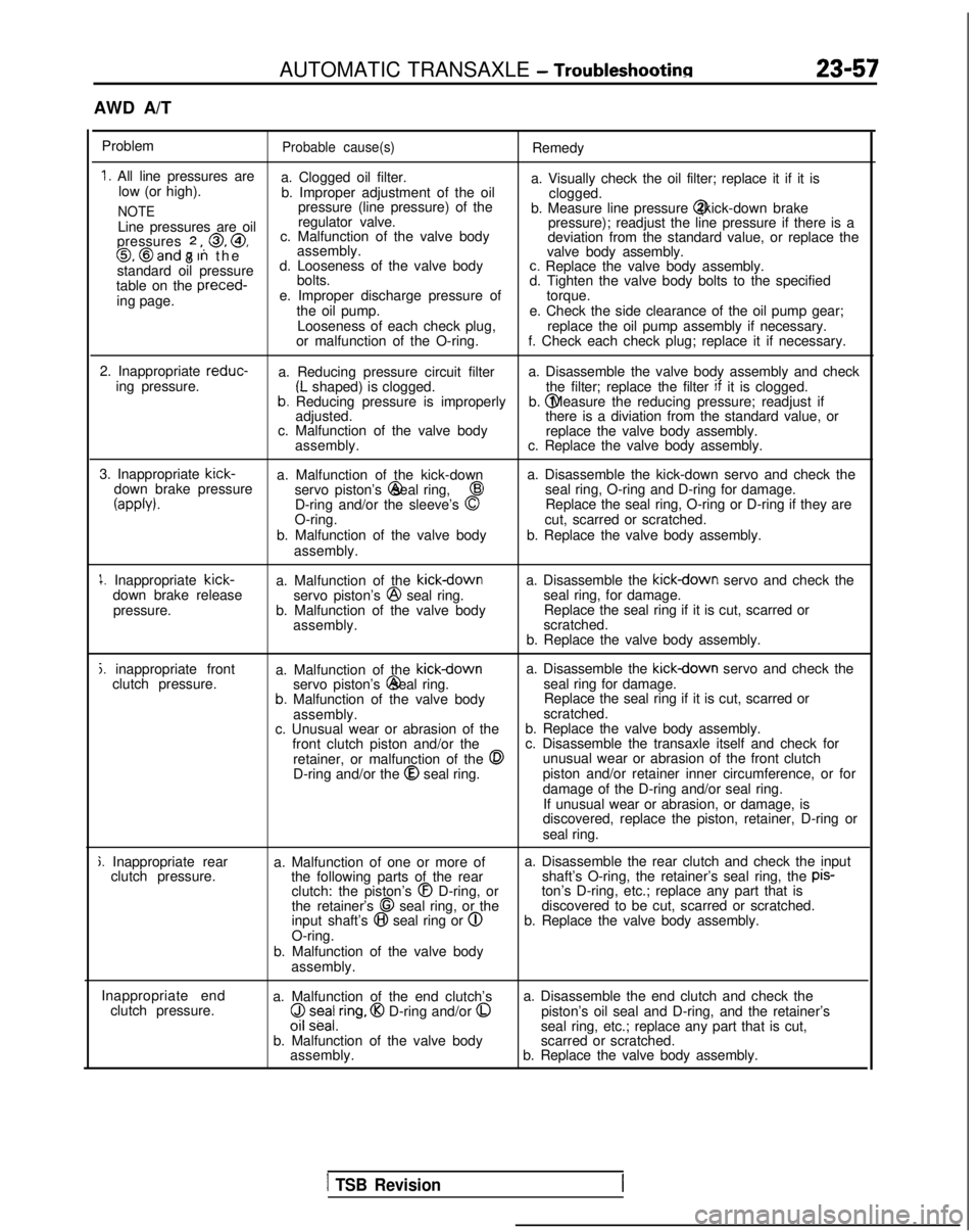
Problem
Probable cause(s)Remedy
1. All line pressures are a. Clogged oil filter.
low (or high). a. Visually check the oil filter; replace it if it is
b. Improper adjustment of the oil clogged.
NOTEpressure (line pressure) of the
b. Measure line pressure @ (kick-down brake
Line pressures are oil regulator valve.
pressure); readjust the line pressure if there is a
pressures
2 ,, 0, @,
8 c. Malfunction of the valve body
deviation from the standard value, or replace the0, @and 7 In th
e
assembly.
valve body assembly.
standard oil pressure d. Looseness of the valve body
c. Replace the valve body assembly.
table on the preced-
bolts.
d. Tighten the valve body bolts to the specified
ing page. e. Improper discharge pressure of
torque.
the oil pump. e. Check the side clearance of the oil pump gear;
Looseness of each check plug, replace the oil pump assembly if necessary.
or malfunction of the O-ring. f. Check each check plug; replace it if necessary.
2. Inappropriate reduc-
a. Reducing pressure circuit filter a. Disassemble the valve body assembly and check
ing pressure.
(L shaped) is clogged. the filter; replace the filter if
it is clogged.b. Reducing pressure is improperly b. @ Measure the reducing pressure; readjust if
adjusted. there is a diviation from the standard value, or
c. Malfunction of the valve body replace the valve body assembly.
assembly. c. Replace the valve body assembly.
3. Inappropriate kick-
a. Malfunction of the kick-down a. Disassemble the kick-down servo and check the
down brake pressure servo piston’s @ seal ring,
43seal ring, O-ring and D-ring for damage.
(appb).D-ring and/or the sleeve’s 0Replace the seal ring, O-ring or D-ring if they are
O-ring. cut, scarred or scratched.
b. Malfunction of the valve body b. Replace the valve body assembly.
assembly.
1. Inappropriate kick-
down brake release
pressure. a. Malfunction of the kickdownservo piston’s @
seal ring.
b. Malfunction of the valve body assembly. a. Disassemble the kickdown servo and check the
seal ring, for damage. Replace the seal ring if it is cut, scarred or
scratched.
b. Replace the valve body assembly.
j. inappropriate front clutch pressure. a. Malfunction of the kickdowna. Disassemble the kickdown servo and check the
servo piston’s @ seal ring.
seal ring for damage.
b. Malfunction of the valve body Replace the seal ring if it is cut, scarred or
assembly. scratched.
c. Unusual wear or abrasion of the b. Replace the valve body assembly.
front clutch piston and/or the c. Disassemble the transaxle itself and check for
retainer, or malfunction of the
0unusual wear or abrasion of the front clutch
D-ring and/or the @
seal ring. piston and/or retainer inner circumference, or for
damage of the D-ring and/or seal ring.
If unusual wear or abrasion, or damage, is
discovered, replace the piston, retainer, D-ring or
seal ring.
j. Inappropriate rear clutch pressure. a. Malfunction of one or more of
the following parts of the rearclutch: the piston’s
@I D-ring, or
the retainer’s 68 seal ring, or the
input shaft’s @I seal ring or @
O-ring.
b. Malfunction of the valve body assembly. a. Disassemble the rear clutch and check the input
shaft’s O-ring, the retainer’s seal ring, the pis-
ton’s D-ring, etc.; replace any part that is
discovered to be cut, scarred or scratched.
b. Replace the valve body assembly.
Inappropriate end clutch pressure. a. Malfunction of the end clutch’s
($ z;ea/,ring, @I D-ring and/or 0
b. Malfunction of the valve body
assembly. a. Disassemble the end clutch and check the
piston’s oil seal and D-ring, and the retainer’s
seal ring, etc.; replace any part that is cut,
scarred or scratched.
b. Replace the valve body assembly.
1 TSB Revision
Page 794 of 1273
23-88AUTOMATIC TRANSAXLE - Service Adjustment Procedures
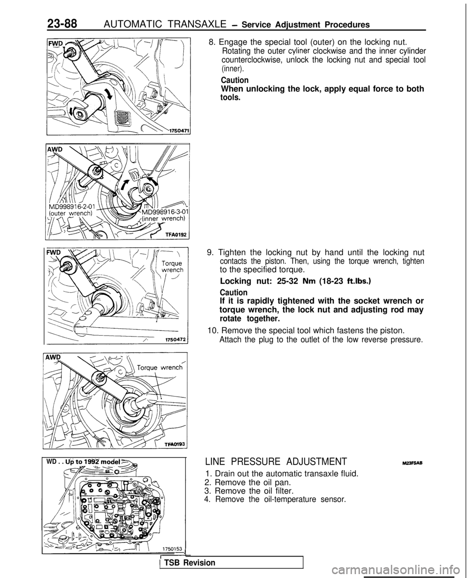
8. Engage the special tool (outer) on the locking nut.
Rotating the outer cyliner clockwise and the inner cylinder
counterclockwise, unlock the locking nut and special tool
(inner).
Caution
When unlocking the lock, apply equal force to both
tools.
WD . . . Up to 1992 model -
&@~o-&q
9. Tighten the locking nut by hand until the locking nut
contacts the piston. Then, using the torque wrench, tighten
to the specified torque.
Locking nut: 25-32
Nm (18-23 ft.lbs.)
Caution
If it is rapidly tightened with the socket wrench or
torque wrench, the lock nut and adjusting rod may
rotate together.
10. Remove the special tool which fastens the piston.
Attach the plug to the outlet of the low reverse pressure.
LINE PRESSURE ADJUSTMENT
1. Drain out the automatic transaxle fluid.
2. Remove the oil pan.
3. Remove the oil filter.
4. Remove the oil-temperature sensor.
J
1 TSB Revision
M23F9A9
Page 797 of 1273
AUTOMATIC TRANSAXLE -Service Adjustment Procedures23-91
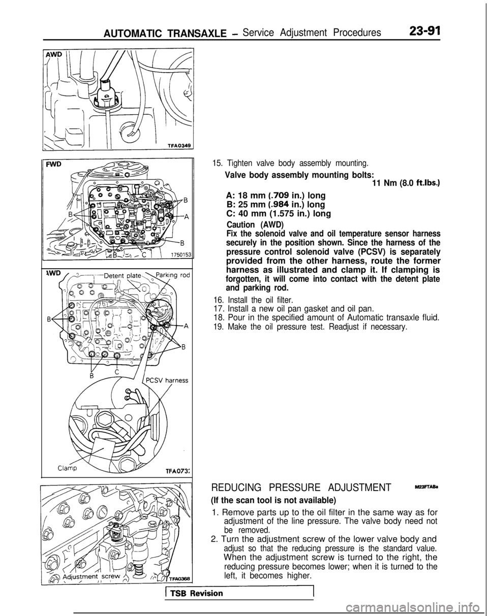
15. Tighten valve body assembly mounting.
Valve body assembly mounting bolts:11 Nm (8.0 ftlbs.)
A: 18 mm (.709
in.) long
B: 25 mm (.984
in.) long
C: 40 mm (1.575 in.) long
Caution (AWD)
Fix the solenoid valve and oil temperature sensor harness
securely in the position shown. Since the harness of the
pressure control solenoid valve (PCSV) is separately
provided from the other harness, route the former
harness as illustrated and clamp it. If clamping is
forgotten, it will come into contact with the detent plate and parking rod.
16. Install the oil filter.
17. Install a new oil pan gasket and oil pan.
18. Pour in the specified amount of Automatic transaxle fluid.
19. Make the oil pressure test. Readjust if necessary.
REDUCING PRESSURE ADJUSTMENTMZ3FTAb
(If the scan tool is not available)
1. Remove parts up to the oil filter in the same way as for
adjustment of the line pressure. The valve body need not
be removed.
2. Turn the adjustment screw of the lower valve body and
adjust so that the reducing pressure is the standard value.
When the adjustment screw is turned to the right, the
reducing pressure becomes lower; when it is turned to the
left, it becomes higher.
Page 798 of 1273
23-92AUTOMATIC TRANSAXLE - Service Adjustment Procedures
NOTE
When adjusting the reducing pressure, aim for the center
value (425 kPa, 60 psi) of the standard value allowance.
Standard value: 415-435
kPa (59-62 psi)
Oil pressure change for each turn of adjustment screw: 22
kPa (3.1 psi) . . . FWD (Up to MODEL 1990)
45
kPa (6.4 psi) . . . FWD (From MODEL 1990.5, AWD)
3. Install the oil filter and oil pan in the same way as for adjustment of the line pressure.
4. Make the oil pressure test. Readjust if necessary.
(If the scan tool is used)
1. Using the scan tool, forcibly drive the pressure control
solenoid valve at 50% duty, and measure the kick-down
brake apply pressure.
If the kick-down brake apply pressure does not exist within
the standard value width, adjust the pressure with the
reducing pressure adjustment screw.
Standard value: 275 + 10 kPa (39 + 1 psi)
Oil pressure change for each turn of adjustment screw:
25 kPa (3.6 psi) FWD (Up to MODEL 1990)
22
kPa (3.1 psi) FWD (From MODEL 1990.5), AWD
2. Check to be sure that the reducing pressure (after the
adjustment is completed) is within the range of 360-480
kPa (51 -68 psi.).
Caution
This adjustment should be made at an oil
temperature
of 70- 80°C
(160- 180°F).
If the adjustment is made at a temperature that is too
high, the line pressure will drop during idling, with the
result that it might not be possible to make the correct
adjustment.
I / Oii
seal09K561
THROTTLE-POSITION SENSOR ADJUSTMEF&
Refer to GROUP 13-On-Vehicle Inspection of MFI Compo-
nents.
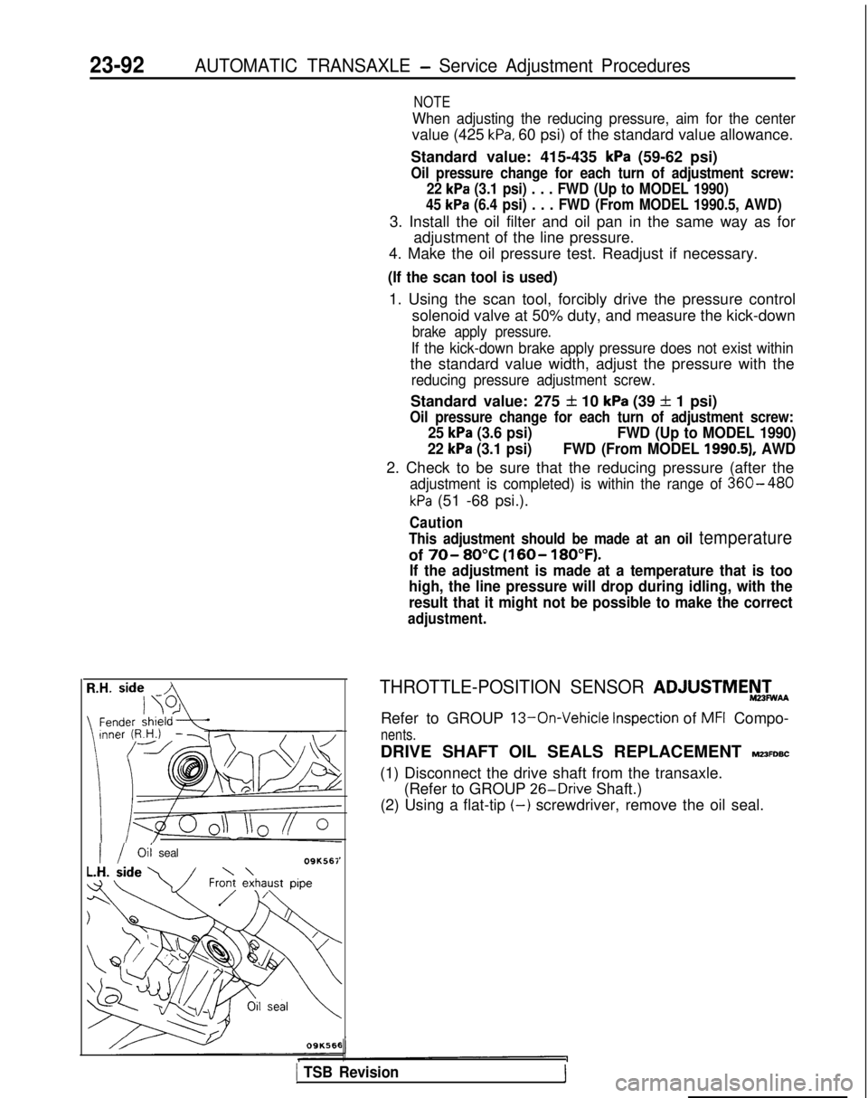
DRIVE SHAFT OIL SEALS REPLACEMENT MZ3FDBC
(1) Disconnect the drive shaft from the transaxle. (Refer to GROUP 26-Drive
Shaft.)
(2) Using a flat-tip
(-) screwdriver, remove the oil seal.
1 TSB Revision1