1989 MITSUBISHI GALANT spark plugs
[x] Cancel search: spark plugsPage 207 of 1273
FUEL SYSTEM
(1) Improper adjustment of the basic idling speed.
(2) Deposits adhering to the ttirottle valve.
(3) Air being taken into the intake manifold due to a gasket leak, etc.
OPERATION
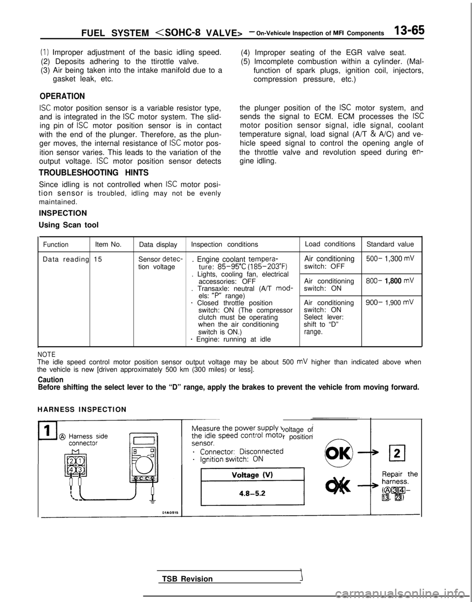
ISC motor position sensor is a variable resistor type,
and is integrated in the
ISC motor system. The slid-
ing pin of
ISC motor position sensor is in contact
with the end of the plunger. Therefore, as the plun- ger moves, the internal resistance of
ISC motor pos-
ition sensor varies. This leads to the variation of the (4) Improper seating of the EGR valve seat.
(5) lmcomplete combustion within a cylinder. (Mal-
function of spark plugs, ignition coil, injectors,
compression pressure, etc.)
the plunger position of the
ISC motor system, and
sends the signal to ECM. ECM processes the
ISC
motor position sensor signal, idle signal, coolant
temperature signal, load signal (A/T &
A/C) and ve-
hicle speed signal to control the opening angle of
the throttle valve and revolution speed during
en-
output voltage. ISC motor position sensor detects gine idling.
TROUBLESHOOTING HINTS
Since idling is not controlled when ISC motor posi-
tion sensor is troubled, idling may not be evenly
maintained.
INSPECTION
Using Scan tool
FunctionItem No. Data display Inspection conditions Load conditions
Standard value
Data reading 15 Sensor detec-
. Engine coolant tempera-
Air conditioning 500- 1,300 mV
tion voltage
ture: 85-95’C (185-203°F)
switch: OFF
. Lights, cooling fan, electrical accessories: OFF Air conditioning 800-
1,800 mV. Transaxle: neutral (A/T
mod-
switch: ON
els: “P”
range)
1 Closed throttle position Air conditioning900- 1,900 mVswitch: ON (The compressorswitch: ON
clutch must be operating Select lever:
when the air conditioning shift to “D”
switch is ON.)
range.* Engine: running at idle
NOTEThe idle speed control motor position sensor output voltage may be about\
500 mV higher than indicated above when
the vehicle is new [driven approximately 500 km (300 miles) or less].
CautionBefore shifting the select lever to the “D” range, apply the brake\
s to prevent the vehicle from moving forward.
HARNESS INSPECTION
Measure the power supply voltage of
the idle speed control motor position
ei;;;it;;sco$ected
__...._ -.-
TSB Revision
Page 232 of 1273
13-90 FUEL SYSTEM
INJECTORS
Fuel
Connector
Solenoid coil
Plunger
Needle valve -----I
InjectionFilter6FUO514
M13rrAA
Multiport
fuel injection relay
No.1 &j No.2& No.3& No,4+
tI
lFUO642
Engine control module connector
CJ=JW=U-I
0 1 LO636
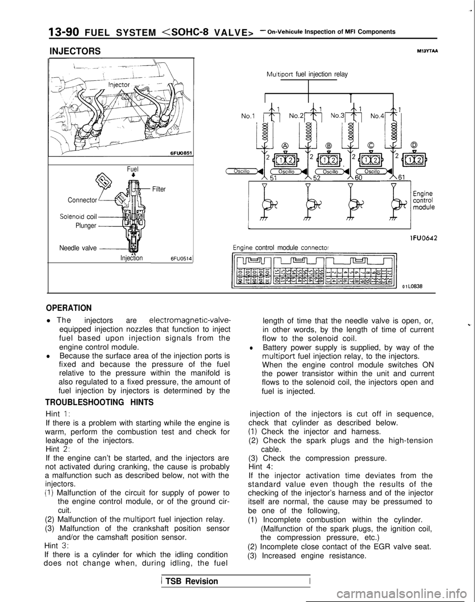
OPERATION
l The
injectorsare electromagnetic-valve-
equipped injection nozzles that function to inject
fuel based upon injection signals from the
engine control module.
lBecause the surface area of the injection ports is
fixed and because the pressure of the fuel
relative to the pressure within the manifold is
also regulated to a fixed pressure, the amount of
fuel injection by injectors is determined by the
TROUBLESHOOTING HINTS
Hint 1:
If there is a problem with starting while the engine is
warm, perform the combustion test and check for leakage of the injectors.
Hint
2,
If the engine can’t be started, and the injectors are
not activated during cranking, the cause is probably
a malfunction such as described below, not with the
injectors.
(I) Malfunction of the circuit for supply of power to the engine control module, or of the ground cir-
cuit.
(2) Malfunction of the multiport fuel injection relay.
(3) Malfunction of the crankshaft position sensor and/or the camshaft position sensor.
Hint
3.
If there is a cylinder for which the idling condition
does not change when, during idling, the fuel length of time that the needle valve is open, or,
in other words, by the length of time of current
~-
flow to the solenoid coil.
lBattery power supply is supplied, by way of the
multiport fuel injection relay, to the injectors.
When the engine control module switches ON
the power transistor within the unit and current
flows to the solenoid coil, the injectors open and
fuel is injected.
injection of the injectors is cut off in sequence,
check that cylinder as described below.
(1) Check the injector and harness.
(2) Check the spark plugs and the high-tension
cable.
(3) Check the compression pressure. Hint 4:
If the injector activation time deviates from the
standard value even though the results of the
checking of the injector’s harness and of the injector itself are normal, the cause may be pressumed to
be one of the following,
(1) Incomplete combustion within the cylinder. (Malfunction of the spark plugs, the ignition coil,
the compression pressure, etc.)
(2) Incomplete close contact of the EGR valve seat.
(3) Increased engine resistance.
1 TSB RevisionI
Page 276 of 1273
13-134FUEL SYSTEM (SOHC-16 VALVE> -Service Adjustment Procedures
BASIC IDLE SPEED ADJUSTMENTMlIFHBX
NOTE
1. The standard idling speed has been adjusted, by the en-
gine speed adjusting screw, by the manufacturer, and
there should usually be no need for readjustment.
2. Use the following procedure to adjust when the idling speed drops due to an incorrect adjustment, high idling
speed, or when a load such as the air conditioning is ap-
plied on the engine.
3. The adjustment, if made, should be made after first con- firming that the spark plugs, the injectors, the idle air con-
trol motor, the compression pressure, etc. are all normal.
(I ) The vehicle should be prepared as follows before the inspec- tion and adjustment.
l Engine coolant temperature:
85-95°C (185-203°F)
l Lights, cooling fan and accessories: OFF
l Transaxle: neutral (A/T for
P range)
l Steering wheel: neutral position
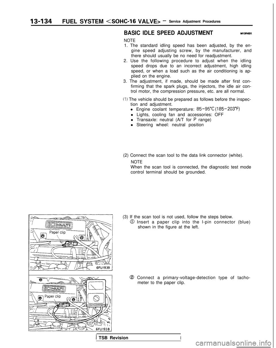
(2) Connect the scan tool to the data link connector (white).
NOTE
When the scan tool is connected, the diagnostic test mode control terminal should be grounded.
(3) If the scan tool is not used, follow the steps below.
@I Insert a paper clip into the l-pin connector (blue) shown in the figure at the left.
0 Connect a primary-voltage-detection type of tacho-meter to the paper clip.
1 TSB RevisionI
Page 387 of 1273
FUEL SYSTEM
cl989 models> -a’i\.-upI t
SERVICE ADJUSTMENT PROCEDURES
CURB IDLE SPEED INSPECTION
MlSFHAB
(1) The vehicle should be prepared as follows before the inspection.
l Engine coolant temperature:
85-95°C (185-205°F)
l Lights, electric cooling fan and accessories: OFF
l Transaxle: Neutral
(P for vehicles with an automatic
transaxle)
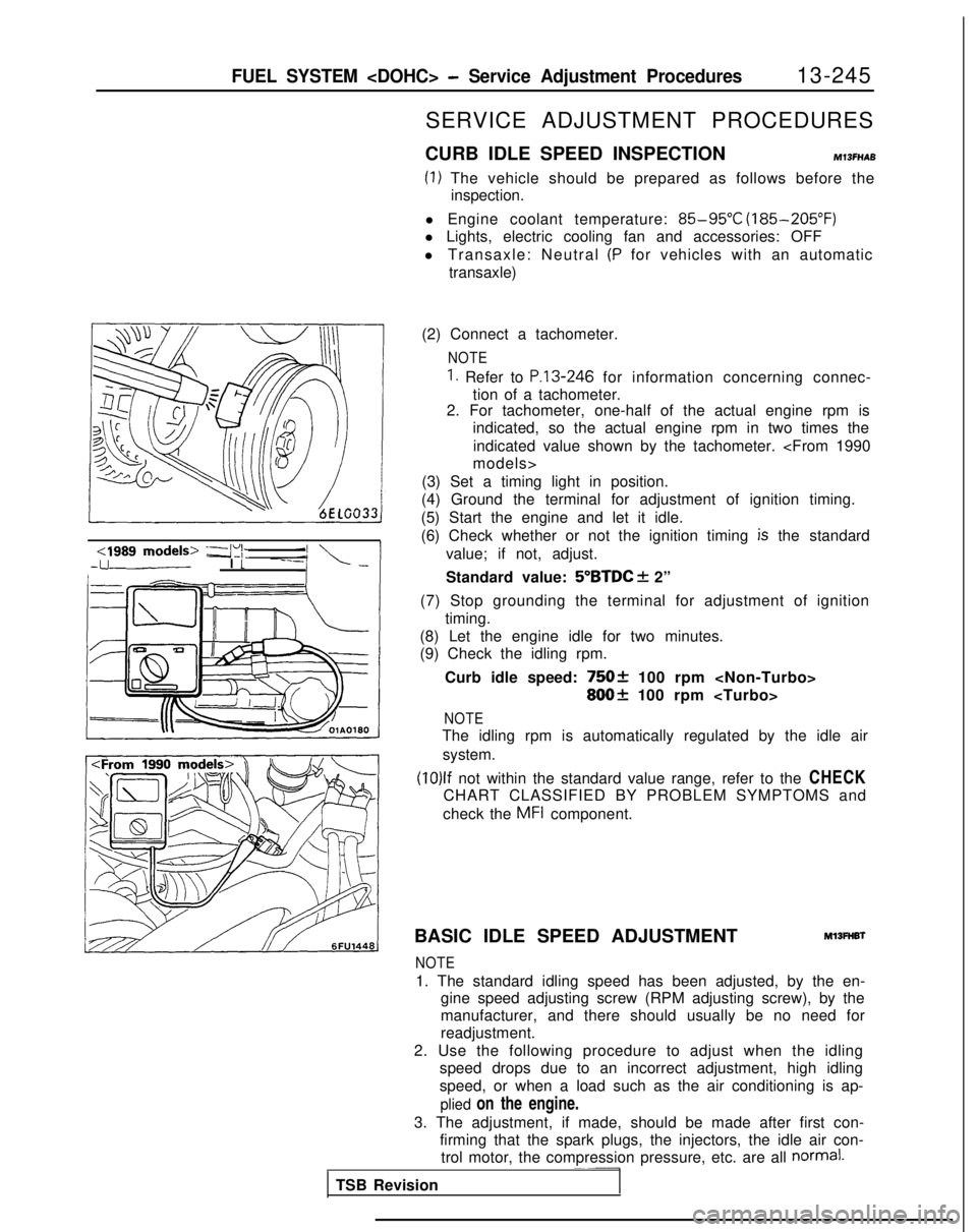
(2) Connect a tachometer.
NOTE
1. Refer to P.13-246 for information concerning connec-
tion of a tachometer.
2. For tachometer, one-half of the actual engine rpm is
indicated, so the actual engine rpm in two times the
indicated value shown by the tachometer.
(3) Set a timing light in position.
(4) Ground the terminal for adjustment of ignition timing.
(5) Start the engine and let it idle.
(6) Check whether or not the ignition timing
is the standard
value; if not, adjust.
Standard value:
5”BTDC f 2”
(7) Stop grounding the terminal for adjustment of ignition timing.
(8) Let the engine idle for two minutes.
(9) Check the idling rpm.
Curb idle speed:
75Ok 100 rpm
800+ 100 rpm
NOTE
The idling rpm is automatically regulated by the idle airsystem.
(10)lf not within the standard value range, refer to the CHECK
CHART CLASSIFIED BY PROBLEM SYMPTOMS and
check the
MFI component.
BASIC IDLE SPEED ADJUSTMENT
Ml3FHBl
NOTE
1. The standard idling speed has been adjusted, by the en- gine speed adjusting screw (RPM adjusting screw), by the
manufacturer, and there should usually be no need for
readjustment.
2. Use the following procedure to adjust when the idling speed drops due to an incorrect adjustment, high idling
speed, or when a load such as the air conditioning is ap-
plied on the engine.
3. The adjustment, if made, should be made after first con- firming that the spark plugs, the injectors, the idle air con-trol motor, the compression pressure, etc. are all
normal.~~-
TSB Revision
Page 403 of 1273
FUEL SYSTEM
VOLUME AIR FLOW SENSORMlWFAAs
/
side
@Harness side connector
I@ Harness sideconnector
Fnnine control module connector
Multiport fuel
The area enclosed with :I: is injection relay
applicable only for Turbo vehicle.
I
@I Component connector (Filter reset circuit)
Engine control module
6FU1537
Intake air amount (Wsec)
162451
OlLO838
OPERATION
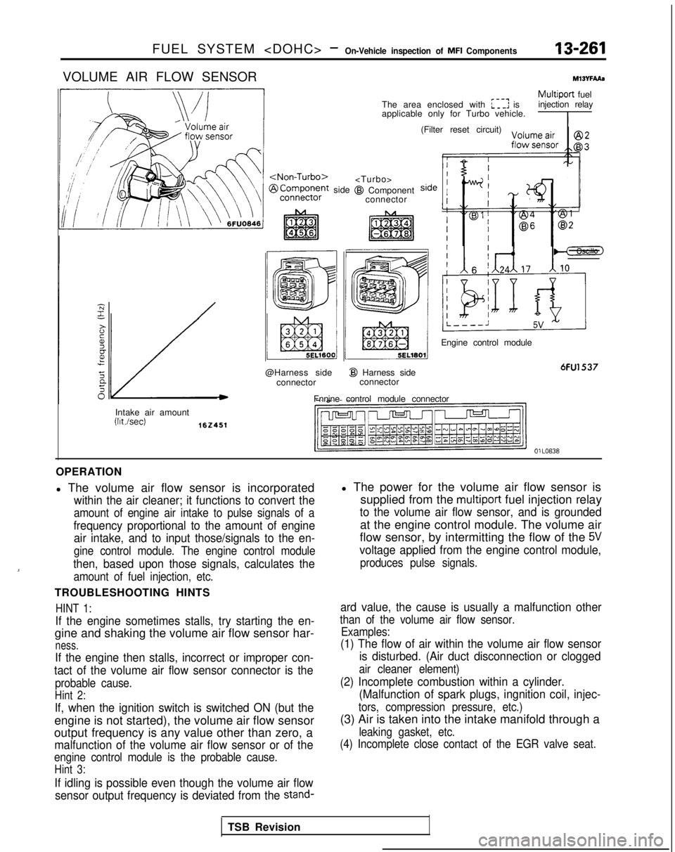
l The volume air flow sensor is incorporated
within the air cleaner; it functions to convert the
amount of engine air intake to pulse signals of a
frequency proportional to the amount of engine air intake, and to input those/signals to the en-
gine control module. The engine control module
then, based upon those signals, calculates the
amount of fuel injection, etc.
TROUBLESHOOTING HINTS
HINT 1:
If the engine sometimes stalls, try starting the en-
gine and shaking the volume air flow sensor har-
ness.
If the engine then stalls, incorrect or improper con-
tact of the volume air flow sensor connector is the
probable cause.
Hint 2:
If, when the ignition switch is switched ON (but the
engine is not started), the volume air flow sensor
output frequency is any value other than zero, a
malfunction of the volume air flow sensor or of the
engine control module is the probable cause.
Hint 3:
If idling is possible even though the volume air flow
sensor output frequency is deviated from the
stand-
l The power for the volume air flow sensor is supplied from the
multiport fuel injection relay
to the volume air flow sensor, and is grounded
at the engine control module. The volume air
flow sensor, by intermitting the flow of the
5V
voltage applied from the engine control module,
produces pulse signals.
ard value, the cause is usually a malfunction other
than of the volume air flow sensor. Examples:
(1) The flow of air within the volume air flow sensor
is disturbed. (Air duct disconnection or clogged
air cleaner element)
(2) Incomplete combustion within a cylinder.(Malfunction of spark plugs, ingnition coil, injec-
tors, compression pressure, etc.)
(3) Air is taken into the intake manifold through a
leaking gasket, etc.
(4) Incomplete close contact of the EGR valve seat.
TSB Revision
Page 437 of 1273
FUEL SYSTEM
of
MFI
Components13-295
Filter
Connector
Solenoid coil
Plunger
Needle valve -&$
lnjedtion6FUO51
Multiport
fuel injection relayMIBvrbA1
I
The area enclosed with ~~~~ is@I Harness side
applicable onlv for Turbo.
connector
Enginecofitrolmodule
Engine control module connectorI6FU1547
OlLo63
OPERATION
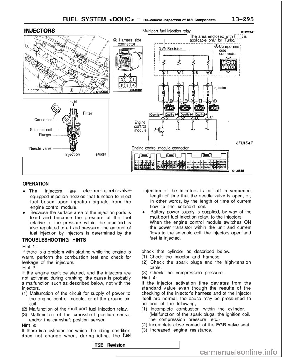
l The injectorsare electromagnetic-valve-
equipped injection nozzles that function to inject
fuel based upon injection signals from the engine control module.
lBecause the surface area of the injection ports is
fixed and because the pressure of the fuel relative to the pressure within the manifold is
also regulated to a fixed pressure, the amount of
fuel injection by injectors is determined by the
TROUBLESHOOTING HINTS
Hint 1:
If there is a problem with starting while the engine is
warm, perform the combustion test and check for leakage of the injectors.Hint 2:
If the engine can’t be started, and the injectors are
not activated during cranking, the cause is probably
a malfunction such as described below, not with the injectors.
(1) Malfunction of the circuit for supply of power to
the engine control module, or of the ground cir-
cuit.
(2) Malfunction of the multiport fuel injection relay.
(3) Malfunction of the crankshaft position sensor and/or the camshaft position sensor.
Hint 3:
If there is a cylinder for which the idling condition
does not change when, during idling, the fuelinjection of the injectors is cut off in sequence,
length of time that the needle valve is open, or,
in other words, by the length of time of current
flow to the solenoid coil.
lBattery power supply is supplied, by way of the
multiport fuel injection relay, to the injectors.
When the engine control module switches ON
the power transistor within the unit and current
flows to the solenoid coil, the injectors open and
fuel is injected.
check that cylinder as described below.
(1) Check the injector and harness.
(2) Check the spark plugs and the high-tension
cable.
(3) Check the compression pressure. Hint 4:
if the injector activation time deviates from the
standard value even though the results of the
checking of the injector’s harness and of the injector
itself are normal, the cause may be pressumed to
be one of the following,
(1) Incomplete combustion within the cylinder.
(Malfunction of the spark plugs, the ignition coil,
the compression pressure, etc.)
(2) Incomplete close contact of the EGR valve seat.
(3) Increased engine resistance.
TSB Revision
Page 441 of 1273
FUEL SYSTEM
MFI Components13-299
OPERATION
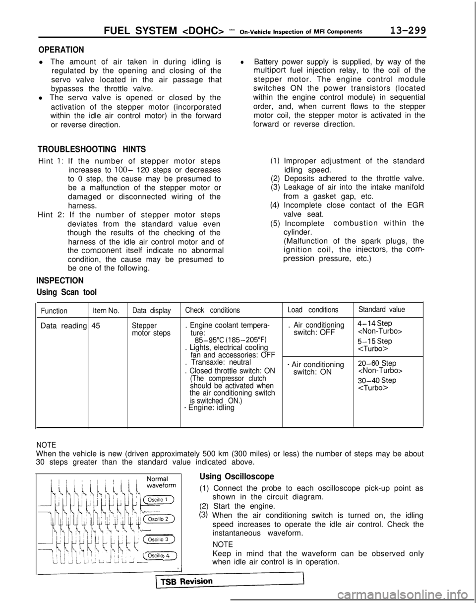
l The amount of air taken in during idling is
regulated by the opening and closing of the
servo valve located in the air passage that
bypasses the throttle valve.
l The servo valve is opened or closed by the
activation of the stepper motor (incorporated
within the idle air control motor) in the forward
or reverse direction.
TROUBLESHOOTING HINTS
Hint 1: If the number of stepper motor steps increases to
IOO- 120 steps or decreases
to 0 step, the cause may be presumed to be a malfunction of the stepper motor or
damaged or disconnected wiring of the
harness.
Hint 2: If the number of stepper motor steps
deviates from the standard value even
though the results of the checking of the
harness of the idle air control motor and of
the comoonent
itself indicate no abnormal
condition, the cause may be presumed to be one of the following.
INSPECTION
Using Scan tool
lBattery power supply is supplied, by way of the
multiport fuel injection relay, to the coil of the
stepper motor. The engine control module
switches ON the power transistors (located
within the engine control module) in sequential
order, and, when current flows to the stepper motor coil, the stepper motor is activated in the
forward or reverse direction.
(1) Improper adjustment of the standard
idling speed.
(2) Deposits adhered to the throttle valve.
(3) Leakage of air into the intake manifold
from a gasket gap, etc.
(4) Incomplete close contact of the EGRvalve seat.
(5) Incomplete combustion within the
cylinder.
(Malfunction of the spark plugs, the
ignition coil, the iniectors,
the
com- pression
pressure, etc.)
FunctionItem No.Data display Check conditions Load conditionsStandard value
Data reading 45Steppermotor steps. Engine coolant tempera-
. Air conditioning
4-14Step
ture:switch: OFF
(185-205°F)
. Lights, electrical cooling
:$b::pfan and accessories: OFF
. Transaxle: neutral
. Closed throttle switch: ON
- Air conditioning 20-60 Step
switch: ON
(The compressor clutchshould be activated when
the air conditioning switch;J-;;o~P
is switched ON.)* Engine: idling
1;:!,1;:!,
/!-I\/!-I\
f$&$:”f$&$:”
! ,‘,! ,‘,
4);4);
;jj\(Q(j!jGZ-);jj\(Q(j!jGZ-)
lili
q#Q~Hq#Q~HF]F]
ii 2 L J 2 L ~ -0SClllO 4ii 2 L J 2 L ~ -0SClllO 4
NOTE
When the vehicle is new (driven approximately 500 km (300 miles) or l\
ess) the number of steps may be about
30 steps greater than the standard value indicated above.
Using Oscilloscope
(1) Connect the probe to each oscilloscope pick-up point as
shown in the circuit diagram.
(2) Start the engine.
(3) When the air conditioning switch is turned on, the idling speed increases to operate the idle air control. Check theinstantaneous waveform.
NOTE
Keep in mind that the waveform can be observed only
when idle air control is in operation.
Page 1268 of 1273
ALPHABETICAL INDEX
PLUGSpark, Maintenance. 00-40-I
Spark, Test..
16-42-11
POSITIVE CRANKCASE VENTILATION SYSTEM 17-13-l
POSITIVE CRANKCASE VENTILATION (PCV) VALVE,Inspection
17-14-I
POWER AMPLIFIER
54-151-11POWER CYLINDE
R
378-9-I
POWER GROUND
Engine Control Module, On-vehicle
Inspection
Engrne Control Module, On-vehicle Inspection
.
13-45-l
Engine Control Module, On-vehicle Inspection
.
13-146-I
POWER RELAY
ABS. Check
................................
.
35-74-l
Air
Conditionrng and Ventrlation. Check ........
.
55-24-l
POWER STEERING, Stationary Steering Effort Check......
.
37A-18-l
POWER STEERING FLUID
Level Check
.................................
.
37A-21-l
Replacement .................................... 37A-21-I
POWER STEERING GEAR 80X....................
.
37A-32-l
POWER STEERING HOSES...........
.
........ 37A-58-l
POWER STEERING OIL PUMP......................
.
37A-48-l
POWER STEERING OIL PUMP, Pressure Test...........
.
37A-23-l
POWER STEERING PRESSURE SWITCH
Check
........................................
.
37A-24-l
On-vehicle Inspection
On-vehicle Inspection
.
13-81 -IOn-vehicle Inspection
.
13-175-l
POWER SUPPLY
On-vehicle Inspectron
.................
.
13-255-l
On-vehicle Inspection
.
13-42-I
On-vehrcle Inspection
.
13-143-l
POWER TRANSISTOR
Ignition, On-vehicle Inspection
............
.
13-302-I
Ignition, On-vehicle Inspection
.
13-96-l
Ignition, On-vehicle Inspection
POWER WINDOW..................................
.
42-86-l
PRESSURECompression, Check
....................
.
11-59-i
Compression, Check
1 l-8-lFuel, On-vehicle Inspection
.
13-312-I
Fuel, On-vehicle Inspection
.
13-102-I
Fuel, On-vehicle Inspection
.
13-192-l
Inflation,Tire,
Check
............................ 31-4-I
Line, Adjustment .................................. 23-88-l
Reducing, Adjustment ........................
23-91 -IPRESSURE SWITCH
Brake Fluid
....
.
35-133-I
Brake Fluid, Check AWD-ABS: Up to 1991 Models> ..... 35-75-l
PROPELLER SHAFT.................................
.
25-4-l
PROPORTIONING VALVE, Function Test................
.
35-56-l
PUMP
Fuel, On-vehicle Inspection
Fuel, On-vehicle Inspection
.
13-46-l
Fuel, On-vehicle Inspection
.
13-147-l
OiLRear
....................................... 37B-15-l
Water
................................ 14-20-I
Water
14-I 5-1PURGE CONTROL SYSTEM
Inspection
.........................
.
17-17-I
Inspection
PURGE CONTROL VALVE
PURGE PORT VACUUM............................
.
17-19-I
Q
QUARTER WINDOW GLASS......................
.
42-70-I
R
RADIATOR.........................................
.
14-9-lRADIATOR CAP, Pressure Test
.......................
.
14-8-lRADIATOR FAN MOTOR
............................
.
14-12-lRADIO AND TAPE PLAYER
..........................
.
54-149-11REAR AXLE
Maintenance
.............................
.
00-45-I
Total Backlash Check
.
27-15-I
REAR AXLE HUB
FWD-Rear Disc Brakes
.............................
.
27-8-l
FWD-Rear Drum Brakes ........................... 27-6-l
REAR BRAKE DISC
Run-out Check.
.................................
.
35-66-l
Run-out Correction .............................. 35-66-l
Thickness Check ............................... 35-66-l
REAR BRAKE WHEEL CYLINDER......................
.
35-l 1 l-lREAR COMBINATION LIGHT
..........................
.
54-95-IREAR DISC BRAKE.................................
.
35-l 14-lREAR DISC BRAKE PAD, Check and Replacement
.........
. 35-65-l
REAR DOOR DRIP LINE WEATHERSTRIP.............
.
42-l 14-lREAR DOOR GLASS.........................
.
42-83-l
REAR DOOR HANDLE............................
.
42-99-l
REAR DOOR LATCH................................
.
42-99-l
REAR DOOR
MOULDING
........................42-l 14-l
REAR DOOR REGULATOR..........................
.
42-83-l
REAR DOOR TRIM................................
.
42-78-l
REAR DOOR WATERPROOF FILM......................
.
42-78-l
REAR DRUM BRAKE...............................
.
35-108-I
REAR DRUM BRAKE LININGS, Maintenance ............... 00-44-I
REAR HUB, Rotary-sliding Resistance (Torque)
Adjustment
.
27-5-l
REAR OIL LINE..................................
.
378-13-I
REAR OIL PUMP
Discharge Flow Volume Check .................... 378-6-I
4WS
........................................... 378-15-I
REAR SEAT......................................
.
52-37-l
REAR SUSPENSION
Active-ECS
...................................
.
338-l 14-lAWD
..........................................
.
34-24-l
FWD..........................................
.
34-6-l
REAR WHEEL ALIGNMENT Inspection
.
34-23-l
Inspection
.
34-5-l
REAR WHEEL BEARING
End Play Check
.
27-15-I
‘Rotation Sliding Resistance Check
.
27-16-I
REAR WHEEL CYLINDERS, Maintenance, 00-44-I
REAR WINDOW
DEFFOGER..........................
.
54-156-11REAR WINDOW DEFOGGER SWITCH..................
.
54-163-11REAR WINDOW GLASS..............................
.
42-72-l
REDUCING PRESSURE, Adjustment. ..................... 23-91-l
REFRIGERANT, Leak Repair Procedure.................
.
55-21-l
REFRIGERANT LINE..................................
55-54-l
REGULATOR
Door, Front
.....................................
.
42-80-I
Door, Rear ....................................... 42-83-l
RELAY
A/C Compressor Clutch, On-vehicle Inspection
.
13-83-lA/C Compressor Clutch, On-vehicle Inspection
13-176-I