Page 1037 of 1273

33B-98ACTIVE-ELECTRONIC CONTROL SUSPENSION - Strut Assembly i
SERVICE POINTS OF REMOVALM33lBAE
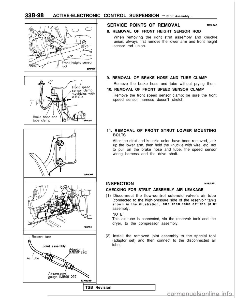
8. REMOVAL OF FRONT HEIGHT SENSOR RODWhen removing the right strut assembly and knuckleunion, always first remove the lower arm and front height
sensor rod union. l1RoooP
-
,Reserve tank
Joint assembly
Adaptor E
1 -1210289
9. REMOVAL OF BRAKE HOSE AND TUBE CLAMP
Remove the brake hose and tube without prying them.
10. REMOVAL OF FRONT SPEED SENSOR CLAMP
Remove the front speed sensor clamp; be sure the front
speed sensor harness doesn’t stretch.
11. REMOVAL OF FRONT STRUT LOWER MOUNTING
BOLTS
After the strut and knuckle union have been removed, jack up the lower arm, then hold the knuckle with wire, etc. not
to pull on the brake hose and tube, the speed sensor wiring harness and the drive shaft.
INSPECTION
M33LCAC
CHECKING FOR STRUT ASSEMBLY AIR LEAKAGE
(1) Disconnect the flow-control solenoid valve’s air tube (connected to the high-pressure side of the reservoir tank)
shown in the illustration, and then take off the join
t
assembly.
NOTE
This air tube is connected, via the reservoir tank and the dryer, to the compressor assembly.
(2) Install the removed joint assembly to the special tool (adaptor set) and then connect to the disconnected air
tube.
TSB Revision
Page 1039 of 1273

33B-100ACTIVE-ELECTRONIC CONTROL SUSPENSION - Strut Assembly
(2) First insert the air tube until resistance is felt, and then push the tube in until the painted place on the air tube.
Caution
Air leakage may occur if the air tube connection is not
complete and secure.
C
ELECTRONIC CONTl
Vehicle-height switch
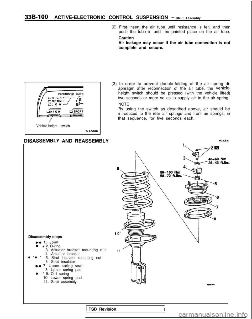
IISASSEMBLY
AND REASSEMBLY (3) In order to prevent double-folding of the air spring di-
aphragm after reconnection of the air tube, the vehicle-
height switch should be pressed (with the vehicle lifted)
two seconds or more so as to supply air to the air spring.
NOTE
By using the switch as described above, air should be
introduced to the rear air springs and front air springs, in
that sequence, for five seconds each.
Disassembly steps
,4 1. Joint
l + 2. O-ring 3. Actuator bracket mounting nut
4. Actuator bracket
l * l *5. Strut insulator mounting nut
6. Strut insulator
*+ 7. Upper spring seat 8. Upper spring pad
l * 9. Coil spring
10. Lower spring pad
11. Strut assembly
n
10
’
11 MULE-C
80-100 Nm
1 TSB RevisionI
Page 1042 of 1273

ACTIVE-ELECTRONIC CONTROL SUSPENSION - f:::,%tmb’y’ 33B-103
pF&O-rin
g
81210311
2. INSTALLATION OF O-RING/l. JOINT
Apply a coating of rubber grease to the O-ring, install it tothe joint, and then install to the piston rod.
LOWER ARM
REMOVAL AND INSTALLATION .
35-45 Nm
25-33
ft.lbs.
.-- ~~69-87 .ft.lbs.*
eLII-uu. . ..“a. 80-100
Nni*
1.
35-45 Nm 17
'
- /I MJJNA-A
58-72
ft.lbs.* 9
---. .- ..__.
SO-100 Nm12A0316
1058-72ft.lbs.
\ 17-26 Nm
12-18 ft.lbs.
lZA0230
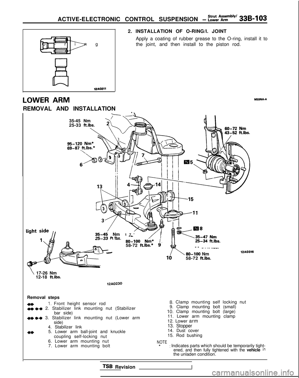
Removal steps
4*1. Front height sensor rod+e I)+ 2. Stabilizer link mounting nut (Stabilizer
bar side)
+e I)* 3. Stabilizer link mounting nut (Lower armside)
4. Stabilizer link
4*5. Lower arm ball-joint and knuckle
coupling self-locking nut
6. Lower arm mounting nut 7. Lower arm mounting bolt
8. Clamp mounting self locking nut
9. Clamp mounting bolt (small)
10. Clamp mounting bolt (large)
11. Lower arm mounting clamp
12. Lower arm
13. Stopper14. Dust cover
15. Rod bushing
NOTE*: Indicates parts which should be temporarily tight-ened, and then fully tightened with the vehicle inthe unladen condition.
TSB RevisionI
Page 1043 of 1273
339-l 04 ACTIVE-ELECTRONIC CONTROL SUSPENSION - Lower Arm
SERVICE POINTS OF REMOVAL
hl33NBAC
1. REMOVAL OF FRONT HEIGHT SENSOR ROD When removing the right strut assembly and knuckleunion, always first remove the lower arm’and
front height
sensor rod union.
yz--q--o .-L
T Front height sensor
lzAm66
12RO258
2./3. REMOVAL OF STABILIZER LINK MOUNTING NUT
Use wrench or similar tool to secure the ball stud part at
both ends of the stabilizer link, and then remove the nut.
5. REMOVAL OF LOWER ARM BALL JOINT Using the special tool, disconnect the lower arm ball joint
from the knuckle.
NOTE
(1) Always tie the cord of the special tool to the nearby
part.
(2) Loosen the nut but do not remove it.
INSPECTION
l Check the lower arm for bend or breakage. l Check the clamp for deterioration or damage.
l Check the bushing for wear and deterioration.
l Check the ball joint dust cover for cracks.
l Check all bolts for condition and straightness.
TSB Revision
Page 1049 of 1273
33B-110 ACTIVE-ELECTRONIC CONTROL SUSPENSION - i=ttbborber
SHOCK ABSORBER ASSEMBLYhl33MA-A[EMOVAL
AND INSTALLATION
1989 models
40-50 Nm
29-36 ft.lbs.
Removal
l *
l *
8-10 Nm
steps
1.Air tube2.O-ring3.Bush4.Actuator connector5.Actuator6. Rear height sensor rod
6
17-26 Nm 9127 ft.lbs;.i
1990 modelsz??
4.8-7.2 Nm
4-5 ftlbs.
\
6 80-100
Nm*
58-72
ft.lbs.*
7. Shock at%orber
upper mounting nuts
8. Shock absorber lower mounting bolts
9. Shock absorber assemblyWA0331
NOTE *: Points marked with an asterisk should first
be tightened
provisionally, then tightened fully when the vehicle is
empty.
SERVICE POINTS OF REMOVALm33hlsN
9. REMOVAL OF SHOCK ABSORBER ASSEMBLY
(1) Jack up the torsional axle and arm assembly and keep it lifted up to some degree.
Caution
1.Always insert a wooden block between the jack receptacle and the axle beam and place the jack
at the centre of the axle beam.
2. Make sure that the jack does not contact the lateral rod.
TSB Revision
Page 1050 of 1273

Shock AbsorberACTIVE-ELECTRONIC CONTROL SUSPENSION - Assembly339-111
(2) Remove the shock absorber upper mounting nuts andthe lower mounting bolts, and then remove the shock
absorber assembly.
Apply rubber greaseI
Air tubeabsorber assembly side 12A0327
Vehicle-height switch
741IOO08INSPECTION
M33McA8
CHECKING FOR SHOCK ABSORBER ASSEMBLY AIR LEAK-
AGE
For information concerning checking for air leakage of the
shock absorber assembly, refer to the section concerning the
strut assembly
(P.33B-98.)
CHECKING ACTUATOR
For information concerning the checking of the actuator, refer
to the troubleshooting guide and the service adjustment procedures section.
SERVICE POINTS OF INSTALLATION
M33MEAF
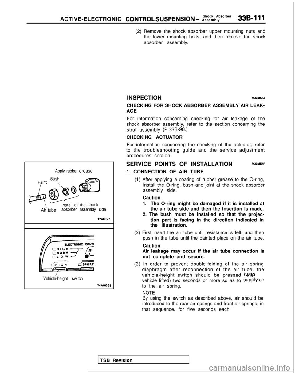
1. CONNECTION OF AIR TUBE (1) After applying a coating of rubber grease to the O-ring, install the O-ring, bush and joint at the shock absorber
assembly side.
Caution
1.The O-ring might be damaged if it is installed at
the air tube side and then the insertion is made.
2. The bush must be installed so that the projec-
tion part is facing in the direction indicated in
the illustration.
(2) First insert the air tube until resistance is felt, and then push in the tube until the painted place on the air tube.
Caution
Air leakage may occur if the air tube connection is
not complete and secure.
(3) In order to prevent double-folding of the air spring diaphragm after reconnection of the air tube. the
vehicle-height switch should be pressed (wrth the
vehicle lifted) two seconds or more so as to
Supply air
to the air spring.
NOTE
By using the switch as described above, air should be
introduced to the rear air springs and front air springs, in
that sequence, for five seconds each.
TSB Revision
Page 1054 of 1273
ACTIVE-ELECTRONIC CONTROL SUSPENSION - ~~%f;pension 33B-115
Removal
8-10 Nm
loo-120 Nm*72-87 ftlbs.’
steps
l * 11.Air tube12.Joint13.O-ring14.Bush15.Actuator connector
40-50 Nm
29-36
fi*‘v’g
SO-100
Nm*
58-72 ft.lbs.*
I
18
12AO337
16.Actuator17.Rear heiaht sensor rod mounting bolt (1989 models)
::**+*
17-l.Rear height sensor rod mounting nut
(From 1990 models)18.Lateral rod mounting bolt (body side)
19.Shock absorber upper mounting nuts20.Trailling arm mounting bolts21. Rear suspension assembly
NOTE *: Points marked with an asterisk shoud first be tightened
provisionally, then tightened fully when the vehicle is
empty.
1989 models
-From 1990 models
17-26 Nm12-19 ftlbs. 17
12AoG37
SERVICE POINTS OF REMOVAL
M33GBBE
18. REMOVAL OF LATERAL ROD MOUNTING BOLT (BODY SIDE)
(1) Remove the lateral rod from the body.
(2) Secure and hold the lateral rod to the axle beam with wire, etc.
TSB Revision
Page 1056 of 1273
ACTIVE-ELECTRONIC CONTROL SUSPENSION - ii%%;%% god 336417
12AOO88
LATERAL ROD
REMOVAL AND INS
TALLATION
i
80-100
Nm*
‘3J@a-
-
58-72 ft.lbs.*
6. INSTALLATION OF THE FLANGE NUT
After tightening the flange nut, align with the indentationin the spindle, and crimp.
MBJUA-A
6’ rrom IJJU mooers1989 models
9-14Nms 7v7-10 ft.lbs.12A0602
Removal steps
*I)111.Rear height sensor rod mounting bolt (1989 models)
Rear height sensor rod mounting nut (From 1990 models)
l
+ 2.Rear height sensor bracket mounting
bolt
3.Rear height sensor bracket B4.Rear heigh sensor bracket A
::Spacer Lateral rod mounting bolt (body side)
++ 7. Lateral rod mounting bolt (axle beamNOTEside)+: Points marked with an asterisk should first be tightenedLateral rod
provisionally, then tightened fully when the vehicle is9.Lateral rod bushingempw.
TSB Revisio
n
I