1989 FORD FIESTA fuel pressure
[x] Cancel search: fuel pressurePage 211 of 296
Front wheel toe setting -
checking and adjustment
2Due to the special measuring equipment
necessary to accurately check the wheel
alignment, and the skill required to use it
properly, checking and adjustment is best left
to a Ford dealer or similar expert. Note that
most tyre-fitting shops now possess
sophisticated checking equipment. The
following is provided as a guide, should the
owner decide to carry out a DIY check.
3 The front wheel toe setting is checked by
measuring the distance between the front and
rear inside edges of the roadwheel rims.
Proprietary toe measurement gauges are
available from motor accessory shops.
Adjustment is made by screwing the track
rods in or out of their track rod end balljoints,
to alter the effective length of the track rod
assemblies.
4 For accurate checking, the vehicle must
be at the kerb weight, ie unladen and with a
full tank of fuel.
5 Before starting work, check the tyre
pressures and tread wear, the condition of the
hub bearings, the steering wheel free play,
and the condition of the front suspension
components (see Chapter 1). Correct any
faults found.
6 Park the vehicle on level ground, check that
the front roadwheels are in the straight-ahead
position, then rock the rear and front ends to settle the suspension. Release the handbrake,
and roll the vehicle backwards 1 metre, then
forwards again, to relieve any stresses in the
steering and suspension components.
7
Measure the distance between the front
edges of the wheel rims and the rear edges of
the rims. Subtract the smallest measurement
from the largest, and check that the result is
within the specified range.
8 If adjustment is necessary, apply the
handbrake, then jack up the front of the
vehicle and support it securely on axle stands
(see “Jacking and Vehicle Support” ). Turn the
steering wheel onto full-left lock, and record
the number of exposed threads on the right-
hand track rod. Now turn the steering onto
full-right lock, and record the number of
threads on the left-hand side. If there are the
same number of threads visible on both sides,
then subsequent adjustment should be made
equally on both sides. If there are more
threads visible on one side than the other, it
will be necessary to compensate for this
during adjustment. Note:It is most important
that after adjustment, the same number of
threads are visible on each track rod.
9 First clean the track rod end; if they are
corroded, apply penetrating fluid before
starting adjustment. Release the rubber gaiter
outboard clips (where necessary), and peel
back the gaiter; apply a smear of grease to
the inside of the gaiter, so that both are free, and will not be twisted or strained as their
respective track rods are rotated.
10
Use a straight-edge and a scriber or
similar to mark the relationship of each track
rod to its track rod end balljoint, then, holding
each track rod in turn, unscrew its locknut
fully.
11 Alter the length of the track rods, bearing
in mind the note made in paragraph 8. Screw
them into or out of the track rod end balljoints,
rotating the track rods using a self-grip
wrench. Shortening the track rods (screwing
them into their track rod end balljoints) will
reduce toe-in/increase toe-out.
12 When the setting is correct, hold the track
rods and securely tighten the track rod end
balljoint locknuts. Count the exposed threads
to check the length of both track rods. If they
are not the same, then the adjustment has not
been made equally, and problems will be
encountered with tyre scrubbing in turns;
also, the steering wheel spokes will no longer
be horizontal when the wheels are in the
straight-ahead position.
13 If the track rod lengths are the same, lower
the vehicle to the ground and re-check the
toe setting; re-adjust if necessary. When the
setting is correct, securely tighten the track rod
end balljoint locknuts. Ensure that the rubber
gaiters are seated correctly, and are not
twisted or strained, and secure them in position
with new retaining clips (where necessary).
10•18 Suspension and steering
1595Ford Fiesta Remakeprocarmanuals.com
http://vnx.su
Page 244 of 296
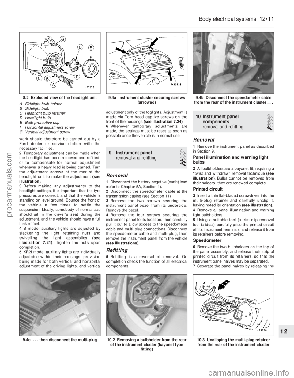
work should therefore be carried out by a
Ford dealer or service station with the
necessary facilities.
2Temporary adjustment can be made when
the headlight has been removed and refitted,
or to compensate for normal adjustment
whenever a heavy load is being carried. Turn
the adjustment screws at the rear of the
headlight unit to make the adjustment (see
illustration) .
3 Before making any adjustments to the
headlight settings, it is important that the tyre
pressures are correct, and that the vehicle is
standing on level ground. Bounce the front of
the vehicle a few times to settle the
suspension. Ideally, somebody of normal size
should sit in the driver’s seat during the
adjustment, and the vehicle should have a full
tank of fuel.
4 S model auxiliary lights are adjusted by
slackening the light retaining nuts and
swivelling the light assemblies (see
illustration 7.21) . Tighten the nuts upon
completion.
5 XR2i model auxiliary lights are individually
adjustable within their housings, provision
being made for both vertical and horizontal
adjustment of the driving lights, and vertical adjustment only of the foglights. Adjustment is
made via Torx-head captive screws on the
front of the housings
(see illustration 7.24) .
6 Whenever temporary adjustments are
made, the settings must be reset as soon as
possible once the vehicle is in normal use.
9 Instrument panel -
removal and refitting
2
Removal
1 Disconnect the battery negative (earth) lead
(refer to Chapter 5A, Section 1).
2 Disconnect the speedometer cable at the
transmission casing (see Section 11).
3 Remove the two screws securing the
instrument panel bezel from its underside.
Remove the bezel.
4 Remove the four screws securing the
instrument panel to its location, then carefully
pull it out to allow access to the speedometer
cable and multi-plug connections. Disconnect
the speedometer cable and multi-plug, then
remove the instrument panel from the vehicle
(see illustrations) .
Refitting
5Refitting is a reversal of removal. On
completion check the function of all electrical
components.
10 Instrument panel
components -
removal and refitting
1
Removal
1 Remove the instrument panel as described
in Section 9.
Panel illumination and warning light
bulbs
2 All bulbholders are a bayonet fit, requiring a
“twist and withdraw” removal technique (see
illustration) . Bulbs cannot be removed from
their holders -they are renewed complete.
Printed circuit
3 Insert a thin flat-bladed screwdriver into the
multi-plug retainer and carefully unclip it,
having noted its orientation (see illustration).
4 Remove all panel illumination and warning
light bulbholders.
5 Using a suitable tool (a trim clip removal
tool is ideal), carefully prise the printed circuit
off its instrument terminals, and release it from
its retainers before removing.
Speedometer
6 Remove the two bulbholders on the top of
the panel assembly, and release their strip of
printed circuit from its retainers, so that the
instrument panel halves may be separated.
7 Separate the panel halves by releasing the
Body electrical systems 12•11
9.4b Disconnect the speedometer cable
from the rear of the instrument cluster . . .9.4a Instrument cluster securing screws (arrowed)8.2 Exploded view of the headlight unit
A Sidelight bulb holder
B Sidelight bulb
C Headlight bulb retainer
D Headlight bulb
E Bulb protective cap
F Horizontal adjustment screw
G Vertical adjustment screw
10.3 Unclipping the multi-plug retainer from the rear of the instrument cluster10.2 Removing a bulbholder from the rear of the instrument cluster (bayonet type
fitting)9.4c . . . then disconnect the multi-plug
12
1595Ford Fiesta Remakeprocarmanuals.com
http://vnx.su
Page 272 of 296

REF•6Conversion Factors
1595 Ford Fiesta Remake
Length (distance)
Inches (in)x 25.4 = Millimetres (mm) x 0.0394 = Inches (in)
Feet (ft) x 0.305 = Metres (m) x 3.281 = Feet (ft)
Miles x 1.609 = Kilometres (km) x 0.621 = Miles
Volume (capacity)
Cubic inches (cu in; in3)x 16.387 = Cubic centimetres (cc; cm3) x 0.061 = Cubic inches (cu in; in3)
Imperial pints (Imp pt) x 0.568 = Litres (l) x 1.76 = Imperial pints (Imp pt)
Imperial quarts (Imp qt) x 1.137 = Litres (l) x 0.88 = Imperial quarts (Imp qt)
Imperial quarts (Imp qt) x 1.201 = US quarts (US qt) x 0.833 = Imperial quarts (Imp qt)
US quarts (US qt) x 0.946 = Litres (l) x 1.057 = US quarts (US qt)
Imperial gallons (Imp gal) x 4.546 = Litres (l) x 0.22 = Imperial gallons (Imp gal)
Imperial gallons (Imp gal) x 1.201 = US gallons (US gal) x 0.833 = Imperial gallons (Imp gal)
US gallons (US gal) x 3.785 = Litres (l) x 0.264 = US gallons (US gal)
Mass (weight)
Ounces (oz)x 28.35 = Grams (g) x 0.035 = Ounces (oz)
Pounds (lb) x 0.454 = Kilograms (kg) x 2.205 = Pounds (lb)
Force
Ounces-force (ozf; oz)x 0.278 = Newtons (N) x 3.6 = Ounces-force (ozf; oz)
Pounds-force (lbf; lb) x 4.448 = Newtons (N) x 0.225 = Pounds-force (lbf; lb)
Newtons (N) x 0.1 = Kilograms-force (kgf; kg) x 9.81 = Newtons (N)
Pressure
Pounds-force per square inch x 0.070 = Kilograms-force per square x 14.223 = Pounds-force per square inch
(psi; lbf/in2; lb/in2)centimetre (kgf/cm2; kg/cm2)(psi; lbf/in2; lb/in2)
Pounds-force per square inch x 0.068 = Atmospheres (atm) x 14.696 = Pounds-force per square inch
(psi; lbf/in
2; lb/in2) (psi; lbf/in2; lb/in2)
Pounds-force per square inch x 0.069 = Bars x 14.5 = Pounds-force per square inch
(psi; lbf/in
2; lb/in2) (psi; lbf/in2; lb/in2)
Pounds-force per square inch x 6.895 = Kilopascals (kPa) x 0.145 = Pounds-force per square inch
(psi; lbf/in
2; lb/in2) (psi; lbf/in2; lb/in2)
Kilopascals (kPa) x 0.01 = Kilograms-force per square x 98.1 = Kilopascals (kPa)
centimetre (kgf/cm
2; kg/cm2)
Millibar (mbar) x 100 = Pascals (Pa) x 0.01 = Millibar (mbar)
Millibar (mbar) x 0.0145 = Pounds-force per square inch x 68.947 = Millibar (mbar)
(psi; lbf/in
2; lb/in2)
Millibar (mbar) x 0.75 = Millimetres of mercury (mmHg) x 1.333 = Millibar (mbar)
Millibar (mbar) x 0.401 = Inches of water (inH
2O) x 2.491 = Millibar (mbar)
Millimetres of mercury (mmHg) x 0.535 = Inches of water (inH
2O) x 1.868 = Millimetres of mercury (mmHg)
Inches of water (inH
2O) x 0.036 = Pounds-force per square inch x 27.68 = Inches of water (inH2O)
(psi; lbf/in2; lb/in2)
Torque (moment of force)
Pounds-force inches x 1.152 = Kilograms-force centimetre x 0.868 = Pounds-force inches
(lbf in; lb in) (kgf cm; kg cm)(lbf in; lb in)
Pounds-force inches x 0.113 = Newton metres (Nm) x 8.85 = Pounds-force inches
(lbf in; lb in) (lbf in; lb in)
Pounds-force inches x 0.083 = Pounds-force feet (lbf ft; lb ft) x 12 =Pounds-force inches
(lbf in; lb in) (lbf in; lb in)
Pounds-force feet (lbf ft; lb ft) x 0.138 = Kilograms-force metres x 7.233 = Pounds-force feet (lbf ft; lb ft) (kgf m; kg m)
Pounds-force feet (lbf ft; lb ft) x 1.356 = Newton metres (Nm) x 0.738 = Pounds-force feet (lbf ft; lb ft)
Newton metres (Nm) x 0.102 = Kilograms-force metres x 9.804 = Newton metres (Nm)
(kgf m; kg m)
Power
Horsepower (hp) x 745.7 = Watts (W) x 0.0013 = Horsepower (hp)
Velocity (speed)
Miles per hour (miles/hr; mph) x 1.609 = Kilometres per hour (km/hr; kph) x 0.621 = Miles per hour (miles/hr; mph)
Fuel consumption*
Miles per gallon (mpg)x 0.354 = Kilometres per litre (km/l) x 2.825 = Miles per gallon (mpg)
Temperature
Degrees Fahrenheit = (°C x 1.8) + 32 Degrees Celsius (Degrees Centigrade; °C) = (°F - 32) x 0.56
* It is common practice to convert from miles per gallon (mpg) to litr\
es/100 kilometres (l/100km), where mpg x l/100 km = 282
procarmanuals.com
http://vnx.su
Page 280 of 296
The vehicle owner who does his or her own
maintenance according to the recommended
service schedules should not have to use this
section of the manual very often. Modern
component reliability is such that, provided
those items subject to wear or deterioration
are inspected or renewed at the specified
intervals, sudden failure is comparatively rare.
Faults do not usually just happen as a result of
sudden failure, but develop over a period of
time. Major mechanical failures in particular are usually preceded by characteristic
symptoms over hundreds or even thousands
of miles. Those components which do
occasionally fail without warning are often
small and easily carried in the vehicle.
With any fault-finding, the first step is to
decide where to begin investigations.
Sometimes this is obvious, but on other
occasions, a little detective work will be
necessary. The owner who makes half a
dozen haphazard adjustments or replacements may be successful in curing a
fault (or its symptoms), but will be none the
wiser if the fault recurs, and ultimately may
have spent more time and money than was
necessary. A calm and logical approach will
be found to be more satisfactory in the long
run. Always take into account any warning
signs or abnormalities that may have been
noticed in the period preceding the fault -
power loss, high or low gauge readings,
unusual smells, etc - and remember that
Engine
m
m
Engine backfires
m
m Engine difficult to start when cold
m
m Engine difficult to start when hot
m
m Engine fails to rotate when attempting to start
m
m Engine hesitates on acceleration
m
m Engine idles erratically
m
m Engine lacks power
m
m Engine misfires at idle speed
m
m Engine misfires throughout the driving speed range
m
m Engine noises
m
m Engine rotates, but will not start
m
m Engine runs-on after switching off
m
m Engine stalls
m
m Engine starts, but stops immediately
m
m Oil pressure warning light illuminated with engine running
m
m Starter motor noisy or excessively-rough in engagement
Cooling system
m
mCorrosion
m
m External coolant leakage
m
m Internal coolant leakage
m
m Overcooling
m
m Overheating
Fuel and exhaust systems
m
mExcessive fuel consumption
m
m Excessive noise or fumes from exhaust system
m
m Fuel leakage and/or fuel odour
Clutch
m
mClutch fails to disengage (unable to select gears)
m
m Clutch slips (engine speed increases, with no increase in vehicle
speed)
m m Judder as clutch is engaged
m
m Noise when depressing or releasing clutch pedal
m
m Pedal travels to floor - no pressure or very little resistance
Manual transmission
m
mJumps out of gear
m
m Lubricant leaks
m
m Noisy in neutral with engine running
m
m Noisy in one particular gear
m
m Vibration
Automatic transmission
m
mEngine will not start in any gear, or starts in gears other than Park
or Neutral
m m Fluid leakage
m
m General gear selection problems
m
m Transmission fluid brown, or has burned smell
m
m Transmission slips, shifts roughly, is noisy, or has no drive in
forward or reverse gears
m m Transmission will not downshift (kickdown) with accelerator fully
depressed
Driveshafts
m mClicking or knocking noise on turns (at slow speed on full-lock)
m
m Vibration when accelerating or decelerating
Braking system
m
mBrake pedal feels spongy when depressed
m
m Brakes binding
m
m Excessive brake pedal effort required to stop vehicle
m
m Excessive brake pedal travel
m
m Judder felt through brake pedal or steering wheel when braking
m
m Noise (grinding or high-pitched squeal) when brakes applied
m
m Rear wheels locking under normal braking
m
m Vehicle pulls to one side under braking
Suspension and steering systems
m
mExcessive pitching and/or rolling around corners, or during
braking
m m Excessive play in steering
m
m Excessively-stiff steering
m
m Lack of power assistance
m
m Tyre wear excessive
m
m Vehicle pulls to one side
m
m Wandering or general instability
m
m Wheel wobble and vibration
Electrical system
m
mBattery will not hold a charge for more than a few days
m
m Electric windows inoperative, or unsatisfactory in operation
m
m Horn inoperative, or unsatisfactory in operation
m
m Ignition warning light fails to come on
m
m Ignition warning light remains illuminated with engine running
m
m Instrument readings inaccurate or erratic
m
m Lights inoperative
m
m Windscreen/tailgate washers inoperative, or unsatisfactory in
operation
m m Windscreen/tailgate wipers inoperative, or unsatisfactory in
operation
REF•14Fault finding
1595 Ford Fiesta Remake
Introduction
procarmanuals.com
http://vnx.su
Page 281 of 296
1595 Ford Fiesta Remake
failure of components such as fuses or spark
plugs may only be pointers to some
underlying fault.
The pages which follow provide an easy
reference guide to the more common
problems which may occur during the
operation of the vehicle. These problems and
their possible causes are grouped under
headings denoting various components or
systems, such as Engine, Cooling system,
etc. The Chapter and/or Section which deals
with the problem is also shown in brackets.
Whatever the fault, certain basic principles
apply. These are as follows:
Verify the fault . This is simply a matter of
being sure that you know what the symptoms are before starting work. This is particularly
important if you are investigating a fault for
someone else, who may not have described it
very accurately.
Don’t overlook the obvious . For example, if
the vehicle won’t start, is there petrol in the
tank? (Don’t take anyone else’s word on this
particular point, and don’t trust the fuel gauge
either!) If an electrical fault is indicated, look
for loose or broken wires before digging out
the test gear. Cure the disease, not the symptom .
Substituting a flat battery with a fully-charged
one will get you off the hard shoulder, but if
the underlying cause is not attended to, the
new battery will go the same way. Similarly, changing oil-fouled spark plugs for a new set
will get you moving again, but remember that
the reason for the fouling (if it wasn’t simply an
incorrect grade of plug) will have to be
established and corrected.
Don’t take anything for granted . Particularly,
don’t forget that a “new” component may
itself be defective (especially if it’s been
rattling around in the boot for months), and
don’t leave components out of a fault
diagnosis sequence just because they are
new or recently fitted. When you do finally
diagnose a difficult fault, you’ll probably
realise that all the evidence was there from
the start.
Fault findingREF•15
REF
Engine
Engine fails to rotate when attempting to start
m
m Battery terminal connections loose or corroded (Chapter 5A).
m
m Battery discharged or faulty (Chapter 5A).
m
m Broken, loose or disconnected wiring in the starting circuit
(Chapter 5A).
m m Defective starter solenoid or switch (Chapter 5A).
m
m Defective starter motor (Chapter 5A).
m
m Flywheel ring gear or starter pinion teeth loose or broken
(Chapters 2A, 2B, 2C or 5A).
m m Engine earth strap broken or disconnected (Chapter 5A).
m
m Automatic transmission not in Park/Neutral position, or starter
inhibitor switch faulty (Chapter 7B).
Engine rotates, but will not start
m mFuel tank empty.
m
m Battery discharged (engine rotates slowly) (Chapter 5A).
m
m Battery terminal connections loose or corroded (Chapter 5A).
m
m Ignition components damp or damaged (Chapters 1 and 5B).
m
m Broken, loose or disconnected wiring in the ignition circuit
(Chapters 1 and 5B).
m m Worn, faulty or incorrectly-gapped spark plugs (Chapter 1).
m
m Major mechanical failure (eg camshaft drive) (Chapters 2A, 2B
or 2C).
Engine difficult to start when cold
m mBattery discharged (Chapter 5A).
m
m Battery terminal connections loose or corroded (Chapter 5A).
m
m Worn, faulty or incorrectly-gapped spark plugs (Chapter 1).
m
m Other ignition system fault (Chapters 1 and 5B).
m
m Engine management system fault (Chapters 1, 4A, 4B, 4C, 4D, 4E
or 5B).
m m Low cylinder compressions (Chapters 2A, 2B or 2C).
Engine difficult to start when hot
m
mAir filter element dirty or clogged (Chapter 1).
m
m Engine management system fault (Chapters 1, 4A, 4B, 4C, 4D, 4E
or 5B).
m m Low cylinder compressions (Chapters 2A, 2B or 2C).
m
m Faulty hydraulic tappet(s) (Chapters 2B or 2C).
Starter motor noisy or excessively-rough in
engagement
m mFlywheel ring gear or starter pinion teeth loose or broken
(Chapters 2A, 2B, 2C or 5A).
m m Starter motor mounting bolts loose or missing (Chapter 5A).
m
m Starter motor internal components worn or damaged (Chapter 5A).
Engine starts but stops immediately
m
mLoose or faulty electrical connections in the ignition circuit
(Chapters 1 and 5B).
m m Engine management system fault (Chapters 1, 4A, 4B, 4C, 4D, 4E
or 5B).
m m Vacuum leak at the inlet manifold (Chapters 1, 4A, 4B, 4C, 4D or 4E).
Engine idles erratically
m
mEngine management system fault (Chapters 1, 4A, 4B, 4C, 4D, 4E
or 5B).
m m Air filter element clogged (Chapter 1).
m
m Vacuum leak at the inlet manifold or associated hoses (Chap-
ters 1, 4A, 4B, 4C, 4D or 4E).
m m Worn, faulty or incorrectly-gapped spark plugs (Chapter 1).
m
m Incorrect valve clearances (Chapter 2A).
m
m Faulty hydraulic tappet(s) (Chapters 2B or 2C).
m
m Uneven or low cylinder compressions (Chapters 2A, 2B or 2C).
m
m Camshaft lobes worn (Chapters 2A, 2B or 2C).
m
m Timing chain and sprockets worn (Chapter 2A).
m
m Timing belt incorrectly-tensioned (Chapters 2B or 2C).
Engine misfires at idle speed
m
mWorn, faulty or incorrectly-gapped spark plugs (Chapter 1).
m
m Faulty spark plug HT leads (Chapter 1).
m
m Engine management system fault (Chapters 1, 4A, 4B, 4C, 4D, 4E
or 5B).
m m Vacuum leak at the inlet manifold or associated hoses (Chap-
ters 1, 4A, 4B, 4C, 4D or 4E).
m m Incorrect valve clearances (Chapter 2A).
m
m Faulty hydraulic tappet(s) (Chapters 2B or 2C).
m
m Uneven or low cylinder compressions (Chapters 2A, 2B and 2C).
m
m Disconnected, leaking or perished crankcase ventilation hoses
(Chapters 1 and 4E).
Engine misfires throughout the driving speed range
m mFuel filter choked (Chapter 1).
m
m Fuel pump faulty or delivery pressure low (Chapters 4A, 4B, 4C or 4D).\
m
m Fuel tank vent blocked or fuel pipes restricted (Chapters 4A, 4B,
4C, 4D or 4E).
m m Vacuum leak at the inlet manifold or associated hoses (Chap-
ters 1, 4A, 4B, 4C, 4D or 4E).
m m Worn, faulty or incorrectly-gapped spark plugs (Chapter 1).
m
m Faulty spark plug HT leads (Chapter 1).
m
m Faulty ignition coil (Chapter 5B).
m
m Engine management system fault (Chapters 1, 4A, 4B, 4C, 4D, 4E
or 5B).
m m Uneven or low cylinder compressions (Chapters 2A, 2B or 2C).
procarmanuals.com
http://vnx.su
Page 282 of 296
1595 Ford Fiesta Remake
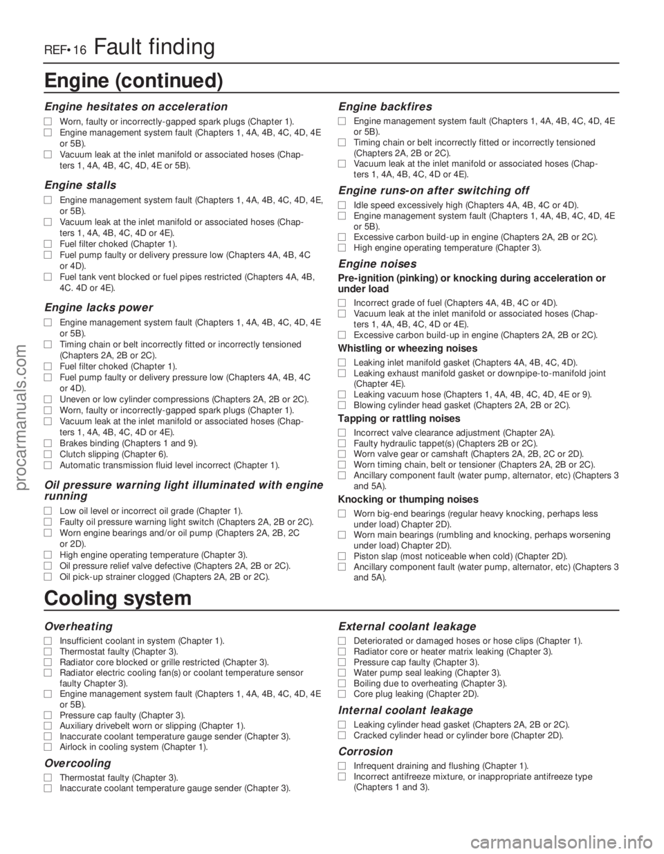
REF•16Fault finding
Cooling system
Overheating
m
mInsufficient coolant in system (Chapter 1).
m
m Thermostat faulty (Chapter 3).
m
m Radiator core blocked or grille restricted (Chapter 3).
m
m Radiator electric cooling fan(s) or coolant temperature sensor
faulty Chapter 3).
m m Engine management system fault (Chapters 1, 4A, 4B, 4C, 4D, 4E
or 5B).
m m Pressure cap faulty (Chapter 3).
m
m Auxiliary drivebelt worn or slipping (Chapter 1).
m
m Inaccurate coolant temperature gauge sender (Chapter 3).
m
m Airlock in cooling system (Chapter 1).
Overcooling
m
mThermostat faulty (Chapter 3).
m
m Inaccurate coolant temperature gauge sender (Chapter 3).
External coolant leakage
m
mDeteriorated or damaged hoses or hose clips (Chapter 1).
m
m Radiator core or heater matrix leaking (Chapter 3).
m
m Pressure cap faulty (Chapter 3).
m
m Water pump seal leaking (Chapter 3).
m
m Boiling due to overheating (Chapter 3).
m
m Core plug leaking (Chapter 2D).
Internal coolant leakage
m
mLeaking cylinder head gasket (Chapters 2A, 2B or 2C).
m
m Cracked cylinder head or cylinder bore (Chapter 2D).
Corrosion
m
mInfrequent draining and flushing (Chapter 1).
m
m Incorrect antifreeze mixture, or inappropriate antifreeze type
(Chapters 1 and 3).
Engine (continued)
Engine hesitates on acceleration
m
m Worn, faulty or incorrectly-gapped spark plugs (Chapter 1).
m
m Engine management system fault (Chapters 1, 4A, 4B, 4C, 4D, 4E
or 5B).
m m Vacuum leak at the inlet manifold or associated hoses (Chap-
ters 1, 4A, 4B, 4C, 4D, 4E or 5B).
Engine stalls
m mEngine management system fault (Chapters 1, 4A, 4B, 4C, 4D, 4E,
or 5B).
m m Vacuum leak at the inlet manifold or associated hoses (Chap-
ters 1, 4A, 4B, 4C, 4D or 4E).
m m Fuel filter choked (Chapter 1).
m
m Fuel pump faulty or delivery pressure low (Chapters 4A, 4B, 4C
or 4D).
m m Fuel tank vent blocked or fuel pipes restricted (Chapters 4A, 4B,
4C. 4D or 4E).
Engine lacks power
m mEngine management system fault (Chapters 1, 4A, 4B, 4C, 4D, 4E
or 5B).
m m Timing chain or belt incorrectly fitted or incorrectly tensioned
(Chapters 2A, 2B or 2C).
m m Fuel filter choked (Chapter 1).
m
m Fuel pump faulty or delivery pressure low (Chapters 4A, 4B, 4C
or 4D).
m m Uneven or low cylinder compressions (Chapters 2A, 2B or 2C).
m
m Worn, faulty or incorrectly-gapped spark plugs (Chapter 1).
m
m Vacuum leak at the inlet manifold or associated hoses (Chap-
ters 1, 4A, 4B, 4C, 4D or 4E).
m m Brakes binding (Chapters 1 and 9).
m
m Clutch slipping (Chapter 6).
m
m Automatic transmission fluid level incorrect (Chapter 1).
Oil pressure warning light illuminated with engine
running
m mLow oil level or incorrect oil grade (Chapter 1).
m
m Faulty oil pressure warning light switch (Chapters 2A, 2B or 2C).
m
m Worn engine bearings and/or oil pump (Chapters 2A, 2B, 2C
or 2D).
m m High engine operating temperature (Chapter 3).
m
m Oil pressure relief valve defective (Chapters 2A, 2B or 2C).
m
m Oil pick-up strainer clogged (Chapters 2A, 2B or 2C).
Engine backfires
m
mEngine management system fault (Chapters 1, 4A, 4B, 4C, 4D, 4E
or 5B).
m m Timing chain or belt incorrectly fitted or incorrectly tensioned
(Chapters 2A, 2B or 2C).
m m Vacuum leak at the inlet manifold or associated hoses (Chap-
ters 1, 4A, 4B, 4C, 4D or 4E).
Engine runs-on after switching off
m mIdle speed excessively high (Chapters 4A, 4B, 4C or 4D).
m
m Engine management system fault (Chapters 1, 4A, 4B, 4C, 4D, 4E
or 5B).
m m Excessive carbon build-up in engine (Chapters 2A, 2B or 2C).
m
m High engine operating temperature (Chapter 3).
Engine noises
Pre-ignition (pinking) or knocking during acceleration or
under load
m mIncorrect grade of fuel (Chapters 4A, 4B, 4C or 4D).
m
m Vacuum leak at the inlet manifold or associated hoses (Chap-
ters 1, 4A, 4B, 4C, 4D or 4E).
m m Excessive carbon build-up in engine (Chapters 2A, 2B or 2C).
Whistling or wheezing noises
m
mLeaking inlet manifold gasket (Chapters 4A, 4B, 4C, 4D).
m
m Leaking exhaust manifold gasket or downpipe-to-manifold joint
(Chapter 4E).
m m Leaking vacuum hose (Chapters 1, 4A, 4B, 4C, 4D, 4E or 9).
m
m Blowing cylinder head gasket (Chapters 2A, 2B or 2C).
Tapping or rattling noises
m
mIncorrect valve clearance adjustment (Chapter 2A).
m
m Faulty hydraulic tappet(s) (Chapters 2B or 2C).
m
m Worn valve gear or camshaft (Chapters 2A, 2B, 2C or 2D).
m
m Worn timing chain, belt or tensioner (Chapters 2A, 2B or 2C).
m
m Ancillary component fault (water pump, alternator, etc) (Chapters 3
and 5A).
Knocking or thumping noises
m mWorn big-end bearings (regular heavy knocking, perhaps less
under load) Chapter 2D).
m m Worn main bearings (rumbling and knocking, perhaps worsening
under load) Chapter 2D).
m m Piston slap (most noticeable when cold) (Chapter 2D).
m
m Ancillary component fault (water pump, alternator, etc) (Chapters 3
and 5A).
procarmanuals.com
http://vnx.su
Page 283 of 296
1595 Ford Fiesta Remake
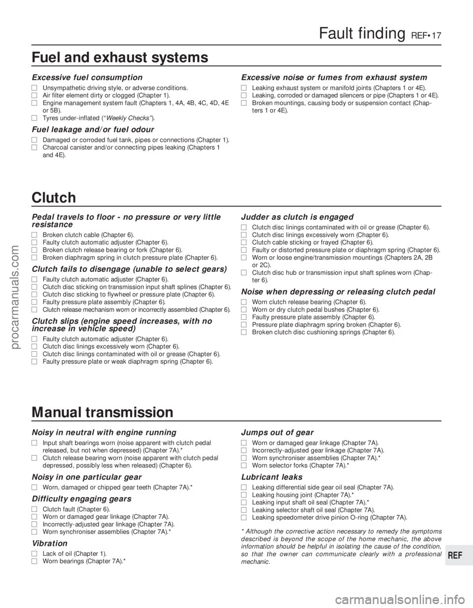
Fault findingREF•17
REF
Fuel and exhaust systems
Excessive fuel consumption
m
mUnsympathetic driving style, or adverse conditions.
m
m Air filter element dirty or clogged (Chapter 1).
m
m Engine management system fault (Chapters 1, 4A, 4B, 4C, 4D, 4E
or 5B).
m m Tyres under-inflated ( “Weekly Checks”).
Fuel leakage and/or fuel odour
m
mDamaged or corroded fuel tank, pipes or connections (Chapter 1).
m
m Charcoal canister and/or connecting pipes leaking (Chapters 1
and 4E).
Excessive noise or fumes from exhaust system
m mLeaking exhaust system or manifold joints (Chapters 1 or 4E).
m
m Leaking, corroded or damaged silencers or pipe (Chapters 1 or 4E).
m
m Broken mountings, causing body or suspension contact (Chap-
ters 1 or 4E).
Clutch
Pedal travels to floor - no pressure or very little
resistance
m mBroken clutch cable (Chapter 6).
m
m Faulty clutch automatic adjuster (Chapter 6).
m
m Broken clutch release bearing or fork (Chapter 6).
m
m Broken diaphragm spring in clutch pressure plate (Chapter 6).
Clutch fails to disengage (unable to select gears)
m
mFaulty clutch automatic adjuster (Chapter 6).
m
m Clutch disc sticking on transmission input shaft splines (Chapter 6).
m
m Clutch disc sticking to flywheel or pressure plate (Chapter 6).
m
m Faulty pressure plate assembly (Chapter 6).
m
m Clutch release mechanism worn or incorrectly assembled (Chapter 6).
Clutch slips (engine speed increases, with no
increase in vehicle speed)
m mFaulty clutch automatic adjuster (Chapter 6).
m
m Clutch disc linings excessively worn (Chapter 6).
m
m Clutch disc linings contaminated with oil or grease (Chapter 6).
m
m Faulty pressure plate or weak diaphragm spring (Chapter 6).
Judder as clutch is engaged
m
mClutch disc linings contaminated with oil or grease (Chapter 6).
m
m Clutch disc linings excessively worn (Chapter 6).
m
m Clutch cable sticking or frayed (Chapter 6).
m
m Faulty or distorted pressure plate or diaphragm spring (Chapter 6).
m
m Worn or loose engine/transmission mountings (Chapters 2A, 2B
or 2C).
m m Clutch disc hub or transmission input shaft splines worn (Chap-
ter 6).
Noise when depressing or releasing clutch pedal
m mWorn clutch release bearing (Chapter 6).
m
m Worn or dry clutch pedal bushes (Chapter 6).
m
m Faulty pressure plate assembly (Chapter 6).
m
m Pressure plate diaphragm spring broken (Chapter 6).
m
m Broken clutch disc cushioning springs (Chapter 6).
Manual transmission
Noisy in neutral with engine running
m
mInput shaft bearings worn (noise apparent with clutch pedal
released, but not when depressed) (Chapter 7A).*
m m Clutch release bearing worn (noise apparent with clutch pedal
depressed, possibly less when released) (Chapter 6).
Noisy in one particular gear
m mWorn, damaged or chipped gear teeth (Chapter 7A).*
Difficulty engaging gears
m
mClutch fault (Chapter 6).
m
m Worn or damaged gear linkage (Chapter 7A).
m
m Incorrectly-adjusted gear linkage (Chapter 7A).
m
m Worn synchroniser assemblies (Chapter 7A).*
Vibration
m
mLack of oil (Chapter 1).
m
m Worn bearings (Chapter 7A).*
Jumps out of gear
m
mWorn or damaged gear linkage (Chapter 7A).
m
m Incorrectly-adjusted gear linkage (Chapter 7A).
m
m Worn synchroniser assemblies (Chapter 7A).*
m
m Worn selector forks (Chapter 7A).*
Lubricant leaks
m
mLeaking differential side gear oil seal (Chapter 7A).
m
m Leaking housing joint (Chapter 7A).*
m
m Leaking input shaft oil seal (Chapter 7A).*
m
m Leaking selector shaft oil seal (Chapter 7A).
m
m Leaking speedometer drive pinion O-ring (Chapter 7A).
* Although the corrective action necessary to remedy the symptoms
described is beyond the scope of the home mechanic, the above
information should be helpful in isolating the cause of the condition,
so that the owner can communicate clearly with a professional
mechanic.
procarmanuals.com
http://vnx.su
Page 289 of 296
1595 Ford Fiesta Remake
Glossary of technical termsREF•23
REF
CamshaftA rotating shaft on which a series
of cam lobes operate the valve mechanisms.
The camshaft may be driven by gears, by
spr ockets and chain or by sprockets and a
belt.
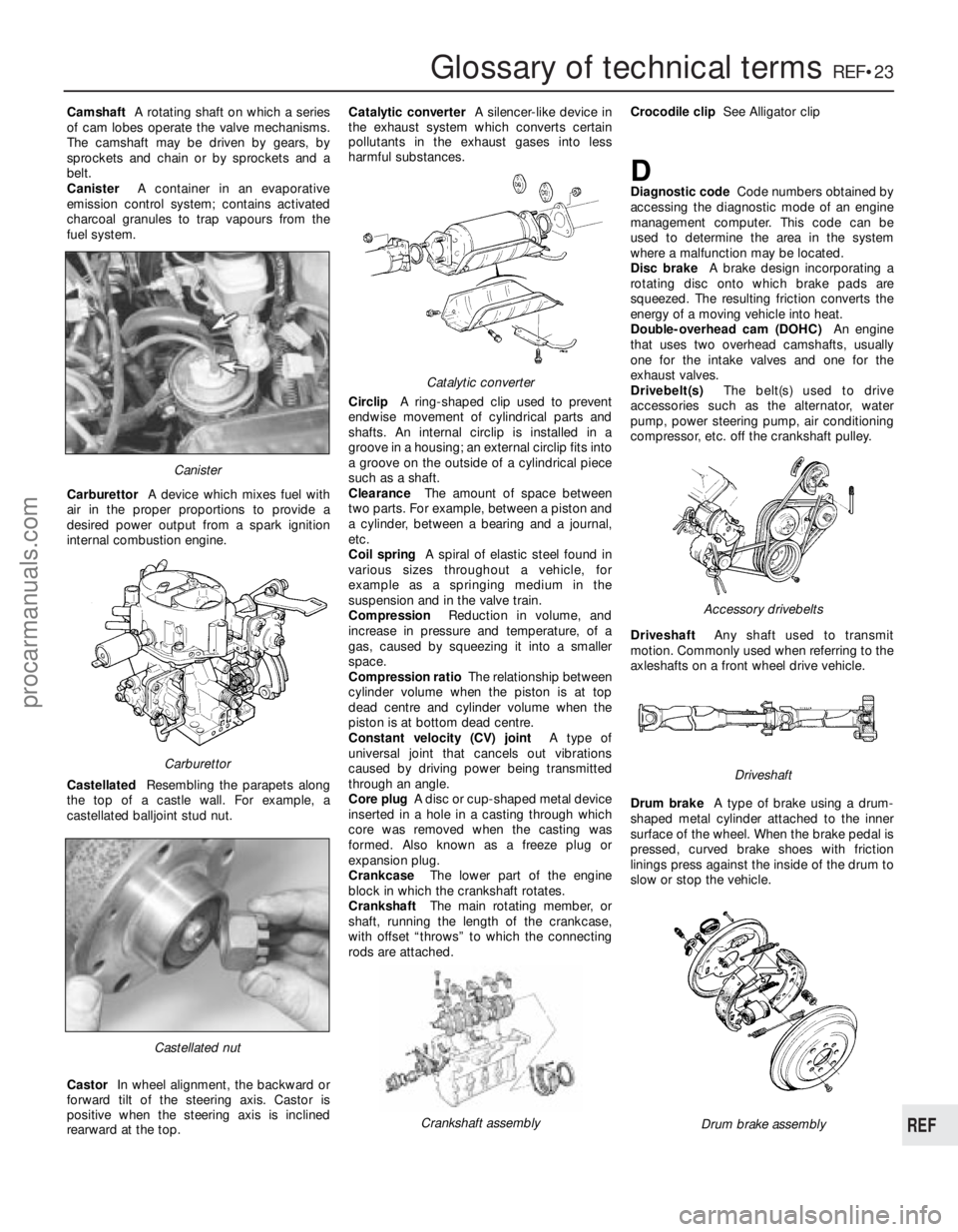
Canister A container in an evaporative
emission control system; contains activated
char coal granules to trap vapours from the
fuel system.
Carburettor A device which mixes fuel with
air in the proper proportions to provide a
desir ed power output from a spark ignition
inter nal combustion engine.
Castellated Resembling the parapets along
the top of a castle wall. For example, a
castellated balljoint stud nut.
Castor In wheel alignment, the backward or
forwar d tilt of the steering axis. Castor is
positive when the steering axis is inclined
rearwar d at the top. Catalytic converter
A silencer-like device in
the exhaust system which converts certain
pollutants in the exhaust gases into less
harmful substances.
Circlip A ring-shaped clip used to prevent
endwise movement of cylindrical parts and
shafts. An internal circlip is installed in a
gr oove in a housing; an external circlip fits into
a groove on the outside of a cylindrical piece
such as a shaft.
Clearance The amount of space between
two parts. For example, between a piston and
a cylinder, between a bearing and a journal,
etc.
Coil spring A spiral of elastic steel found in
various sizes throughout a vehicle, for
example as a springing medium in the
suspension and in the valve train.
Compression Reduction in volume, and
incr ease in pressure and temperature, of a
gas, caused by squeezing it into a smaller
space.
Compr ession ratio The relationship between
cylinder volume when the piston is at top
dead centre and cylinder volume when the
piston is at bottom dead centre.
Constant velocity (CV) joint A type of
universal joint that cancels out vibrations
caused by driving power being transmitted
thr ough an angle.
Cor e plug A disc or cup-shaped metal device
inserted in a hole in a casting through which
cor e was removed when the casting was
formed. Also known as a freeze plug or
expansion plug.
Crankcase The lower part of the engine
block in which the crankshaft rotates.
Crankshaft The main rotating member, or
shaft, running the length of the crankcase,
with offset “throws” to which the connecting
r ods are attached. Crocodile clip
See Alligator clip
DDiagnostic code Code numbers obtained by
accessing the diagnostic mode of an engine
management computer. This code can be
used to determine the area in the system
wher e a malfunction may be located.
Disc brake A brake design incorporating a
r otating disc onto which brake pads are
squeezed. The resulting friction converts the
ener gy of a moving vehicle into heat.
Double-overhead cam (DOHC) An engine
that uses two overhead camshafts, usually
one for the intake valves and one for the
exhaust valves.
Drivebelt(s) The belt(s) used to drive
accessories such as the alternator, water
pump, power steering pump, air conditioning
compressor , etc. off the crankshaft pulley.
Driveshaft Any shaft used to transmit
motion. Commonly used when referring to the
axleshafts on a front wheel drive vehicle.
Drum brake A type of brake using a drum-
shaped metal cylinder attached to the inner
surface of the wheel. When the brake pedal is
pr essed, curved brake shoes with friction
linings press against the inside of the drum to
slow or stop the vehicle.
Castellated nut
Catalytic converter
Crankshaft assembly
Carburettor
Canister
Drum brake assembly
Accessor y drivebelts
Driveshaft
procarmanuals.com
http://vnx.su