1989 FORD FIESTA heating
[x] Cancel search: heatingPage 126 of 296
This is used to refine the calculations made by
the module, when determining the correct
amount of fuel required to achieve the ideal
air/fuel mixture ratio.A throttle position sensor is mounted on the
end of the throttle valve spindle, to provide
the EEC IV module with a constantly-varying
(analogue) voltage signal corresponding to the
throttle opening. This allows the module to
register the driver’s input when determining
the amount of fuel required by the engine. Road speed is monitored by the vehicle
speed sensor. This component is a Hall-effect
generator, mounted on the transmission’s
speedometer drive. It supplies the EEC IV
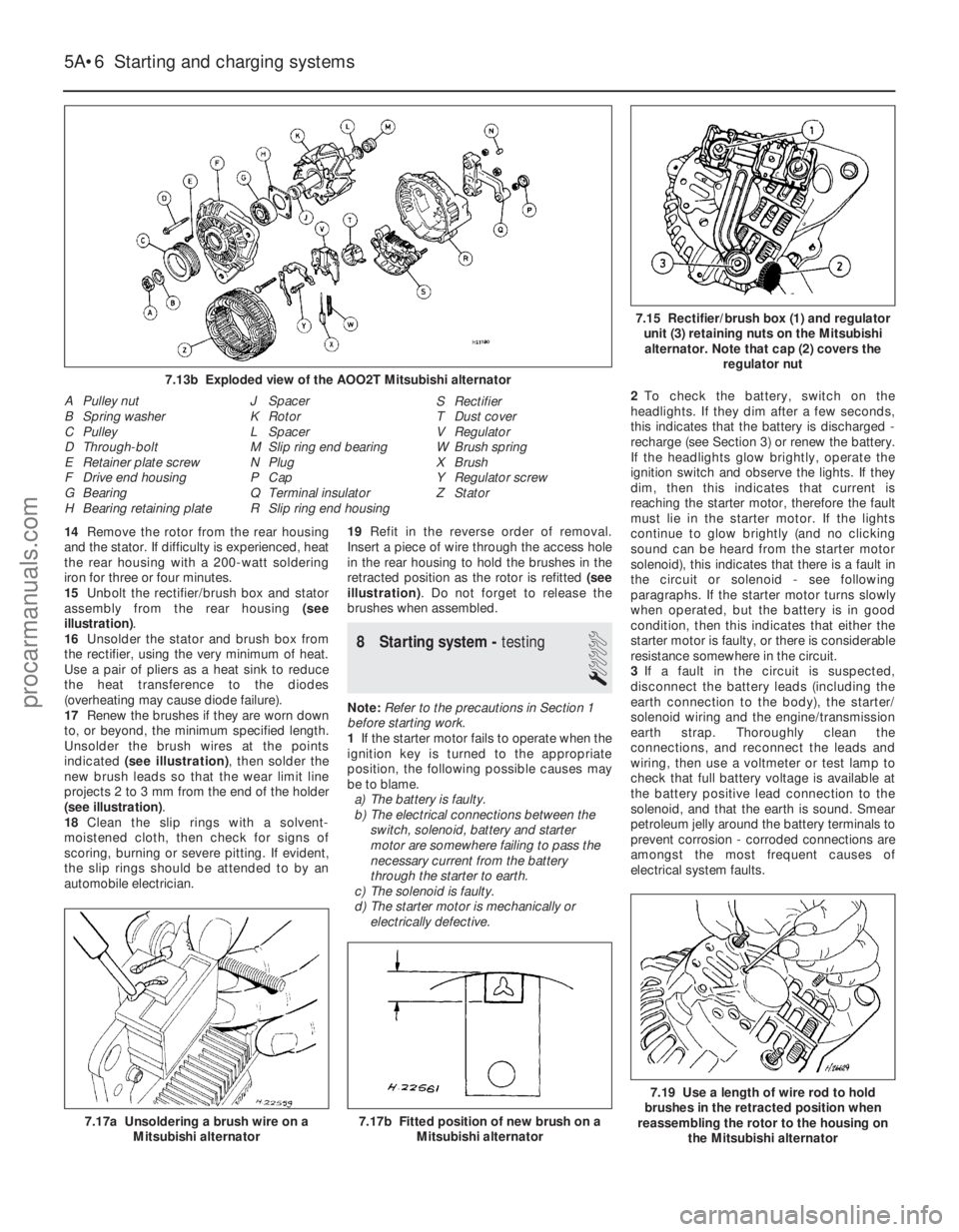
module with a series of pulses corresponding
to the vehicle’s road speed, enabling the
module to control features such as the fuel
shut-off on overrun. A manifold absolute pressure sensor
measures inlet manifold vacuum, and supplies
this information to the module for calculation
of engine load at any given throttle position. Where power steering is fitted, a pressure-
operated switch is screwed into the power
steering system’s high-pressure pipe. The
switch sends a signal to the EEC IV module to
reduce engine speed should the power
steering fluid pressure become excessively
high. Certain later engines may be fitted with a
heater in the inlet manifold. This is controlled
by the EEC IV module to ensure that, even
before the effect of the coolant heating
becomes apparent, the manifold is warmed-
up. This prevents fuel droplets condensing in
the manifold, thus improving driveability and
reducing exhaust emissions when the engine
is cold.
The oxygen sensor in the exhaust system
provides the EEC IV module with constant
feedback - “closed-loop” control - which
enables it to adjust the mixture to provide the
best possible conditions for the catalytic
converter to operate.
Precautions
Warning: Petrol is extremely
flammable - great care must be
taken when working on any part
of the fuel system. Do not
smoke or allow any naked flames or
uncovered light bulbs near the work area.
Note that gas powered domestic
appliances with pilot flames, such as
heaters, boilers and tumble dryers, also
present a fire hazard - bear this in mind if
you are working in an area where such
appliances are present. Always keep a
suitable fire extinguisher close to the work
area and familiarise yourself with its
operation before starting work. Wear eye
protection when working on fuel systems
and wash off any fuel spilt on bare skin
immediately with soap and water. Note
that fuel vapour is just as dangerous as
liquid fuel; a vessel that has just been
emptied of liquid fuel will still contain vapour and can be potentially explosive.
Petrol is a highly dangerous and volatile
liquid, and the precautions necessary
when handling it cannot be overstressed.
Many of the operations described in this
Chapter involve the disconnection of fuel
lines, which may cause an amount of fuel
spillage. Before commencing work, refer
to the above Warning and the information
in “Safety first” at the beginning of this
manual. When working with fuel system
components, pay particular attention to
cleanliness - dirt entering the fuel system
may cause blockages which will lead to
poor running.
Note: Residual pressure will remain in the fuel
lines long after the vehicle was last used,
when disconnecting any fuel line, it will be
necessary to depressurise the fuel system as
described in Section 2 .
2 Fuel system-
depressurisation
1
Note: Refer to the warning note in Section 1
before proceeding.
Warning: The following
procedure will merely relieve the
pressure in the fuel system -
remember that fuel will still be present in
the system components, and take
precautions accordingly before
disconnecting any of them.
1 The fuel system referred to in this Chapter
is defined as the fuel tank and tank-mounted
fuel pump/fuel gauge sender unit, the fuel
filter, the fuel injector, fuel pressure regulator,
and the metal pipes and flexible hoses of the
fuel lines between these components. All
these contain fuel, which will be under
pressure while the engine is running and/or
while the ignition is switched on.
2 The pressure will remain for some time after
the ignition has been switched off, and must
be relieved before any of these components is
disturbed for servicing work.
3 The simplest depressurisation method is to
disconnect the fuel pump electrical supply by
removing the fuel pump fuse (No 19) and
starting the engine; allow the engine to idle
until it dies through lack of fuel pressure. Turn
the engine over once or twice on the starter to
ensure that all pressure is released, then
switch off the ignition; do not forget to refit the
fuse when work is complete.
4 Note that, once the fuel system has been
depressurised and drained (even partially), it
will take significantly longer to restart the
engine - perhaps several seconds of cranking
- before the system is refilled and pressure
restored.
3 Fuel lines and fittings -
general information
Note: Refer to the warning note in Section 1
before proceeding.
Disconnecting and connecting
quick-release couplings
1 Quick-release couplings are employed at
many of the unions in the fuel feed and return
lines.
2 Before disconnecting any fuel system
component, relieve the residual pressure in
the system (see Section 2), and equalise tank
pressure by removing the fuel filler cap.
Warning: This procedure will
merely relieve the increased
pressure necessary for the
engine to run - remember that
fuel will still be present in the system
components, and take precautions
accordingly before disconnecting any of
them.
3 Release the protruding locking lugs on each
union, by squeezing them together and
carefully pulling the coupling apart. Use rag to
soak up any spilt fuel. Where the unions are
colour-coded, the pipes cannot be confused.
Where both unions are the same colour, note
carefully which pipe is connected to which,
and ensure that they are correctly
reconnected on refitting.
4 To reconnect one of these couplings, press
them together until the locking lugs snap into
their groove. Switch the ignition on and off
five times to pressurise the system, and check
for any sign of fuel leakage around the
disturbed coupling before attempting to start
the engine.
Checking
5 Checking procedures for the fuel lines are
included in Chapter 1.
Component renewal
6 If any damaged sections are to be renewed,
use original-equipment replacement hoses or
pipes, constructed from exactly the same
material as the section being replaced. Do not
install substitutes constructed from inferior or
inappropriate material; this could cause a fuel
leak or a fire.
7 Before detaching or disconnecting any part
of the fuel system, note the routing of all
hoses and pipes, and the orientation of all
clamps and clips. Replacement sections must
be installed in exactly the same manner.
8 Before disconnecting any part of the fuel
system, be sure to relieve the fuel system
pressure (see Section 2), and equalise tank
pressure by removing the fuel filler cap. Also
disconnect the battery negative (earth) lead -
see Chapter 5A, Section 1. Cover the fitting
being disconnected with a rag, to absorb any
fuel that may spray out.
Fuel system - central fuel injection engines 4B•3
4B
1595Ford Fiesta Remakeprocarmanuals.com
http://vnx.su
Page 153 of 296
into the engine induction system and thence
into the combustion chambers. This
arrangement eliminates any fuel mixture
control problems. The operating principles for
the system used on the Endura-E engine are
basically the same as just described with
revisions to the component locations and
hose arrangement.On CVH and PTE engines, a closed-circuit
type crankcase ventilation system is used, the
function of which is basically the same as that
described for the HCS engine type, but the
breather hose connects directly to the rocker
cover. The oil filler cap incorporates a
separate filter in certain applications. On Zetec engines, the crankcase ventilation
system main components are the oil
separator mounted on the front (radiator) side
of the cylinder block/crankcase, and the
Positive Crankcase Ventilation (PCV) valve set
in a rubber grommet in the separator’s left-
hand upper end. The associated pipework
consists of a crankcase breather pipe and two
flexible hoses connecting the PCV valve to a
union on the left-hand end of the inlet
manifold, and a crankcase breather hose
connecting the cylinder head cover to the air
cleaner assembly. A small foam filter in the air
cleaner prevents dirt from being drawn
directly into the engine.
Evaporative emissions control system
This system is fitted to minimise the escape
of unburned hydrocarbons into the
atmosphere. Fuel evaporative emissions
control systems are limited on vehicles
meeting earlier emissions regulations;
carburettor float chambers are vented
internally, whilst fuel tanks vent to atmosphere
through a combined roll-over/anti-trickle-fill
valve. On vehicles meeting the more stringent
emissions regulations, the fuel tank filler cap
is sealed, and a charcoal canister is used to
collect and store petrol vapours generated in
the tank when the vehicle is parked. When the
engine is running, the vapours are cleared
from the canister (under the control of the
EEC IV engine management module via the
canister-purge solenoid valve) into the inlet
tract, to be burned by the engine during
normal combustion. To ensure that the engine runs correctly
when it is cold and/or idling, and to protect
the catalytic converter from the effects of an
over-rich mixture, the canister-purge solenoid
valve is not opened by the EEC IV module
until the engine is fully warmed-up and
running under part-load; the solenoid valve is
then switched on and off, to allow the stored
vapour to pass into the inlet tract.
Pulse-air system
This system consists of the pulse-air
solenoid valve, the pulse-air valve itself, the
delivery tubing, a pulse-air filter, and on some
models, a check valve. The system injects
filtered air directly into the exhaust ports,
using the pressure variations in the exhaust
gases to draw air through from the filter housing; air will flow into the exhaust only
when its pressure is below atmospheric. The
pulse-air valve can allow gases to flow only
one way, so there is no risk of hot exhaust
gases flowing back into the filter.
The system’s primary function is raise
exhaust gas temperatures on start-up, thus
reducing the amount of time taken for the
catalytic converter to reach operating
temperature. Until this happens, the system
reduces emissions of unburned hydrocarbon
particles (HC) and carbon monoxide (CO) by
ensuring that a considerable proportion of
these substances remaining in the exhaust
gases after combustion are burned up, either
in the manifold itself or in the catalytic
converter.
To ensure that the system does not upset
the smooth running of the engine under
normal driving conditions, it is linked by the
pulse-air solenoid valve to the EEC IV module,
so that it only functions during engine warm-
up, when the oxygen sensor is not influencing
the fuel/air mixture ratio.
Catalytic converter
Catalytic converters have been introduced
progressively on all models in the range, to
meet the various emissions regulations.
The catalytic converter is located in the
exhaust system, and operates in conjunction
with an exhaust gas oxygen sensor to reduce
exhaust gas emissions. The catalytic
converter uses precious metals (platinum and
palladium or rhodium) as catalysts to speed
up the reaction between the pollutants and
the oxygen in the vehicle’s exhaust gases, CO
and HC being oxidised to form H
2O and CO2and (in the three-way type of catalytic
converter) NO
xbeing reduced to N2. Note :
The catalytic converter is not a filter in the
physical sense; its function is to promote a
chemical reaction, but it is not itself affected
by that reaction. The converter consists of an element (or
“substrate”) of ceramic honeycomb, coated
with a combination of precious metals in such
a way as to produce a vast surface area over
which the exhaust gases must flow; the whole
being mounted in a stainless-steel box. A
simple “oxidation” (or “two-way”) catalytic
converter can deal with CO and HC only,
while a “reduction” (or “three-way”) catalytic
converter can deal with CO, HC and NO
x.
Three-way catalytic converters are further
sub-divided into “open-loop” (or
“unregulated”) converters, which can remove
50 to 70% of pollutants and “closed-loop”
(also known as “controlled” or “regulated”)
converters, which can remove over 90% of
pollutants.
In order for a closed-loop catalytic
converter to operate effectively, the air/fuel
mixture must be very accurately controlled,
and this is achieved by measuring the oxygen
content of the exhaust gas. The oxygen
sensor transmits information on the exhaust
gas oxygen content to the EEC IV engine management module, which adjusts the
air/fuel mixture strength accordingly.
The sensor has a built-in heating element
which is controlled by the EEC IV module, in
order to bring the sensor’s tip to an efficient
operating temperature as rapidly as possible.
The sensor’s tip is sensitive to oxygen, and
sends the module a varying voltage
depending on the amount of oxygen in the
exhaust gases; if the inlet air/fuel mixture is
too rich, the sensor sends a high-voltage
signal. The voltage falls as the mixture
weakens. Peak conversion efficiency of all
major pollutants occurs if the inlet air/fuel
mixture is maintained at the chemically-
correct ratio for the complete combustion of
petrol - 14.7 parts (by weight) of air to 1 part
of fuel (the “stoichiometric” ratio). The sensor
output voltage alters in a large step at this
point, the module using the signal change as
a reference point, and correcting the inlet
air/fuel mixture accordingly by altering the fuel
injector pulse width (injector opening time). Removal and refitting procedures for
the oxygen sensor are given in Parts B, C
and D of this Chapter according to fuel
system type.
2 Exhaust system - renewal
2
Warning: Inspection and repair
of exhaust system components
should be done only after
enough time has elapsed after
driving the vehicle to allow the system
components to cool completely. This
applies particularly to the catalytic
converter, which runs at very high
temperatures. Also, when working under
the vehicle, make sure it is securely
supported on axle stands.
If the exhaust system components are
extremely corroded or rusted together, they
will probably have to be cut from the exhaust
system. The most convenient way of
accomplishing this is to have a quick-fit
exhaust repair specialist remove the corroded
sections. Alternatively, you can simply cut off
the old components with a hacksaw. If you do
decide to tackle the job at home, be sure to
wear eye protection, to protect your eyes from
metal chips, and work gloves, to protect your
hands. If the production-fit system is still
fitted, it must be cut for the service-
replacement system sections to fit. The best
way of determining the correct cutting point is
to obtain the new centre or rear section first
then, with the old system removed, lay the
two side by side on the ground. It should now
be relatively easy to determine where the old
system needs to be cut, and it can be marked
accordingly. Remember to allow for the
overlap where the two sections will plug
together.
4E•2 Exhaust and emission control systems
1595Ford Fiesta Remakeprocarmanuals.com
http://vnx.su
Page 154 of 296
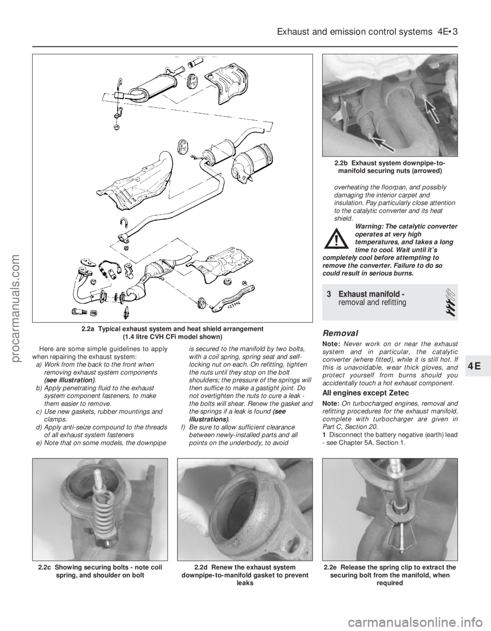
Here are some simple guidelines to apply
when repairing the exhaust system: a) Work from the back to the front when
removing exhaust system components
(see illustration) .
b) Apply penetrating fluid to the exhaust
system component fasteners, to make
them easier to remove.
c) Use new gaskets, rubber mountings and clamps.
d) Apply anti-seize compound to the threads
of all exhaust system fasteners
e) Note that on some models, the downpipe is secured to the manifold by two bolts,
with a coil spring, spring seat and self-
locking nut on each. On refitting, tighten
the nuts until they stop on the bolt
shoulders; the pressure of the springs will
then suffice to make a gastight joint. Do
not overtighten the nuts to cure a leak -
the bolts will shear. Renew the gasket and
the springs if a leak is found
(see
illustrations) .
f) Be sure to allow sufficient clearance between newly-installed parts and all
points on the underbody, to avoid overheating the floorpan, and possibly
damaging the interior carpet and
insulation. Pay particularly close attention
to the catalytic converter and its heat
shield.
Warning: The catalytic converter
operates at very high
temperatures, and takes a long
time to cool. Wait until it’s
completely cool before attempting to
remove the converter. Failure to do so
could result in serious burns.
3 Exhaust manifold - removal and refitting
3
Removal
Note: Never work on or near the exhaust
system and in particular, the catalytic
converter (where fitted), while it is still hot. If
this is unavoidable, wear thick gloves, and
protect yourself from burns should you
accidentally touch a hot exhaust component.
All engines except Zetec
Note: On turbocharged engines, removal and
refitting procedures for the exhaust manifold,
complete with turbocharger are given in
Part C, Section 20.
1 Disconnect the battery negative (earth) lead
- see Chapter 5A, Section 1.
Exhaust and emission control systems 4E•3
2.2b Exhaust system downpipe-to- manifold securing nuts (arrowed)
2.2a Typical exhaust system and heat shield arrangement (1.4 litre CVH CFi model shown)
2.2e Release the spring clip to extract thesecuring bolt from the manifold, when
required2.2d Renew the exhaust system
downpipe-to-manifold gasket to prevent
leaks2.2c Showing securing bolts - note coilspring, and shoulder on bolt
4E
1595Ford Fiesta Remakeprocarmanuals.com
http://vnx.su
Page 162 of 296
Ambient Ambient
temperature temperature
abovebelow
25°C (77°F) 25°C (77°F)
Fully-charged 1.210 to 1.230 1.270 to 1.290
70% charged 1.170 to 1.190 1.230 to 1.250
Fully-discharged 1.050 to 1.070 1.110 to 1.130
Note that the specific gravity readings
assume an electrolyte temperature of
15°C (60°F); for every 10°C (18°F) below 15°C
(60°F) subtract 0.007. For every 10°C (18°F)
above 15°C (60°F) add 0.007.
2 If the battery condition is suspect, first
check the specific gravity of electrolyte in
each cell. A variation of 0.040 or more
between any cells indicates loss of electrolyte
or deterioration of the internal plates.
3 If the specific gravity variation is 0.040 or
more, the battery should be renewed. If the
cell variation is satisfactory but the battery is
discharged, it should be charged as
described later in this Section.
Maintenance-free battery -
testing
4 In cases where a “sealed for life”
maintenance-free battery is fitted, topping-up
and testing of the electrolyte in each cell is not
possible. The condition of the battery can
therefore only be tested using a battery
condition indicator or a voltmeter.
5 If testing the battery using a voltmeter,
connect the voltmeter across the battery and
compare the result with those given in the
Specifications under “charge condition”. The
test is only accurate if the battery has not
been subjected to any kind of charge for the
previous six hours. If this is not the case,
switch on the headlights for 30 seconds, then
wait four to five minutes before testing the
battery after switching off the headlights. All
other electrical circuits must be switched off,
so check that the doors and tailgate are fully
shut when making the test.
6 If the voltage reading is less than 12.2 volts,
then the battery is discharged, whilst a
reading of 12.2 to 12.4 volts indicates a
partially discharged condition.
7 If the battery is to be charged, remove it
from the vehicle (Section 4) and charge it as
described later in this Section.
Standard and low maintenance
battery - charging
Note: The following is intended as a guide
only. Always refer to the manufacturer’s
recommendations (often printed on a label
attached to the battery) before charging a
battery.
8 Charge the battery at a rate of 3.5 to
4 amps and continue to charge the battery at
this rate until no further rise in specific gravity
is noted over a four hour period.
9 Alternatively, a trickle charger charging at
the rate of 1.5 amps can safely be used
overnight.
10 Specially rapid “boost” charges which are
claimed to restore the power of the battery in 1 to 2 hours are not recommended, as they
can cause serious damage to the battery
plates through overheating.
11
While charging the battery, note that the
temperature of the electrolyte should never
exceed 37.8°C (100°F).
Maintenance-free battery -
charging
Note: The following is intended as a guide
only. Always refer to the manufacturer’s
recommendations (often printed on a label
attached to the battery) before charging a
battery.
12 This battery type takes considerably
longer to fully recharge than the standard
type, the time taken being dependent on the
extent of discharge, but it can take anything
up to three days.
13 A constant voltage type charger is
required, to be set, when connected, to 13.9
to 14.9 volts with a charger current below
25 amps. Using this method, the battery
should be usable within three hours, giving a
voltage reading of 12.5 volts, but this is for a
partially discharged battery and, as
mentioned, full charging can take
considerably longer.
14 If the battery is to be charged from a fully
discharged state (condition reading less than
12.2 volts), have it recharged by your Ford
dealer or local automotive electrician, as the
charge rate is higher and constant supervision
during charging is necessary.
4 Battery -
removal and refitting
1
Note: Refer to the precautions in Section 1
before starting work.
Removal
1 The battery is located forward on the left-
hand side of the engine compartment, on a
platform welded to the vehicle structure.
2 Undo the retaining nut, then detach the
earth leads from the stud of the battery
negative (earth) terminal post. This is the
terminal to disconnect before working on, or
disconnecting, any electrical component on
the vehicle.
3 Pivot up the plastic cover from the positive
terminal, then unscrew the positive lead
retaining nut on the terminal. Detach the
positive lead from the terminal.
4 Release the clamp securing the battery to
its platform and remove it. Lift the battery
from its location, keeping it in an upright
position to avoid the possibility of corrosive
electrolyte spilling onto the paintwork.
5 Clean the battery terminal posts, clamps
and the battery casing. If the bulkhead is
rusted as a result of battery acid spilling onto
it, clean it thoroughly and re-paint with
reference to Chapter 1. 6
If you are renewing the battery, make sure
that you get one that’s identical, with the
same dimensions, amperage rating, cold
cranking rating, etc. Dispose of the old battery
in a responsible fashion. Most local authorities
have facilities for the collection and disposal
of such items - batteries contain sulphuric
acid and lead, and should not be simply
thrown out with the household rubbish!
Refitting
7 Refitting is a reversal of removal. Smear the
battery terminals with a petroleum-based jelly
prior to reconnecting. Always connect the
positive terminal clamp first and the negative
terminal clamp last.
5 Charging system - testing
2
Note:Refer to the precautions in Section 1
before starting work.
1 If the ignition warning light fails to
illuminate when the ignition is switched on,
first check the alternator wiring connections
for security. If satisfactory, check that the
warning light bulb has not blown, and that
the bulbholder is secure in its location in the
instrument panel. If the light still fails to
illuminate, check the continuity of the
warning light feed wire from the alternator to
the bulbholder. If all is satisfactory, the
alternator is at fault and should be renewed
or taken to an auto-electrician for testing and
repair.
2 If the ignition warning light illuminates when
the engine is running, stop the engine and
check that the drivebelt is correctly tensioned
(see Chapter 1) and that the alternator
connections are secure. If all is so far
satisfactory, have the alternator checked by
an auto-electrician for testing and repair.
3 If the alternator output is suspect even
though the warning light functions correctly,
the regulated voltage may be checked as
follows.
4 Connect a voltmeter across the battery
terminals and start the engine.
5 Increase the engine speed until the
voltmeter reading remains steady; the
reading should be approximately 13.5 to
14.6 volts.
6 Switch on as many electrical accessories
(eg, the headlights, heated rear window and
heater blower) as possible, and check that the
alternator maintains the regulated voltage at
around 13 to 14 volts.
7 If the regulated voltage is not as stated, the
fault may be due to worn brushes, weak brush
springs, a faulty voltage regulator, a faulty
diode, a severed phase winding or worn or
damaged slip rings. The alternator should be
renewed or taken to an auto-electrician for
testing and repair.
Starting and charging systems 5A•3
5A
1595Ford Fiesta Remakeprocarmanuals.com
http://vnx.su
Page 165 of 296
14Remove the rotor from the rear housing
and the stator. If difficulty is experienced, heat
the rear housing with a 200-watt soldering
iron for three or four minutes.
15 Unbolt the rectifier/brush box and stator
assembly from the rear housing (see
illustration) .
16 Unsolder the stator and brush box from
the rectifier, using the very minimum of heat.
Use a pair of pliers as a heat sink to reduce
the heat transference to the diodes
(overheating may cause diode failure).
17 Renew the brushes if they are worn down
to, or beyond, the minimum specified length.
Unsolder the brush wires at the points
indicated (see illustration) , then solder the
new brush leads so that the wear limit line
projects 2 to 3 mm from the end of the holder
(see illustration) .
18 Clean the slip rings with a solvent-
moistened cloth, then check for signs of
scoring, burning or severe pitting. If evident,
the slip rings should be attended to by an
automobile electrician. 19
Refit in the reverse order of removal.
Insert a piece of wire through the access hole
in the rear housing to hold the brushes in the
retracted position as the rotor is refitted (see
illustration) . Do not forget to release the
brushes when assembled.
8 Starting system - testing
1
Note:Refer to the precautions in Section 1
before starting work.
1 If the starter motor fails to operate when the
ignition key is turned to the appropriate
position, the following possible causes may
be to blame.
a) The battery is faulty.
b) The electrical connections between the
switch, solenoid, battery and starter
motor are somewhere failing to pass the
necessary current from the battery
through the starter to earth.
c) The solenoid is faulty.
d) The starter motor is mechanically or
electrically defective. 2
To check the battery, switch on the
headlights. If they dim after a few seconds,
this indicates that the battery is discharged -
recharge (see Section 3) or renew the battery.
If the headlights glow brightly, operate the
ignition switch and observe the lights. If they
dim, then this indicates that current is
reaching the starter motor, therefore the fault
must lie in the starter motor. If the lights
continue to glow brightly (and no clicking
sound can be heard from the starter motor
solenoid), this indicates that there is a fault in
the circuit or solenoid - see following
paragraphs. If the starter motor turns slowly
when operated, but the battery is in good
condition, then this indicates that either the
starter motor is faulty, or there is considerable
resistance somewhere in the circuit.
3 If a fault in the circuit is suspected,
disconnect the battery leads (including the
earth connection to the body), the starter/
solenoid wiring and the engine/transmission
earth strap. Thoroughly clean the
connections, and reconnect the leads and
wiring, then use a voltmeter or test lamp to
check that full battery voltage is available at
the battery positive lead connection to the
solenoid, and that the earth is sound. Smear
petroleum jelly around the battery terminals to
prevent corrosion - corroded connections are
amongst the most frequent causes of
electrical system faults.
5A•6 Starting and charging systems
7.19 Use a length of wire rod to hold
brushes in the retracted position when
reassembling the rotor to the housing on
the Mitsubishi alternator
7.17b Fitted position of new brush on a Mitsubishi alternator7.17a Unsoldering a brush wire on aMitsubishi alternator
7.15 Rectifier/brush box (1) and regulatorunit (3) retaining nuts on the Mitsubishialternator. Note that cap (2) covers the regulator nut
A Pulley nut
B Spring washer
C Pulley
D Through-bolt
E Retainer plate screw
F Drive end housing
G Bearing
H Bearing retaining plate J Spacer
K Rotor
L Spacer
M Slip ring end bearing
N Plug
P Cap
Q Terminal insulator
R Slip ring end housing S Rectifier
T Dust cover
V Regulator
W Brush spring
X Brush
Y Regulator screw
Z Stator
1595Ford Fiesta Remake
7.13b Exploded view of the AOO2T Mitsubishi alternatorprocarmanuals.com
http://vnx.su
Page 227 of 296
suitable adhesive; it is recommended that this
task be left to a Ford dealer or similar expert.
15To remove the window glass, remove their
retaining screws and withdraw the lock
assemblies, slide the front glass as far to the
rear as possible, then prise up and withdraw
the front glass guide; it will be necessary to
pull the last part of the guide from under the
glass.
16 Withdraw the vertical seal and two
support blocks from between the two glasses,
slide the seal to the front of the frame, and
withdraw it. Slide each glass in turn
to the front of the frame and withdraw it,
then prise up and withdraw the rear glass
guide.
Refitting
17 On refitting, check that the glass guides
are undamaged; renew them if necessary.
Ensure that the lock assemblies are removed
from both glasses.
18 Press the rear glass guide into place. Refit
first the rear glass, fitting it to the front of the
frame and sliding it to the rear, then the front
glass, in the same way.
19 To refit the vertical seal, sandwich it
between two strips of thin sheet metal and
install it, with its support blocks, first in the
front part of the frame, then push it into place.
This will require some effort as the glass is
reached, due to the distortion caused by the
location notch on the block. When the seal is
fully in place, withdraw the metal strips, and
check that the seal’s lips have not folded back
on themselves.
20 When refitting the front glass guide, locate
it first around the frame’s detent catch, then
slide it under the glass using soapy water as a
lubricant.
21 Refit the lock assemblies, clean the
glasses, and check the operation of the
windows and locks.
34 Windscreen and tailgate window glass -
removal and refitting
4
Note : The DIY mechanic is advised to leave
windscreen/tailgate window glass removal
and refitting to an expert. For those with the
necessary tools and equipment, the
following paragraphs are a guide to the
procedure.
Removal
1 Remove the windscreen/tailgate wiper arms
as described in Chapter 12.
2 If removing the windscreen, remove both A-
pillar trims, and release the front of the
headlining by removing the sun visors and
courtesy light. If a heated windscreen is fitted,
disconnect its electrical contacts at the
windscreen. If removing the tailgate window
glass, disconnect the wiring to the heating
element. 3
As a precautionary measure to prevent
damage to the paintwork, cover the
surrounding bodywork with an old blanket or
similar.
4 Using a suitable tool, release the
weatherseal from the top and sides of the
body aperture flange before exerting pressure
from the inside of the vehicle to remove the
assembly. It is strongly advised that an
assistant outside the vehicle is ready to
receive the glass as it is pushed out.
5 With the assembly removed from the
vehicle, detach the weatherseal from the
windscreen/tailgate glass.
Refitting
6 With reference to the procedures described
for the fixed side window glass in Section 33,
clean the weatherseal, then refit in
accordance with the rest of that Section.
7 Any trim and equipment removed during
preparation should now be refitted.
35 Sunroof panel -
removal and refitting
1
Removal
1 Open the sunroof fully using the handwheel.
2 Detach the sunroof from its rearward
mounting point by pressing in the red locking
bar on the handwheel, then raise it and
remove.
Refitting
3 To refit, engage the hinges in their
locations, in the forward edge of the sunroof
opening, then lower the sunroof. Allow the
handwheel to click into its safety lock.
4 Check that the safety lock mechanism
retains the panel securely.
5 Close the sunroof fully using the
handwheel.
36 Sunroof panel seal -
renewal
1
1 Remove the sunroof panel, as described in
Section 35, then lay the panel on a soft cloth.
2 Remove the two hinge plate assemblies
from the panel by undoing the hinge plate
retaining screws.
3 Pull the seal from the panel edge, noting the
position of its join.
4 Starting from the position of the original
join, press the seal into position, ensuring that
it sits evenly right around. Adjust as necessary
so that the ends butt tightly together.
5 Refit the two hinge plate assemblies to the
panel.
6 Refit the sunroof panel, as described in
Section 35.
37 Sunroof weatherseal -
removal and refitting
1
Removal
1 Remove the sunroof panel, as described in
Section 35.
2 Starting from the joint on the rearward
opening edge, pull the seal up and remove.
Refitting
3 Refitting is a reversal of the removal
procedure, ensuring that the weatherseal
does not deform at the corners, or split at the
joint.
38 Full-length sunroof -
general information
1 The full-length sunroof is electrically-
operated, the operating system consisting of
the motor and the roof-mounted switch. The
circuit is fed via fuses 18 and 28 from the
ignition switch; switch illumination is via
fuse 6.
2 All components are mounted in the roof of
the passenger compartment, above the
headlining at the front of the vehicle.
3 To open the sunroof, press the switch
lightly on the upper side; to close it, check
first that the opening is completely
unobstructed, and press the switch on the
lower side.
4 Maintenance is confined to checking for
freedom of action and a snug fit when shut.
Check that the seals are in good clean
condition and not scratched or damaged.
5 Owners must note the following to ensure
that the maximum trouble-free life from this
feature:
a) It is normal for the motor to slow down as
the sunroof approaches full opening.
b) If the sunroof stops before it is fully
opened in cold weather, this may be due
to the material being too hard to fold
correctly; do not force the sunroof open if
this is suspected.
c) If the material does not fold correctly on
opening at any time, close the sunroof
again, correct the folds by hand, and try
again.
d) Never open or close the sunroof with the
vehicle travelling at more than 70 mph
(120 km/h), and never allow passengers to
travel standing up or with any part of their
bodies in the opening.
e) Ensure that any collected water, snow or ice is removed from the sunroof before
opening it. Check that the deflector is
clear of water, particularly after washing
the vehicle; sponge it dry if necessary.
f) Never place heavy objects on the sunroof or its surrounds.
g) The sunroof should be cleaned frequently
11•16 Bodywork and fittings
1595Ford Fiesta Remakeprocarmanuals.com
http://vnx.su
Page 237 of 296
wiring diagrams are included at the end of this
manual.
2Before attempting to diagnose an electrical
fault, first study the appropriate wiring
diagram, to obtain a complete understanding
of the components included in the particular
circuit concerned. The possible sources of a
fault can be narrowed down by noting if other
components related to the circuit are
operating properly. If several components or
circuits fail at one time, the problem is likely to
be related to a shared fuse or earth
connection.
3 Electrical problems usually stem from
simple causes, such as loose or corroded
connections, a faulty earth connection, a
blown fuse, a melted fusible link, or a faulty
relay (refer to Section 3 for details of testing
relays). Visually inspect the condition of all
fuses, wires and connections in a problem
circuit before testing the components. Use
the wiring diagrams to determine which
terminal connections will need to be checked
in order to pinpoint the trouble-spot.
4 The basic tools required for electrical fault-
finding include a circuit tester or voltmeter (a
12-volt bulb with a set of test leads can also
be used for certain tests); an ohmmeter (to
measure resistance and check for continuity);
a battery and set of test leads; and a jumper
wire, preferably with a circuit breaker or fuse
incorporated, which can be used to bypass
suspect wires or electrical components.
Before attempting to locate a problem with
test instruments, use the wiring diagram to
determine where to make the connections.
Warning: Under no
circumstances may live
measuring instruments such as
ohmmeters, voltmeters or a bulb
and test leads be used to test any of the
air bag circuitry or components. Any
testing in these areas must be left to a
Ford dealer as there is a danger of
activating the system if the correct
procedures are not followed.
5 To find the source of an intermittent wiring
fault (usually due to a poor or dirty
connection, or damaged wiring insulation), a
“wiggle” test can be performed on the wiring.
This involves wiggling the wiring by hand to
see if the fault occurs as the wiring is moved.
It should be possible to narrow down the
source of the fault to a particular section of
wiring. This method of testing can be used in
conjunction with any of the tests described in
the following sub-Sections.
6 Apart from problems due to poor
connections, two basic types of fault can
occur in an electrical circuit - open-circuit, or
short-circuit.
7 Open-circuit faults are caused by a break
somewhere in the circuit, which prevents
current from flowing. An open-circuit fault will
prevent a component from working.
8 Short-circuit faults are caused by a “short”
somewhere in the circuit, which allows the current flowing in the circuit to “escape” along
an alternative route, usually to earth. Short-
circuit faults are normally caused by a
breakdown in wiring insulation, which allows a
feed wire to touch either another wire, or an
earthed component such as the bodyshell. A
short-circuit fault will normally cause the
relevant circuit fuse to blow.
Finding an open-circuit
9
To check for an open-circuit, connect one
lead of a circuit tester or the negative lead of a
voltmeter either to the battery negative
terminal or to a known good earth.
10 Connect the other lead to a connector in
the circuit being tested, preferably nearest to
the battery or fuse. At this point, battery
voltage should be present, unless the lead
from the battery or the fuse itself is faulty
(bearing in mind that some circuits are live
only when the ignition switch is moved to a
particular position).
11 Switch on the circuit, then connect the
tester lead to the connector nearest the circuit
switch on the component side.
12 If voltage is present (indicated either by
the tester bulb lighting or a voltmeter reading,
as applicable), this means that the section of
the circuit between the relevant connector
and the switch is problem-free.
13 Continue to check the remainder of the
circuit in the same fashion.
14 When a point is reached at which no
voltage is present, the problem must lie
between that point and the previous test point
with voltage. Most problems can be traced to
a broken, corroded or loose connection.
Finding a short-circuit
15 To check for a short-circuit, first
disconnect the load(s) from the circuit (loads
are the components which draw current from
a circuit, such as bulbs, motors, heating
elements, etc).
16 Remove the relevant fuse from the circuit,
and connect a circuit tester or voltmeter to the
fuse connections.
17 Switch on the circuit, bearing in mind that
some circuits are live only when the ignition
switch is moved to a particular position.
18 If voltage is present (indicated either by
the tester bulb lighting or a voltmeter reading,
as applicable), this means that there is a
short-circuit.
19 If no voltage is present during this test,
but the fuse still blows with the load(s)
reconnected, this indicates an internal fault in
the load(s).
Finding an earth fault
20 The battery negative terminal is
connected to “earth” - the metal of the
engine/transmission and the vehicle body -
and many systems are wired so that they only
receive a positive feed, the current returning
via the metal of the car body. This means that
the component mounting and the body form
part of that circuit. Loose or corroded mountings can therefore cause a range of
electrical faults, ranging from total failure of a
circuit, to a puzzling partial failure. In
particular, lights may shine dimly (especially
when another circuit sharing the same earth
point is in operation), motors (eg wiper
motors or the radiator cooling fan motor) may
run slowly, and the operation of one circuit
may have an apparently-unrelated effect on
another. Note that on many vehicles, earth
straps are used between certain
components, such as the engine/
transmission and the body, usually where
there is no metal-to-metal contact between
components, due to flexible rubber
mountings, etc.
21
To check whether a component is
properly earthed, disconnect the battery (refer
to Chapter 5A, Section 1) and connect one
lead of an ohmmeter to a known good earth
point. Connect the other lead to the wire or
earth connection being tested. The resistance
reading should be zero; if not, check the
connection as follows.
22 If an earth connection is thought to be
faulty, dismantle the connection, and clean
both the bodyshell and the wire terminal (or
the component earth connection mating
surface) back to bare metal. Be careful to
remove all traces of dirt and corrosion, then
use a knife to trim away any paint, so that a
clean metal-to-metal joint is made. On
reassembly, tighten the joint fasteners
securely; if a wire terminal is being refitted,
use serrated washers between the terminal
and the bodyshell, to ensure a clean and
secure connection. When the connection is
remade, prevent the onset of corrosion in the
future by applying a coat of petroleum jelly or
silicone-based grease, or by spraying on (at
regular intervals) a proprietary ignition sealer
or a water-dispersant lubricant.
3 Fuses and relays -
general information
Note: It is important to note that the ignition
switch and the appropriate electrical circuit
must always be switched off before any of the
fuses (or relays) are removed and renewed.
1 The main fuse and relay board is located
below the facia panel to the right of the
steering wheel. The fuses can be inspected
and if necessary renewed, by removing the
hinged access cover. The remaining
additional fuses and relays (depending on
model) may be accessed by removing the two
fuse board retaining screws, releasing the
retaining lugs on either side of the main fuse
plate and withdrawing the fuse/relay board
downwards into the driver’s footwell. Each
fuse location is numbered - refer to the fuse
chart in the Specifications at the start of this
Chapter to check which circuits are protected
by each fuse. Plastic tweezers are attached to
12•4 Body electrical systems
1595Ford Fiesta Remakeprocarmanuals.com
http://vnx.su
Page 280 of 296
The vehicle owner who does his or her own
maintenance according to the recommended
service schedules should not have to use this
section of the manual very often. Modern
component reliability is such that, provided
those items subject to wear or deterioration
are inspected or renewed at the specified
intervals, sudden failure is comparatively rare.
Faults do not usually just happen as a result of
sudden failure, but develop over a period of
time. Major mechanical failures in particular are usually preceded by characteristic
symptoms over hundreds or even thousands
of miles. Those components which do
occasionally fail without warning are often
small and easily carried in the vehicle.
With any fault-finding, the first step is to
decide where to begin investigations.
Sometimes this is obvious, but on other
occasions, a little detective work will be
necessary. The owner who makes half a
dozen haphazard adjustments or replacements may be successful in curing a
fault (or its symptoms), but will be none the
wiser if the fault recurs, and ultimately may
have spent more time and money than was
necessary. A calm and logical approach will
be found to be more satisfactory in the long
run. Always take into account any warning
signs or abnormalities that may have been
noticed in the period preceding the fault -
power loss, high or low gauge readings,
unusual smells, etc - and remember that
Engine
m
m
Engine backfires
m
m Engine difficult to start when cold
m
m Engine difficult to start when hot
m
m Engine fails to rotate when attempting to start
m
m Engine hesitates on acceleration
m
m Engine idles erratically
m
m Engine lacks power
m
m Engine misfires at idle speed
m
m Engine misfires throughout the driving speed range
m
m Engine noises
m
m Engine rotates, but will not start
m
m Engine runs-on after switching off
m
m Engine stalls
m
m Engine starts, but stops immediately
m
m Oil pressure warning light illuminated with engine running
m
m Starter motor noisy or excessively-rough in engagement
Cooling system
m
mCorrosion
m
m External coolant leakage
m
m Internal coolant leakage
m
m Overcooling
m
m Overheating
Fuel and exhaust systems
m
mExcessive fuel consumption
m
m Excessive noise or fumes from exhaust system
m
m Fuel leakage and/or fuel odour
Clutch
m
mClutch fails to disengage (unable to select gears)
m
m Clutch slips (engine speed increases, with no increase in vehicle
speed)
m m Judder as clutch is engaged
m
m Noise when depressing or releasing clutch pedal
m
m Pedal travels to floor - no pressure or very little resistance
Manual transmission
m
mJumps out of gear
m
m Lubricant leaks
m
m Noisy in neutral with engine running
m
m Noisy in one particular gear
m
m Vibration
Automatic transmission
m
mEngine will not start in any gear, or starts in gears other than Park
or Neutral
m m Fluid leakage
m
m General gear selection problems
m
m Transmission fluid brown, or has burned smell
m
m Transmission slips, shifts roughly, is noisy, or has no drive in
forward or reverse gears
m m Transmission will not downshift (kickdown) with accelerator fully
depressed
Driveshafts
m mClicking or knocking noise on turns (at slow speed on full-lock)
m
m Vibration when accelerating or decelerating
Braking system
m
mBrake pedal feels spongy when depressed
m
m Brakes binding
m
m Excessive brake pedal effort required to stop vehicle
m
m Excessive brake pedal travel
m
m Judder felt through brake pedal or steering wheel when braking
m
m Noise (grinding or high-pitched squeal) when brakes applied
m
m Rear wheels locking under normal braking
m
m Vehicle pulls to one side under braking
Suspension and steering systems
m
mExcessive pitching and/or rolling around corners, or during
braking
m m Excessive play in steering
m
m Excessively-stiff steering
m
m Lack of power assistance
m
m Tyre wear excessive
m
m Vehicle pulls to one side
m
m Wandering or general instability
m
m Wheel wobble and vibration
Electrical system
m
mBattery will not hold a charge for more than a few days
m
m Electric windows inoperative, or unsatisfactory in operation
m
m Horn inoperative, or unsatisfactory in operation
m
m Ignition warning light fails to come on
m
m Ignition warning light remains illuminated with engine running
m
m Instrument readings inaccurate or erratic
m
m Lights inoperative
m
m Windscreen/tailgate washers inoperative, or unsatisfactory in
operation
m m Windscreen/tailgate wipers inoperative, or unsatisfactory in
operation
REF•14Fault finding
1595 Ford Fiesta Remake
Introduction
procarmanuals.com
http://vnx.su