1989 FORD FIESTA engine overheat
[x] Cancel search: engine overheatPage 154 of 296
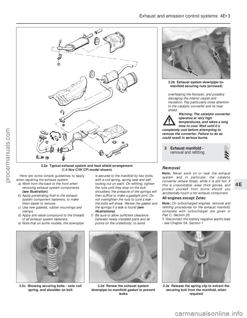
Here are some simple guidelines to apply
when repairing the exhaust system: a) Work from the back to the front when
removing exhaust system components
(see illustration) .
b) Apply penetrating fluid to the exhaust
system component fasteners, to make
them easier to remove.
c) Use new gaskets, rubber mountings and clamps.
d) Apply anti-seize compound to the threads
of all exhaust system fasteners
e) Note that on some models, the downpipe is secured to the manifold by two bolts,
with a coil spring, spring seat and self-
locking nut on each. On refitting, tighten
the nuts until they stop on the bolt
shoulders; the pressure of the springs will
then suffice to make a gastight joint. Do
not overtighten the nuts to cure a leak -
the bolts will shear. Renew the gasket and
the springs if a leak is found
(see
illustrations) .
f) Be sure to allow sufficient clearance between newly-installed parts and all
points on the underbody, to avoid overheating the floorpan, and possibly
damaging the interior carpet and
insulation. Pay particularly close attention
to the catalytic converter and its heat
shield.
Warning: The catalytic converter
operates at very high
temperatures, and takes a long
time to cool. Wait until it’s
completely cool before attempting to
remove the converter. Failure to do so
could result in serious burns.
3 Exhaust manifold - removal and refitting
3
Removal
Note: Never work on or near the exhaust
system and in particular, the catalytic
converter (where fitted), while it is still hot. If
this is unavoidable, wear thick gloves, and
protect yourself from burns should you
accidentally touch a hot exhaust component.
All engines except Zetec
Note: On turbocharged engines, removal and
refitting procedures for the exhaust manifold,
complete with turbocharger are given in
Part C, Section 20.
1 Disconnect the battery negative (earth) lead
- see Chapter 5A, Section 1.
Exhaust and emission control systems 4E•3
2.2b Exhaust system downpipe-to- manifold securing nuts (arrowed)
2.2a Typical exhaust system and heat shield arrangement (1.4 litre CVH CFi model shown)
2.2e Release the spring clip to extract thesecuring bolt from the manifold, when
required2.2d Renew the exhaust system
downpipe-to-manifold gasket to prevent
leaks2.2c Showing securing bolts - note coilspring, and shoulder on bolt
4E
1595Ford Fiesta Remakeprocarmanuals.com
http://vnx.su
Page 156 of 296
d)Refit the remaining parts in the reverse
order of removal. Tighten all fasteners to
the specified torque wrench settings
where given.
e) Where drained, refill the cooling system (see Chapter 1).
f) Run the engine, and check for exhaust
leaks. Check the coolant level when fully
warmed-up to normal operating
temperature.
4 Catalytic converter - general
information and precautions
The catalytic converter is a reliable and
simple device, which needs no maintenance
in itself, but there are some facts of which an
owner should be aware if the converter is to
function properly for its full service life. a) DO NOT use leaded petrol in a vehicle equipped with a catalytic converter - the
lead will coat the precious metals,
reducing their converting efficiency, and
will eventually destroy the converter.
b) Always keep the ignition and fuel systems
well-maintained in accordance with the
manufacturer’s schedule (see Chapter 1).
c) If the engine develops a misfire, do not drive the vehicle at all (or at least as little
as possible) until the fault is cured.
d) DO NOT push - or tow-start the vehicle -
this will soak the catalytic converter in
unburned fuel, causing it to overheat
when the engine does start.
e) DO NOT switch off the ignition at high engine speeds, ie do not “blip” the
throttle immediately before switching off.
f) DO NOT use fuel or engine oil additives - these may contain substances harmful to
the catalytic converter.
g) DO NOT continue to use the vehicle if the
engine burns oil to the extent of leaving a
visible trail of blue smoke.
h) Remember that the catalytic converter
operates at very high temperatures. DO
NOT, therefore, park the vehicle in dry
undergrowth, over long grass or piles of
dead leaves, after a long run.
I) Remember that the catalytic converter is FRAGILE. Do not strike it with tools
during servicing work.
j) In some cases, a sulphurous smell (like
that of rotten eggs) may be noticed from
the exhaust. This is common to many
catalytic converter-equipped vehicles.
Once the vehicle has covered a few
thousand miles, the problem should
disappear. Low quality fuel with a high
sulphur content will exacerbate this effect.
k) The catalytic converter used on a well-
maintained and well-driven vehicle should
last for between 50 000 and
100 000 miles. If the converter is no
longer effective, it must be renewed.
5 Positive crankcase ventilation system - checking
and component renewal
2
Checking
1 Checking procedures for the system
components are included in Chapter 1.
Component renewal - all
engines except Zetec
Air cleaner components
2 See Chapter 1.
Filter/oil separator and hoses
3All the components relating to the positive
crankcase ventilation system, with the
exception of the HCS engine filter/adapter
located on the underside of the air cleaner,
may be removed by simple disconnection and
withdrawal (having noted all connections for
subsequent refitting).
4 The refitting of all components is a reversal
of the removal procedure, ensuring that the
connections are correctly made.
Component renewal - Zetec
engines
Air cleaner components
5 See Chapter 1.
Positive Crankcase Ventilation (PCV)
valve
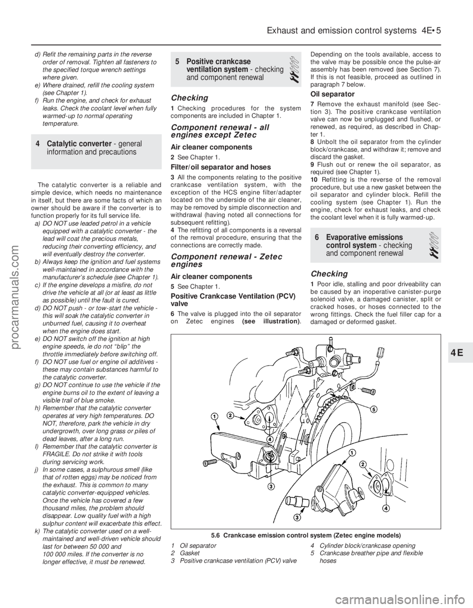
6The valve is plugged into the oil separator
on Zetec engines (see illustration).Depending on the tools available, access to
the valve may be possible once the pulse-air
assembly has been removed (see Section 7).
If this is not feasible, proceed as outlined in
paragraph 7 below.
Oil separator
7
Remove the exhaust manifold (see Sec-
tion 3). The positive crankcase ventilation
valve can now be unplugged and flushed, or
renewed, as required, as described in Chap-
ter 1.
8 Unbolt the oil separator from the cylinder
block/crankcase, and withdraw it; remove and
discard the gasket.
9 Flush out or renew the oil separator, as
required (see Chapter 1).
10 Refitting is the reverse of the removal
procedure, but use a new gasket between the
oil separator and cylinder block. Refill the
cooling system (see Chapter 1). Run the
engine, check for exhaust leaks, and check
the coolant level when it is fully warmed-up.
6 Evaporative emissions control system - checking
and component renewal
2
Checking
1 Poor idle, stalling and poor driveability can
be caused by an inoperative canister-purge
solenoid valve, a damaged canister, split or
cracked hoses, or hoses connected to the
wrong fittings. Check the fuel filler cap for a
damaged or deformed gasket.
Exhaust and emission control systems 4E•5
5.6 Crankcase emission control system (Zetec engine models)
1 Oil separator
2 Gasket
3 Positive crankcase ventilation (PCV) valve 4 Cylinder block/crankcase opening
5 Crankcase breather pipe and flexible
hoses
4E
1595Ford Fiesta Remakeprocarmanuals.com
http://vnx.su
Page 162 of 296
Ambient Ambient
temperature temperature
abovebelow
25°C (77°F) 25°C (77°F)
Fully-charged 1.210 to 1.230 1.270 to 1.290
70% charged 1.170 to 1.190 1.230 to 1.250
Fully-discharged 1.050 to 1.070 1.110 to 1.130
Note that the specific gravity readings
assume an electrolyte temperature of
15°C (60°F); for every 10°C (18°F) below 15°C
(60°F) subtract 0.007. For every 10°C (18°F)
above 15°C (60°F) add 0.007.
2 If the battery condition is suspect, first
check the specific gravity of electrolyte in
each cell. A variation of 0.040 or more
between any cells indicates loss of electrolyte
or deterioration of the internal plates.
3 If the specific gravity variation is 0.040 or
more, the battery should be renewed. If the
cell variation is satisfactory but the battery is
discharged, it should be charged as
described later in this Section.
Maintenance-free battery -
testing
4 In cases where a “sealed for life”
maintenance-free battery is fitted, topping-up
and testing of the electrolyte in each cell is not
possible. The condition of the battery can
therefore only be tested using a battery
condition indicator or a voltmeter.
5 If testing the battery using a voltmeter,
connect the voltmeter across the battery and
compare the result with those given in the
Specifications under “charge condition”. The
test is only accurate if the battery has not
been subjected to any kind of charge for the
previous six hours. If this is not the case,
switch on the headlights for 30 seconds, then
wait four to five minutes before testing the
battery after switching off the headlights. All
other electrical circuits must be switched off,
so check that the doors and tailgate are fully
shut when making the test.
6 If the voltage reading is less than 12.2 volts,
then the battery is discharged, whilst a
reading of 12.2 to 12.4 volts indicates a
partially discharged condition.
7 If the battery is to be charged, remove it
from the vehicle (Section 4) and charge it as
described later in this Section.
Standard and low maintenance
battery - charging
Note: The following is intended as a guide
only. Always refer to the manufacturer’s
recommendations (often printed on a label
attached to the battery) before charging a
battery.
8 Charge the battery at a rate of 3.5 to
4 amps and continue to charge the battery at
this rate until no further rise in specific gravity
is noted over a four hour period.
9 Alternatively, a trickle charger charging at
the rate of 1.5 amps can safely be used
overnight.
10 Specially rapid “boost” charges which are
claimed to restore the power of the battery in 1 to 2 hours are not recommended, as they
can cause serious damage to the battery
plates through overheating.
11
While charging the battery, note that the
temperature of the electrolyte should never
exceed 37.8°C (100°F).
Maintenance-free battery -
charging
Note: The following is intended as a guide
only. Always refer to the manufacturer’s
recommendations (often printed on a label
attached to the battery) before charging a
battery.
12 This battery type takes considerably
longer to fully recharge than the standard
type, the time taken being dependent on the
extent of discharge, but it can take anything
up to three days.
13 A constant voltage type charger is
required, to be set, when connected, to 13.9
to 14.9 volts with a charger current below
25 amps. Using this method, the battery
should be usable within three hours, giving a
voltage reading of 12.5 volts, but this is for a
partially discharged battery and, as
mentioned, full charging can take
considerably longer.
14 If the battery is to be charged from a fully
discharged state (condition reading less than
12.2 volts), have it recharged by your Ford
dealer or local automotive electrician, as the
charge rate is higher and constant supervision
during charging is necessary.
4 Battery -
removal and refitting
1
Note: Refer to the precautions in Section 1
before starting work.
Removal
1 The battery is located forward on the left-
hand side of the engine compartment, on a
platform welded to the vehicle structure.
2 Undo the retaining nut, then detach the
earth leads from the stud of the battery
negative (earth) terminal post. This is the
terminal to disconnect before working on, or
disconnecting, any electrical component on
the vehicle.
3 Pivot up the plastic cover from the positive
terminal, then unscrew the positive lead
retaining nut on the terminal. Detach the
positive lead from the terminal.
4 Release the clamp securing the battery to
its platform and remove it. Lift the battery
from its location, keeping it in an upright
position to avoid the possibility of corrosive
electrolyte spilling onto the paintwork.
5 Clean the battery terminal posts, clamps
and the battery casing. If the bulkhead is
rusted as a result of battery acid spilling onto
it, clean it thoroughly and re-paint with
reference to Chapter 1. 6
If you are renewing the battery, make sure
that you get one that’s identical, with the
same dimensions, amperage rating, cold
cranking rating, etc. Dispose of the old battery
in a responsible fashion. Most local authorities
have facilities for the collection and disposal
of such items - batteries contain sulphuric
acid and lead, and should not be simply
thrown out with the household rubbish!
Refitting
7 Refitting is a reversal of removal. Smear the
battery terminals with a petroleum-based jelly
prior to reconnecting. Always connect the
positive terminal clamp first and the negative
terminal clamp last.
5 Charging system - testing
2
Note:Refer to the precautions in Section 1
before starting work.
1 If the ignition warning light fails to
illuminate when the ignition is switched on,
first check the alternator wiring connections
for security. If satisfactory, check that the
warning light bulb has not blown, and that
the bulbholder is secure in its location in the
instrument panel. If the light still fails to
illuminate, check the continuity of the
warning light feed wire from the alternator to
the bulbholder. If all is satisfactory, the
alternator is at fault and should be renewed
or taken to an auto-electrician for testing and
repair.
2 If the ignition warning light illuminates when
the engine is running, stop the engine and
check that the drivebelt is correctly tensioned
(see Chapter 1) and that the alternator
connections are secure. If all is so far
satisfactory, have the alternator checked by
an auto-electrician for testing and repair.
3 If the alternator output is suspect even
though the warning light functions correctly,
the regulated voltage may be checked as
follows.
4 Connect a voltmeter across the battery
terminals and start the engine.
5 Increase the engine speed until the
voltmeter reading remains steady; the
reading should be approximately 13.5 to
14.6 volts.
6 Switch on as many electrical accessories
(eg, the headlights, heated rear window and
heater blower) as possible, and check that the
alternator maintains the regulated voltage at
around 13 to 14 volts.
7 If the regulated voltage is not as stated, the
fault may be due to worn brushes, weak brush
springs, a faulty voltage regulator, a faulty
diode, a severed phase winding or worn or
damaged slip rings. The alternator should be
renewed or taken to an auto-electrician for
testing and repair.
Starting and charging systems 5A•3
5A
1595Ford Fiesta Remakeprocarmanuals.com
http://vnx.su
Page 165 of 296
14Remove the rotor from the rear housing
and the stator. If difficulty is experienced, heat
the rear housing with a 200-watt soldering
iron for three or four minutes.
15 Unbolt the rectifier/brush box and stator
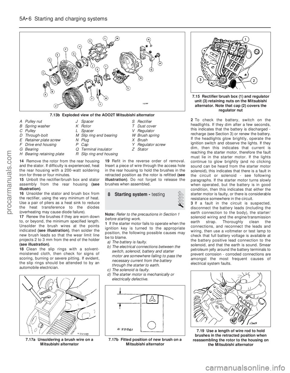
assembly from the rear housing (see
illustration) .
16 Unsolder the stator and brush box from
the rectifier, using the very minimum of heat.
Use a pair of pliers as a heat sink to reduce
the heat transference to the diodes
(overheating may cause diode failure).
17 Renew the brushes if they are worn down
to, or beyond, the minimum specified length.
Unsolder the brush wires at the points
indicated (see illustration) , then solder the
new brush leads so that the wear limit line
projects 2 to 3 mm from the end of the holder
(see illustration) .
18 Clean the slip rings with a solvent-
moistened cloth, then check for signs of
scoring, burning or severe pitting. If evident,
the slip rings should be attended to by an
automobile electrician. 19
Refit in the reverse order of removal.
Insert a piece of wire through the access hole
in the rear housing to hold the brushes in the
retracted position as the rotor is refitted (see
illustration) . Do not forget to release the
brushes when assembled.
8 Starting system - testing
1
Note:Refer to the precautions in Section 1
before starting work.
1 If the starter motor fails to operate when the
ignition key is turned to the appropriate
position, the following possible causes may
be to blame.
a) The battery is faulty.
b) The electrical connections between the
switch, solenoid, battery and starter
motor are somewhere failing to pass the
necessary current from the battery
through the starter to earth.
c) The solenoid is faulty.
d) The starter motor is mechanically or
electrically defective. 2
To check the battery, switch on the
headlights. If they dim after a few seconds,
this indicates that the battery is discharged -
recharge (see Section 3) or renew the battery.
If the headlights glow brightly, operate the
ignition switch and observe the lights. If they
dim, then this indicates that current is
reaching the starter motor, therefore the fault
must lie in the starter motor. If the lights
continue to glow brightly (and no clicking
sound can be heard from the starter motor
solenoid), this indicates that there is a fault in
the circuit or solenoid - see following
paragraphs. If the starter motor turns slowly
when operated, but the battery is in good
condition, then this indicates that either the
starter motor is faulty, or there is considerable
resistance somewhere in the circuit.
3 If a fault in the circuit is suspected,
disconnect the battery leads (including the
earth connection to the body), the starter/
solenoid wiring and the engine/transmission
earth strap. Thoroughly clean the
connections, and reconnect the leads and
wiring, then use a voltmeter or test lamp to
check that full battery voltage is available at
the battery positive lead connection to the
solenoid, and that the earth is sound. Smear
petroleum jelly around the battery terminals to
prevent corrosion - corroded connections are
amongst the most frequent causes of
electrical system faults.
5A•6 Starting and charging systems
7.19 Use a length of wire rod to hold
brushes in the retracted position when
reassembling the rotor to the housing on
the Mitsubishi alternator
7.17b Fitted position of new brush on a Mitsubishi alternator7.17a Unsoldering a brush wire on aMitsubishi alternator
7.15 Rectifier/brush box (1) and regulatorunit (3) retaining nuts on the Mitsubishialternator. Note that cap (2) covers the regulator nut
A Pulley nut
B Spring washer
C Pulley
D Through-bolt
E Retainer plate screw
F Drive end housing
G Bearing
H Bearing retaining plate J Spacer
K Rotor
L Spacer
M Slip ring end bearing
N Plug
P Cap
Q Terminal insulator
R Slip ring end housing S Rectifier
T Dust cover
V Regulator
W Brush spring
X Brush
Y Regulator screw
Z Stator
1595Ford Fiesta Remake
7.13b Exploded view of the AOO2T Mitsubishi alternatorprocarmanuals.com
http://vnx.su
Page 280 of 296
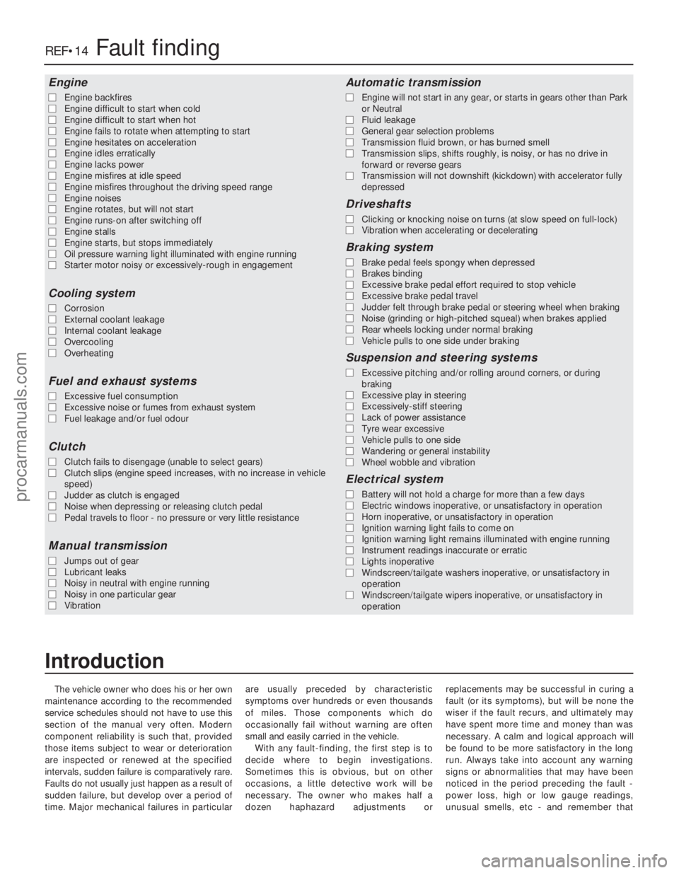
The vehicle owner who does his or her own
maintenance according to the recommended
service schedules should not have to use this
section of the manual very often. Modern
component reliability is such that, provided
those items subject to wear or deterioration
are inspected or renewed at the specified
intervals, sudden failure is comparatively rare.
Faults do not usually just happen as a result of
sudden failure, but develop over a period of
time. Major mechanical failures in particular are usually preceded by characteristic
symptoms over hundreds or even thousands
of miles. Those components which do
occasionally fail without warning are often
small and easily carried in the vehicle.
With any fault-finding, the first step is to
decide where to begin investigations.
Sometimes this is obvious, but on other
occasions, a little detective work will be
necessary. The owner who makes half a
dozen haphazard adjustments or replacements may be successful in curing a
fault (or its symptoms), but will be none the
wiser if the fault recurs, and ultimately may
have spent more time and money than was
necessary. A calm and logical approach will
be found to be more satisfactory in the long
run. Always take into account any warning
signs or abnormalities that may have been
noticed in the period preceding the fault -
power loss, high or low gauge readings,
unusual smells, etc - and remember that
Engine
m
m
Engine backfires
m
m Engine difficult to start when cold
m
m Engine difficult to start when hot
m
m Engine fails to rotate when attempting to start
m
m Engine hesitates on acceleration
m
m Engine idles erratically
m
m Engine lacks power
m
m Engine misfires at idle speed
m
m Engine misfires throughout the driving speed range
m
m Engine noises
m
m Engine rotates, but will not start
m
m Engine runs-on after switching off
m
m Engine stalls
m
m Engine starts, but stops immediately
m
m Oil pressure warning light illuminated with engine running
m
m Starter motor noisy or excessively-rough in engagement
Cooling system
m
mCorrosion
m
m External coolant leakage
m
m Internal coolant leakage
m
m Overcooling
m
m Overheating
Fuel and exhaust systems
m
mExcessive fuel consumption
m
m Excessive noise or fumes from exhaust system
m
m Fuel leakage and/or fuel odour
Clutch
m
mClutch fails to disengage (unable to select gears)
m
m Clutch slips (engine speed increases, with no increase in vehicle
speed)
m m Judder as clutch is engaged
m
m Noise when depressing or releasing clutch pedal
m
m Pedal travels to floor - no pressure or very little resistance
Manual transmission
m
mJumps out of gear
m
m Lubricant leaks
m
m Noisy in neutral with engine running
m
m Noisy in one particular gear
m
m Vibration
Automatic transmission
m
mEngine will not start in any gear, or starts in gears other than Park
or Neutral
m m Fluid leakage
m
m General gear selection problems
m
m Transmission fluid brown, or has burned smell
m
m Transmission slips, shifts roughly, is noisy, or has no drive in
forward or reverse gears
m m Transmission will not downshift (kickdown) with accelerator fully
depressed
Driveshafts
m mClicking or knocking noise on turns (at slow speed on full-lock)
m
m Vibration when accelerating or decelerating
Braking system
m
mBrake pedal feels spongy when depressed
m
m Brakes binding
m
m Excessive brake pedal effort required to stop vehicle
m
m Excessive brake pedal travel
m
m Judder felt through brake pedal or steering wheel when braking
m
m Noise (grinding or high-pitched squeal) when brakes applied
m
m Rear wheels locking under normal braking
m
m Vehicle pulls to one side under braking
Suspension and steering systems
m
mExcessive pitching and/or rolling around corners, or during
braking
m m Excessive play in steering
m
m Excessively-stiff steering
m
m Lack of power assistance
m
m Tyre wear excessive
m
m Vehicle pulls to one side
m
m Wandering or general instability
m
m Wheel wobble and vibration
Electrical system
m
mBattery will not hold a charge for more than a few days
m
m Electric windows inoperative, or unsatisfactory in operation
m
m Horn inoperative, or unsatisfactory in operation
m
m Ignition warning light fails to come on
m
m Ignition warning light remains illuminated with engine running
m
m Instrument readings inaccurate or erratic
m
m Lights inoperative
m
m Windscreen/tailgate washers inoperative, or unsatisfactory in
operation
m m Windscreen/tailgate wipers inoperative, or unsatisfactory in
operation
REF•14Fault finding
1595 Ford Fiesta Remake
Introduction
procarmanuals.com
http://vnx.su
Page 282 of 296
1595 Ford Fiesta Remake
REF•16Fault finding
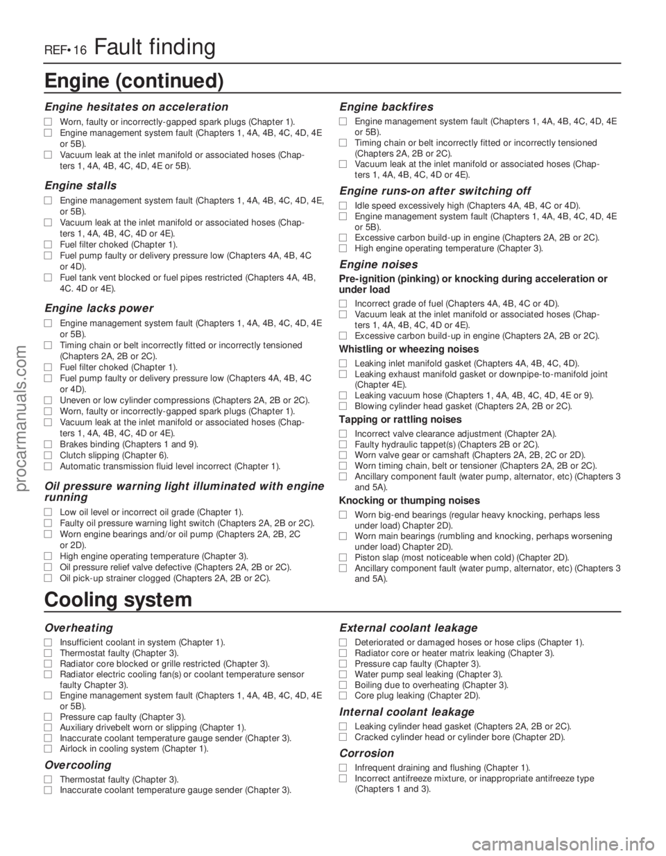
Cooling system
Overheating
m
mInsufficient coolant in system (Chapter 1).
m
m Thermostat faulty (Chapter 3).
m
m Radiator core blocked or grille restricted (Chapter 3).
m
m Radiator electric cooling fan(s) or coolant temperature sensor
faulty Chapter 3).
m m Engine management system fault (Chapters 1, 4A, 4B, 4C, 4D, 4E
or 5B).
m m Pressure cap faulty (Chapter 3).
m
m Auxiliary drivebelt worn or slipping (Chapter 1).
m
m Inaccurate coolant temperature gauge sender (Chapter 3).
m
m Airlock in cooling system (Chapter 1).
Overcooling
m
mThermostat faulty (Chapter 3).
m
m Inaccurate coolant temperature gauge sender (Chapter 3).
External coolant leakage
m
mDeteriorated or damaged hoses or hose clips (Chapter 1).
m
m Radiator core or heater matrix leaking (Chapter 3).
m
m Pressure cap faulty (Chapter 3).
m
m Water pump seal leaking (Chapter 3).
m
m Boiling due to overheating (Chapter 3).
m
m Core plug leaking (Chapter 2D).
Internal coolant leakage
m
mLeaking cylinder head gasket (Chapters 2A, 2B or 2C).
m
m Cracked cylinder head or cylinder bore (Chapter 2D).
Corrosion
m
mInfrequent draining and flushing (Chapter 1).
m
m Incorrect antifreeze mixture, or inappropriate antifreeze type
(Chapters 1 and 3).
Engine (continued)
Engine hesitates on acceleration
m
m Worn, faulty or incorrectly-gapped spark plugs (Chapter 1).
m
m Engine management system fault (Chapters 1, 4A, 4B, 4C, 4D, 4E
or 5B).
m m Vacuum leak at the inlet manifold or associated hoses (Chap-
ters 1, 4A, 4B, 4C, 4D, 4E or 5B).
Engine stalls
m mEngine management system fault (Chapters 1, 4A, 4B, 4C, 4D, 4E,
or 5B).
m m Vacuum leak at the inlet manifold or associated hoses (Chap-
ters 1, 4A, 4B, 4C, 4D or 4E).
m m Fuel filter choked (Chapter 1).
m
m Fuel pump faulty or delivery pressure low (Chapters 4A, 4B, 4C
or 4D).
m m Fuel tank vent blocked or fuel pipes restricted (Chapters 4A, 4B,
4C. 4D or 4E).
Engine lacks power
m mEngine management system fault (Chapters 1, 4A, 4B, 4C, 4D, 4E
or 5B).
m m Timing chain or belt incorrectly fitted or incorrectly tensioned
(Chapters 2A, 2B or 2C).
m m Fuel filter choked (Chapter 1).
m
m Fuel pump faulty or delivery pressure low (Chapters 4A, 4B, 4C
or 4D).
m m Uneven or low cylinder compressions (Chapters 2A, 2B or 2C).
m
m Worn, faulty or incorrectly-gapped spark plugs (Chapter 1).
m
m Vacuum leak at the inlet manifold or associated hoses (Chap-
ters 1, 4A, 4B, 4C, 4D or 4E).
m m Brakes binding (Chapters 1 and 9).
m
m Clutch slipping (Chapter 6).
m
m Automatic transmission fluid level incorrect (Chapter 1).
Oil pressure warning light illuminated with engine
running
m mLow oil level or incorrect oil grade (Chapter 1).
m
m Faulty oil pressure warning light switch (Chapters 2A, 2B or 2C).
m
m Worn engine bearings and/or oil pump (Chapters 2A, 2B, 2C
or 2D).
m m High engine operating temperature (Chapter 3).
m
m Oil pressure relief valve defective (Chapters 2A, 2B or 2C).
m
m Oil pick-up strainer clogged (Chapters 2A, 2B or 2C).
Engine backfires
m
mEngine management system fault (Chapters 1, 4A, 4B, 4C, 4D, 4E
or 5B).
m m Timing chain or belt incorrectly fitted or incorrectly tensioned
(Chapters 2A, 2B or 2C).
m m Vacuum leak at the inlet manifold or associated hoses (Chap-
ters 1, 4A, 4B, 4C, 4D or 4E).
Engine runs-on after switching off
m mIdle speed excessively high (Chapters 4A, 4B, 4C or 4D).
m
m Engine management system fault (Chapters 1, 4A, 4B, 4C, 4D, 4E
or 5B).
m m Excessive carbon build-up in engine (Chapters 2A, 2B or 2C).
m
m High engine operating temperature (Chapter 3).
Engine noises
Pre-ignition (pinking) or knocking during acceleration or
under load
m mIncorrect grade of fuel (Chapters 4A, 4B, 4C or 4D).
m
m Vacuum leak at the inlet manifold or associated hoses (Chap-
ters 1, 4A, 4B, 4C, 4D or 4E).
m m Excessive carbon build-up in engine (Chapters 2A, 2B or 2C).
Whistling or wheezing noises
m
mLeaking inlet manifold gasket (Chapters 4A, 4B, 4C, 4D).
m
m Leaking exhaust manifold gasket or downpipe-to-manifold joint
(Chapter 4E).
m m Leaking vacuum hose (Chapters 1, 4A, 4B, 4C, 4D, 4E or 9).
m
m Blowing cylinder head gasket (Chapters 2A, 2B or 2C).
Tapping or rattling noises
m
mIncorrect valve clearance adjustment (Chapter 2A).
m
m Faulty hydraulic tappet(s) (Chapters 2B or 2C).
m
m Worn valve gear or camshaft (Chapters 2A, 2B, 2C or 2D).
m
m Worn timing chain, belt or tensioner (Chapters 2A, 2B or 2C).
m
m Ancillary component fault (water pump, alternator, etc) (Chapters 3
and 5A).
Knocking or thumping noises
m mWorn big-end bearings (regular heavy knocking, perhaps less
under load) Chapter 2D).
m m Worn main bearings (rumbling and knocking, perhaps worsening
under load) Chapter 2D).
m m Piston slap (most noticeable when cold) (Chapter 2D).
m
m Ancillary component fault (water pump, alternator, etc) (Chapters 3
and 5A).
procarmanuals.com
http://vnx.su
Page 294 of 296
Fault finding - clutch - REF•17
Fault finding - cooling system - REF•16
Fault finding - driveshafts - REF•19
Fault finding - electrical system - 5A•2,
12 •3, REF •20
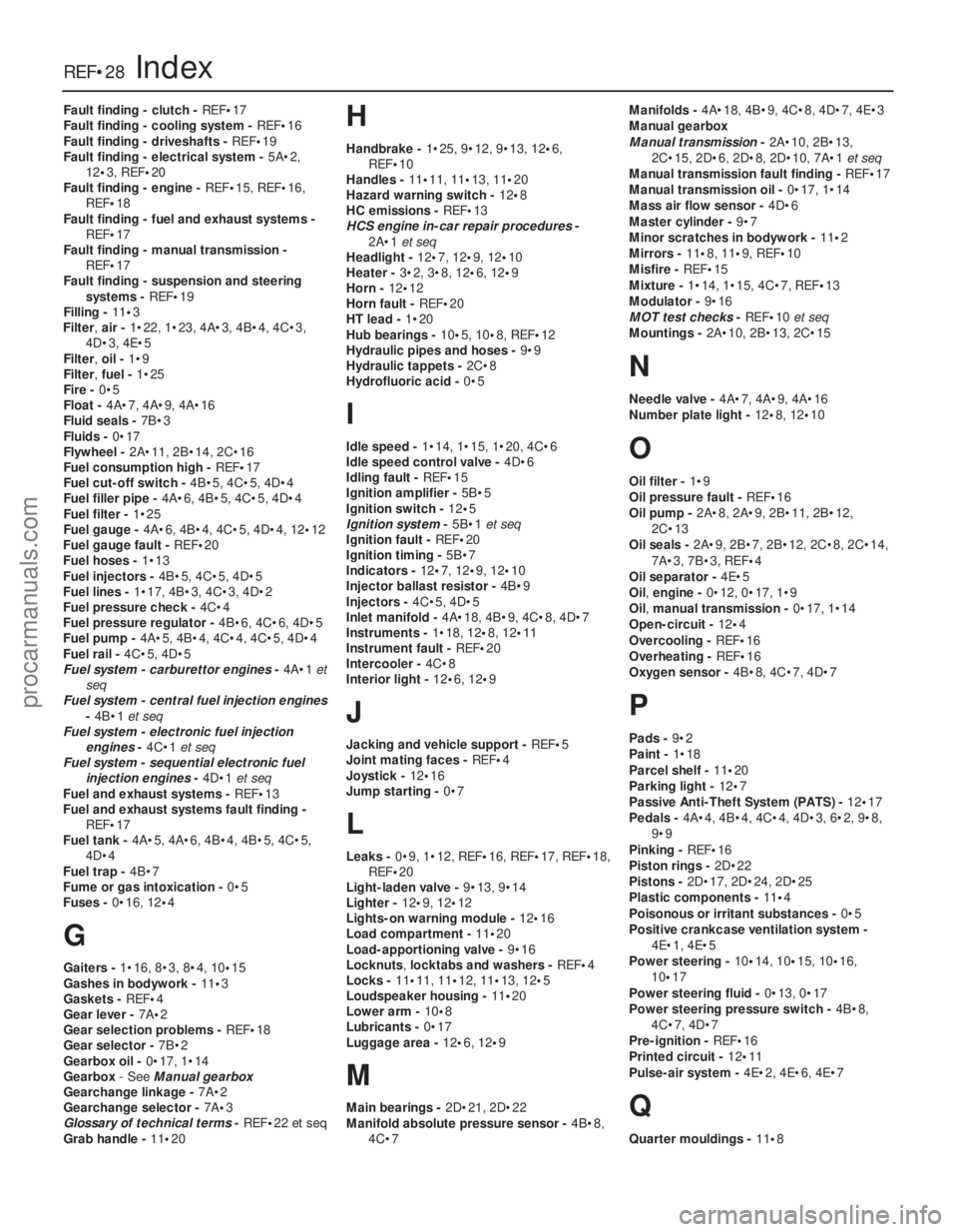
Fault finding - engine - REF•15, REF•16,
REF•18
Fault finding - fuel and exhaust systems -
REF•17
Fault finding - manual transmission - REF•17
Fault finding - suspension and steering
systems - REF•19
Filling - 11•3
Filter, air -1•22, 1•23, 4A•3, 4B•4, 4C•3,
4D•3, 4E•5
Filter, oil -1•9
Filter, fuel -1•25
Fire - 0•5
Float - 4A•7, 4A•9, 4A•16
Fluid seals - 7B•3
Fluids - 0•17
Flywheel - 2A•11, 2B•14, 2C•16
Fuel consumption high - REF•17
Fuel cut-off switch - 4B•5, 4C•5, 4D•4
Fuel filler pipe - 4A•6, 4B•5, 4C•5, 4D•4
Fuel filter - 1•25
Fuel gauge - 4A•6, 4B•4, 4C•5, 4D•4, 12 •12
Fuel gauge fault - REF•20
Fuel hoses - 1•13
Fuel injectors - 4B•5, 4C•5, 4D•5
Fuel lines - 1•17, 4B•3, 4C•3, 4D•2
Fuel pressure check - 4C•4
Fuel pressure regulator - 4B•6, 4C•6, 4D•5
Fuel pump - 4A•5, 4B•4, 4C•4, 4C•5, 4D•4
Fuel rail - 4C•5, 4D•5
Fuel system - carburettor engines -4A•1 et
seq
Fuel system - central fuel injection engines
-4B•1 et seq
Fuel system - electronic fuel injection engines -4C•1 et seq
Fuel system - sequential electronic fuel
injection engines -4D•1 et seq
Fuel and exhaust systems - REF•13
Fuel and exhaust systems fault finding - REF•17
Fuel tank - 4A•5, 4A•6, 4B•4, 4B•5, 4C•5,
4D•4
Fuel trap - 4B•7
Fume or gas intoxication - 0•5
Fuses - 0•16, 12 •4
G
Gaiters - 1•16, 8•3, 8•4, 10 •15
Gashes in bodywork - 11•3
Gaskets - REF •4
Gear lever - 7A•2
Gear selection problems - REF•18
Gear selector - 7B•2
Gearbox oil - 0•17, 1•14
Gearbox - See Manual gearbox
Gearchange linkage - 7A•2
Gearchange selector - 7A•3
Glossary of technical terms - REF•22 et seq
Grab handle - 11•20
H
Handbrake - 1•25, 9•12, 9•13, 12 •6,
REF•10
Handles - 11•11, 11•13, 11 •20
Hazard warning switch - 12•8
HC emissions - REF•13
HCS engine in-car repair procedures -
2A•1 et seq
Headlight - 12•7, 12 •9, 12 •10
Heater - 3•2, 3•8, 12 •6, 12•9
Horn - 12•12
Horn fault - REF•20
HT lead - 1•20
Hub bearings - 10•5, 10•8, REF •12
Hydraulic pipes and hoses - 9•9
Hydraulic tappets - 2C•8
Hydrofluoric acid - 0•5
I
Idle speed -1•14, 1•15, 1•20, 4C•6
Idle speed control valve - 4D•6
Idling fault - REF•15
Ignition amplifier - 5B•5
Ignition switch - 12•5
Ignition system -5B•1 et seq
Ignition fault - REF•20
Ignition timing - 5B•7
Indicators - 12•7, 12•9, 12 •10
Injector ballast resistor - 4B•9
Injectors - 4C•5, 4D•5
Inlet manifold - 4A•18, 4B•9, 4C•8, 4D•7
Instruments - 1•18, 12•8, 12•11
Instrument fault - REF•20
Intercooler - 4C•8
Interior light - 12•6, 12 •9
J
Jacking and vehicle support - REF•5
Joint mating faces - REF•4
Joystick - 12•16
Jump starting - 0•7
L
Leaks -0•9, 1•12, REF •16, REF•17, REF•18,
REF•20
Light-laden valve - 9•13, 9•14
Lighter - 12•9, 12 •12
Lights-on warning module - 12•16
Load compartment - 11•20
Load-apportioning valve - 9•16
Locknuts ,locktabs and washers - REF•4
Locks - 11•11, 11•12, 11•13, 12 •5
Loudspeaker housing - 11•20
Lower arm - 10•8
Lubricants - 0•17
Luggage area - 12•6, 12•9
M
Main bearings - 2D•21, 2D•22
Manifold absolute pressure sensor - 4B•8,
4C•7 Manifolds -
4A•18, 4B•9, 4C•8, 4D•7, 4E•3
Manual gearbox
Manual transmission -2A•10, 2B•13,
2C•15, 2D•6, 2D•8, 2D•10, 7A•1 et seq
Manual transmission fault finding - REF•17
Manual transmission oil - 0•17, 1•14
Mass air flow sensor - 4D•6
Master cylinder - 9•7
Minor scratches in bodywork - 11•2
Mirrors - 11 •8, 11•9, REF •10
Misfire - REF•15
Mixture - 1•14, 1•15, 4C•7, REF•13
Modulator - 9•16
MOT test checks - REF•10et seq
Mountings - 2A•10, 2B•13, 2C•15
N
Needle valve - 4A•7, 4A•9, 4A•16
Number plate light - 12•8, 12 •10
O
Oil filter - 1•9
Oil pressure fault - REF•16
Oil pump - 2A•8, 2A•9, 2B•11, 2B•12,
2C•13
Oil seals - 2A•9, 2B•7, 2B•12, 2C•8, 2C•14,
7A•3, 7B•3, REF •4
Oil separator - 4E•5
Oil, engine - 0•12, 0•17, 1•9
Oil, manual transmission - 0•17, 1•14
Open-circuit - 12•4
Overcooling - REF•16
Overheating - REF•16
Oxygen sensor - 4B•8, 4C•7, 4D•7
P
Pads -9•2
Paint - 1•18
Parcel shelf - 11•20
Parking light - 12•7
Passive Anti-Theft System (PATS) - 12•17
Pedals - 4A•4, 4B•4, 4C•4, 4D•3, 6•2, 9•8,
9•9
Pinking - REF•16
Piston rings - 2D•22
Pistons - 2D•17, 2D•24, 2D•25
Plastic components - 11•4
Poisonous or irritant substances - 0•5
Positive crankcase ventilation system - 4E•1, 4E•5
Power steering - 10•14, 10•15, 10•16,
10 •17
Power steering fluid - 0•13, 0•17
Power steering pressure switch - 4B•8,
4C•7, 4D•7
Pre-ignition - REF•16
Printed circuit - 12•11
Pulse-air system - 4E•2, 4E•6, 4E•7
Q
Quarter mouldings - 11•8
REF•28Index
1595 Ford Fiesta Remakeprocarmanuals.com
http://vnx.su