1988 PONTIAC FIERO tire size
[x] Cancel search: tire sizePage 376 of 1825
2.8 LITER V-6 6A2-25
Fitting
1. Select rings comparable in size to the piston being
used.
2. Slip
the compression ring in the cylinder bore;
then press the ring down into the cylinder bore
about 6mm above ring travel. Be sure ring is
square with cylinder wall.
3. Measure the space or gap between the ends of the
ring with a feeler gage (Figure
6A2-33).
4. If
the gap between the ends of the ring is below
specifications, remove the ring and try another
for fit.
5. Fit each compression ring to the cylinder in
which it is going to be used.
6. If the pistons have not been cleaned and inspected
as previously outlined, do so.
7. Slip the outer surface of the top and second
compression ring into the respective piston ring
groove and roll the ring entirely around the
groove (Figure
6A2-34). If binding occurs at any
point, the cause should be determined. If there is
a ring groove, remove by dressing with a fine cut
file. If the binding is caused by a distorted ring,
check a new ring.
Installation
1. Install oil ring spacer in groove being sure ends
are butted and not overlapped.
2. Hold
spacer ends butted and install lower steel oil
ring rail.
3. Install upper
steel oil ring rail with gap staggered.
4. Flex
the oil ring assembly to make sure ring is
free. If binding occurs, the cause should be
detemined. If caused by ring groove, remove by
dressing groove with a fine cut file. If binding is
caused by a distorted ring, check a new ring.
5. Install second compression ring. Stagger gap
from other rings.
6. Install top compression ring with gap properly
located.
ENGINE ASSEMBLY
Removal
Disconnect battery.
Remove air cleaner.
Remove hood. Drain radiator.
Remove lower radiator hose.
Remove upper fan shroud.
Remove upper radiator hose and coolant
recovery hose.
Remove transmission cooler lines. Remove radiator.
Remove fan assembly.
Remove heater hoses.
Disconnect carburetor linkage, includes cruise
control detent cable.
Remove vacuum brake booster line.
Remove distributor cap and lay wiring aside.
Disconnect necessary wires and hoses.
Remove power steering pump and lay aside. Raise
vehicle.
Remove exhaust pipes at exhaust manifold.
Remove dust cover.
Remove converter bolts.
Disconnect starter wires.
Remove bell housing bolts.
Remove motor mount through bolts.
Disconnect fuel lines at fuel pump.
Lower vehicle. Support transmission.
Remove
A.I.R./Converter pipes bracket.
Remove engine, include removing wire from
bracket at rear left of engine.
Installation
Position engine assembly in vehicle.
Attach motor mount to engine brackets and
lower engine in place.
Remove engine lifting device.
Remove transmission floor jack.
Raise vehicle on hoist.
Install mount "through" bolts. Torque to
specifications.
Install bell housing bolts. Torque to
specifications.
On vehicles with automatic transmission, install
converter to flywheel attaching bolts. Torque to
specifications.
Install flywheel splash shield of conveter housing
cover as applicable. Torque attaching bolts to
specifications.
Install starter wires.
Connect fuel lines.
Connect exhaust pipe at manifold.
Lower vehicle on hoist.
Reinstall power steering pump, if so equipped.
Connect necessary wires and hoses.
Install radiator and fan shroud and reconnect
radiator and heater hoses.
Fill cooling system.
Fill crankcase with oil. See owner's manual for
specifications.
Install air cleaner.
Install hood.
Connect battery cables.
NOTICE: To avoid possible arcing of battery,
connect positive battery cable first.
22. Start engine, check for leaks and check timing.
CRANKSHAFT
The crankshaft can be removed while the engine
is dissasembled for overhaul, as previously outlined or
without complete disassembly.
Removal
1. With the engine removed from the vehicle,
remove the clutch assembly (if equipped) and
flywheel. Mount engine in stand and clamp
securely.
Page 398 of 1825
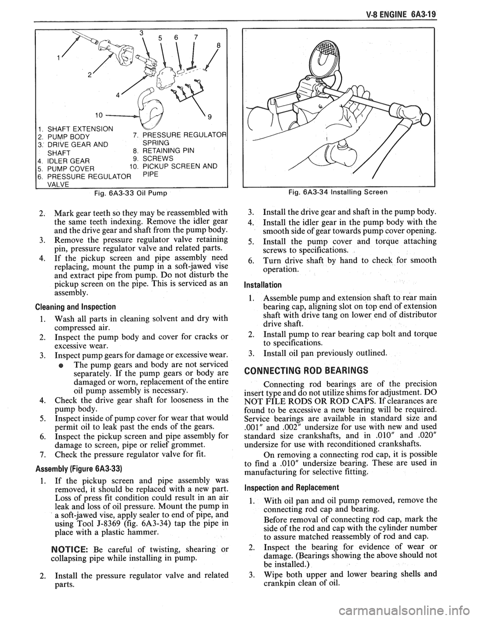
V-8 ENGINE 6A3-19
1 SHAFT EXTENSION
2 PUMP BODY
3 DRIVE GEAR AND
4 IDLER GEAR
9 SCREWS
5 PUMP COVER 10 PICKUP SCREEN AND
6 PRESSURE REGULATOR
Fig.
6A3-33 Oil Pump
2. Mark
gear teeth so they may be reassembled with
the same teeth indexing. Remove the idler gear
and the drive gear and shaft from the pump body.
3. Remove
the pressure regulator valve retaining
pin, pressure regulator valve and related parts.
4. If the pickup screen and pipe assembly need
replacing, mount the pump in a soft-jawed vise
and extract pipe from pump. Do not disturb the
pickup screen on the pipe. This is serviced as an
assembly.
Cleaning and lnspection
1. Wash all parts in cleaning solvent and dry with
compressed air.
2. Inspect the pump body and cover for cracks or
excessive wear.
3. Inspect
pump gears for damage or excessive wear.
The pump gears and body are not serviced
separately. If the pump gears or body are
damaged or worn, replacement of the entire
oil pump assembly is necessary.
4. Check the drive gear shaft for looseness in the
pump body.
5. Inspect inside of pump cover for wear that would
permit oil to leak past the ends of the gears.
6. Inspect the pickup screen and pipe assembly for
damage to screen, pipe or relief grommet.
7. Check the pressure regulator valve for fit.
Assembly (Figure 6A3-33)
1. If
the pickup screen and pipe assembly was
removed, it should be replaced with a new part.
Loss of press fit condition could result in an air
leak and loss of oil pressure. Mount the pump in
a soft-jawed vise, apply sealer to end of pipe, and
using Tool J-8369 (fig. 6A3-34) tap the pipe in
place with a plastic hammer.
NOTICE: Be careful of twisting, shearing or
collapsing pipe while installing in pump.
2. Install the
pressure regulator valve and related
parts.
Fig. 6A3-34 Installing Screen
3. Install the drive gear and shaft in the pump body.
4. Install
the idler gear in the pump body with the
smooth side of gear towards pump cover opening.
5. Install the pump cover and torque attaching
screws to specifications.
6. Turn
drive shaft by hand to check for smooth
operation.
Installation
1. Assemble
pump and extension shaft to rear main
bearing cap, aligning slot on top end of extension
shaft with drive tang on lower end of distributor
drive shaft.
2. Install
pump to rear bearing cap bolt and torque
to specifications.
3. Install
oil pan previously outlined.
CONNECTING ROD BEARINGS
Connecting rod bearings are of the precision
insert type and do not utilize shims for adjustment. DO
NOT FILE RODS OR ROD CAPS. If clearances are
found to be excessive a new bearing will be required.
Service bearings are available in standard size and
.001" and ,002" undersize for use with new and used
standard size crankshafts, and in
.010" and .020"
undersize for use with reconditioned crankshafts.
On removing a connecting rod cap, it is possible
to find a
.010" undersize bearing. These are used in
manufacturing for selective fitting.
lnspection and Replacement
1. With
oil pan and oil pump removed, remove the
connecting rod cap and bearing.
Before removal of connecting rod cap, mark the
side of the rod and cap with the cylinder number
to assure matched reassembly of rod and cap.
2. Inspect
the bearing for evidence of wear or
damage. (Bearings showing the above should not
be installed.)
3. Wipe both upper and lower bearing shells and
crankpin clean of oil.
Page 404 of 1825
V-8 ENGINE 6A3-25
Assembly
1. Lubricate piston pin holes in piston and
connecting rod to facilitate installation of pin.
2. Place connecting rod in piston and hold in place
with piston pin guide and piston pin. Place
assembly on fixture and support assembly.
3. Using piston pin installer, 5-24086-9, press the
piston pin into the piston and connecting rod (Fig.
6A3-46).
NOTICE: After installer hub bottoms on support
assembly, do not exceed
5000 psi pressure, as this
could cause structural damage to the tool.
4. Remove piston
and connecting rod assembly
from tool and check piston for freedom of
movement on piston pin.
Piston Rings
All compression rings are marked on the upper
side of the ring. When installing compression rings,
make sure the MARKED SIDE IS TOWARD THE
TOP
OF THE PISTON. The top ring is chrome faced,
or treated with molybdenum for maximum life. The
second compression ring is a tapered face acting as
both a compression and oil control ring.
The oil control rings are of three piece type,
consisting of two segments (rails) and a spacer.
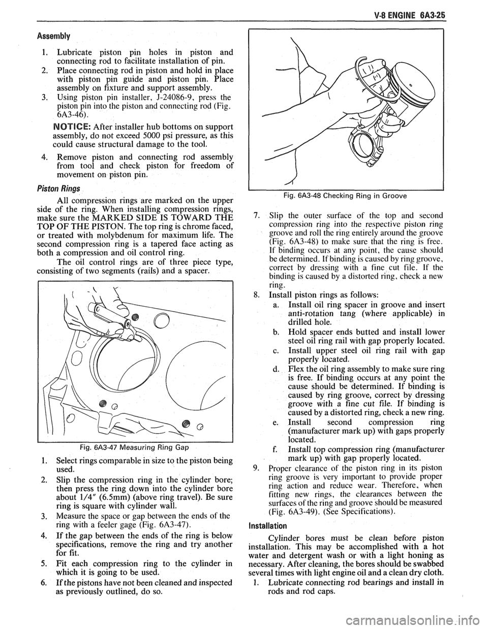
Fig. 6A3-47 Measuring Ring Gap
1. Select rings comparable in size to the piston being
used.
2. Slip the compression ring in the cylinder bore;
then press the ring down into the cylinder bore
about
1/4" (6.5mm) (above ring travel). Be sure
ring is square with cylinder wall.
3. Measure the space or gap between the ends of the
ring with a feeler gage (Fig.
6A3-47).
4. If the gap between the ends of the ring is below
specifications, remove the ring and try another
for fit.
5. Fit each compression ring to the cylinder in
which it is going to be used.
6. If the pistons have not been cleaned and inspected
as previously outlined, do so.
Fig. 6A3-48 Checking Ring in Groove
7. Slip the outer surface of the top and second
compression ring into the respective piston ring
groove and roll the ring entirely around the groove
(Fig.
6A3-48) to make sure that the ring is free.
If binding occurs at any point, the cause should
be determined. If binding is caused by ring groove,
correct by dressing with a fine cut file. If
the
binding is caused by a distorted ring, check a new
ring.
8. Install piston rings as follows:
a. Install oil ring spacer in groove and insert
anti-rotation tang (where applicable) in
drilled hole.
b. Hold spacer ends butted and install lower
steel oil ring rail with gap properly located.
c. Install
upper steel oil ring rail with gap
properly located.
d. Flex the oil ring assembly to make sure ring
is free. If binding occurs at any point the
cause should be determined. If binding is
caused by ring groove, correct by dressing
groove with a fine cut file. If binding is
caused by a distorted ring, check a new ring.
e. Install second compression ring
(manufacturer mark up) with gaps properly
located.
f. Install top compression ring (manufacturer
mark up) with gap properly located.
9. Proper clearance of the piston ring in its piston
ring groove is very important to provide proper
ring action and reduce wear. Therefore, when
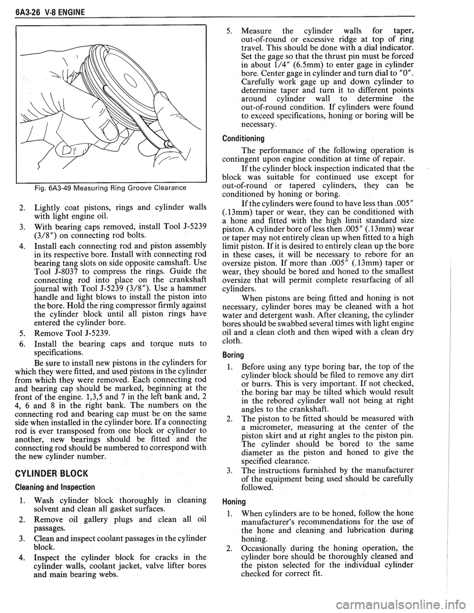
fitting new rings, the clearances between the
surfaces of the ring and groove should be measured
(Fig.
6A3-49). (See Specifications).
Installation
Cylinder bores must be clean before piston
installation. This may be accomplished with a hot
water and detergent wash or with a light honing as
necessary. After cleaning, the bores should be swabbed
several times with light engine oil and a clean dry cloth.
1. Lubricate connecting rod bearings and install in
rods and rod caps.
Page 405 of 1825
6A3-26 V-8 ENGINE
Fig. 6A3-49 Measuring Ring Groove Clearance
2. Lightly coat pistons, rings
and cylinder walls
with light engine oil.
3. With bearing caps removed, install Tool J-5239
(3/8") on connecting rod bolts.
4. Install
each connecting rod and piston assembly
in its respective bore. Install with connecting rod
bearing tang slots on side opposite camshaft. Use
Tool
5-8037 to compress the rings. Guide the
connecting rod into place on the crankshaft
journal with Tool
5-5239 (3/8"). Use a hammer
handle and light blows to install the piston into
the bore. Hold the ring compressor firmly against
the cylinder block until all piston rings have
entered the cylinder bore.
5. Remove Tool J-5239.
6. Install the bearing caps and torque nuts to
specifications.
Be sure to install new pistons in the cylinders for
which they were fitted, and used pistons in the cylinder
from which they were removed. Each connecting rod
and bearing cap should be marked, beginning at the
front of the engine.
1,3,5 and 7 in the left bank and, 2
4, 6 and 8 in the right bank. The numbers on the
connecting rod and bearing cap must be on the same
side when installed in the cylinder bore. If a connecting
rod is ever transposed from one block or cylinder to
another, new bearings should be fitted and the
connecting rod should be numbered to correspond with
the new cylinder number.
CYLINDER BLOCK
Cleaning and Inspection
1. Wash cylinder block thoroughly in cleaning
solvent and clean all gasket surfaces.
2. Remove oil gallery plugs and clean all oil
passages.
3. Clean and inspect coolant passages in the cylinder
block.
4. Inspect the cylinder block for cracks in the
cylinder walls, coolant jacket, valve lifter bores
and main bearing webs. 5.
Measure the cylinder walls for taper,
out-of-round or excessive ridge at top of ring
travel. This should be done with a dial indicator.
Set the gage so that the thrust pin must be forced
in about
1/4" (6.5mm) to enter gage in cylinder
bore. Center gage in cylinder and turn dial to
"0".
Carefully work gage up and down cylinder to
determine taper and turn it to different points
around cylinder wall to determine the
out-of-round condition. If cylinders were found
to exceed specifications, honing or boring will be
necessary.
Conditioning
The performance of the following operation is
contingent upon engine condition at time of repair.
If the cylinder block inspection indicated that the
block was suitable for continued use except for
out-of-round or tapered cylinders, they can be
conditioned by honing or boring.
If the cylinders were found to have less than
.005"
(.13mm) taper or wear, they can be conditioned with
a hone and fitted with the high limit standard size
piston. A cylinder bore of less then
.005" (. 13mm) wear
or taper may not entirely clean up when fitted to a high
limit piston. If it is desired to entirely clean up the bore
in these cases, it will be necessary to
rebore for an
oversize piston. If more than
.005" (. 13mm) taper or
wear, they should be bored and honed to the smallest
oversize that will permit complete resurfacing of all
cylinders.
When pistons are being fitted and honing is not
necessary, cylinder bores may be cleaned with a hot
water and detergent wash. After cleaning, the cylinder
bores should be swabbed several times with light engine
oil and a clean cloth and then wiped with a clean dry
cloth.
Boring
1. Before using any type boring bar, the top of the
cylinder block should be filed to remove any dirt
or burrs. This is very important. If not checked,
the boring bar may be tilted which would result
in the
rebored cylinder wall not being at right
angles to the crankshaft.
2. The
piston to be fitted should be measured with
a micrometer, measuring at the center of the
piston skirt and at right angles to the piston pin.
The cylinder should be bored to the same
diameter as the piston and honed to give the
specified clearance.
3.
The instructions furnished by the manufacturer
of the equipment being used should be carefully
followed.
Honing
1. When cylinders are to be honed, follow the hone
manufacturer's recommendations for the use of
the hone and cleaning and lubrication during
honing.
2. Occasionally during the honing operation, the
cylinder bore should be thoroughly cleaned and
the piston selected for the individual cylinder
checked for correct fit.
Page 1118 of 1825
AUTOMATIC TRANSMISSION 7A-3
PRELIMARY CHECKING PROCEDURE
The condition of an automatic transmission not
operating properly may be influenced by one, or a
combination of the following items:
e Fluid level high/low
(Refer to Section 7A1)
e Engine performance
(Refer to Sections 6 and 6E)
T.V. cable adjustment
(Refer to Section
7A1)
e Manual linkage adjustment
(Refer to Section
7A1)
e Internal fluid leaks
(Refer to Transmission Unit Repair section)
e Electrical system
(Refer to Section 6E and 8A)
e Transmission or other mechanical component
(Refer to Transmission Unit Repair section)
e Vacuum modulator
(Refer to appropriate Hydraulic Diagnosis
Section)
NOISE AND VIBRATION ANALYSIS
A noise or vibration that is noticeable when the
vehicle is in motion, MAY NOT be the result of the
transmission.
If noise or vibration is noticeable in "Park"
(P)
and "Neutral" (N) with engine at idle, but is less
noticeable as
RPM's increase, the cause may be from
poor engine performance.
e Tires for
- Uneven wear
- Imbalance
- Mixed sizes
- Mixed radial and bias ply
(Refer to Section 3E)
e Suspension components for
- Alignment and wear
- Loose fasteners
(Refer to Section 3C)
e Engine/Transmission mounts for
- Damage
- Loose bolts
(Refer
to Sections 6A and 7A2)
e Transmission case mounting holes for:
- Missing bolts, nuts, studs
- Stripped threads
- Cracks
e Flywheel for:
- Missing or loose bolts
- Cracks
- Imbalance
(Refer to Section 6A)
e Torque converter for: - Missing or loose bolts or lugs - Missing or loose balance weights
- Imbalance
TRANSMISSION FLUID LEVEL INFORMATION
Checking fluid level, color and condition at
regular intervals will provide early diagnosis
information about the transmission. This information
may then be used to correct a condition that, if not
detected early, could result in major transmission
repairs.
When adding or changing fluid, use only
DEXRONO 11, or equivalent. Refer to Section OB of
this Service Manual for maintenance information and
servicing intervals.
Fluid level should be checked when it reaches
normal operating temperatures of
190-200°F.
(88-93°C). This temperature is reached after
approximately 15 miles (24 km) of highway
driving.
e Fluid color - Should be dark red (may be dark green)
NOTICE: Do not overfill. Overfilling will cause
foaming, loss of fluid and possible damage to the
transmission.
Inaccurate fluid level readings will result if
checked immediately after the vehicle has been
operated:
- In high abmient temperatures above 90°F
(32°C)
- At sustained high speeds
- In heavy city traffic during hot weather
- As a towing vehicle - In commercial service (taxi or police use)
TRANSMISSION FLUID CHECKING
PROCEDURE
(Refer to Figure 3)
1. Park vehicle on level ground.
2. Apply parking
brake and block wheels.
3. Start
engine and operate vehicle for 15 minutes or
until a normal operating temperature is reached.
4. Move gear
selector through all gear positions.
5. Move
gear selector to "Park" (P).
6. Check fluid level, color and condition.
Page 1178 of 1825
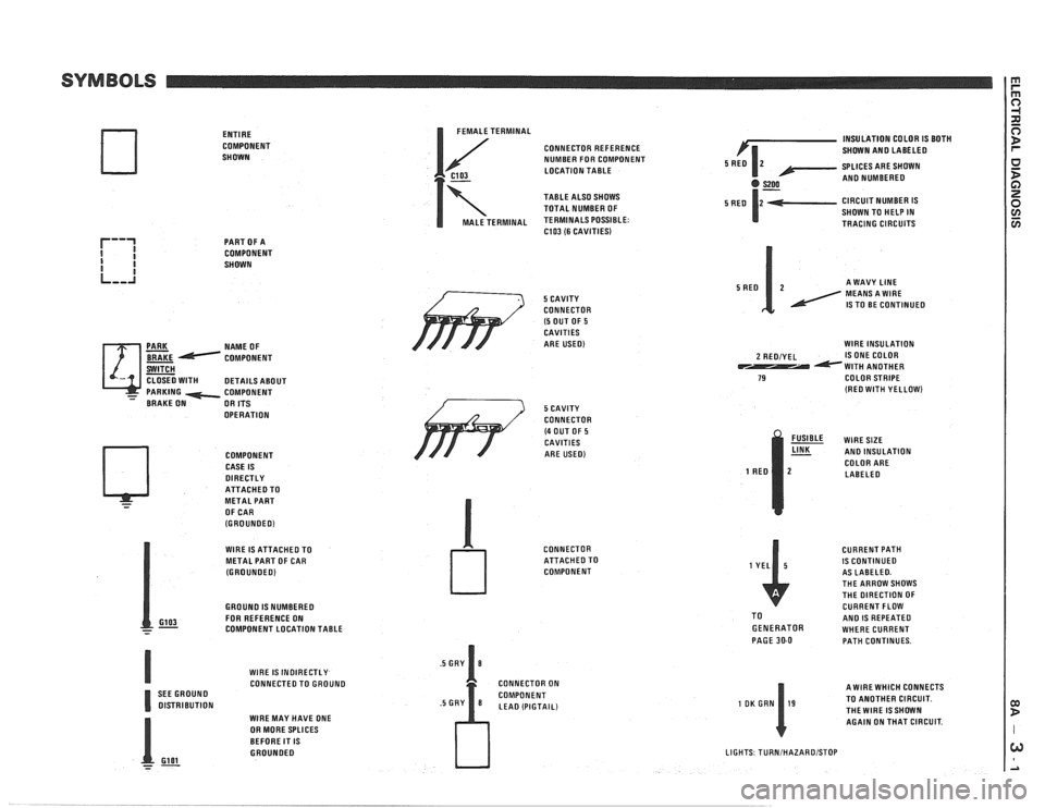
ENTIRE
COMPONENT
SHOWN
PART OF A
COMPONENT
SHOWN
NAME OF
COMPONENT
OPERATION COMPONENT
CASE IS
DIRECTLY ATTACHEOTO
- METAL PART
OF CAR
(GROUNOEO)
I FEMALE TERMINAL
CONNECTOR REFERENCE
NUMBER FOR COMPONENT
C103 LOCATION TABLE
7
TABLE ALSO SHOWS
TOTAL NUMBER OF
MALE TERMINAL TERMINALS POSSIBLE: C103 (6 CAVITIES)
/' 5 CAVITY
CONNECTOR
(5 OUT OF 5 CAVITIES
ARE USED)
WlRE IS ATTACHED TO
METAL PART OF CAR
(GROUNOEO)
GROUNO
IS NUMBEREO
GI03 FOR REFERENCE ON - - - COMPONENT LOCATION TABLE
WlRE
IS INOIRECTLY CONNECTED TO GROUNO
SEE GROUNO
OlSTRlBUTlON WlRE MAY HAVE ONE
OR MORE SPLICES
BEFORE IT
IS GROUNOEO
- Gl 01 --
/ 3 5 CAVITY
CONNECTOR
(4 OUT OF 5 CAVITIES
ARE USED)
CONNECTOR
ATTACHEOTO
COMPONENT
CONNECTOR ON
COMPONENT
LEA0 (PIGTAIL) INSULATION
COLOR
IS BOTH
SHOWN AN0 LABELEO
SPLICES ARE SHOWN
AN0 NUMBEREO
CIRCUIT NUMBER
IS SHOWN TO HELP IN
TRACING CIRCUITS
A WAVY
LINE MEANS A WlRE IS TO BE CONTINUED
WlRE INSULATION
2 REOIYEL IS ONE COLOR WlTH ANOTHER 79 COLOR STRIPE (RE0 WlTH YELLOW)
% WIRESIZE AN0 INSULATION
COLOR ARE
LABELEO
CURRENT PATH
IS CONTINUED
AS LABELEO.
THE ARROW SHOWS
THE DIRECTION OF
CURRENT FLOW
TO
AN0 IS REPEATED GENERATOR WHERE CURRENT
PAGE 30-0 PATH CONTINUES.
A WlRE WHICH CONNECTS
TO ANOTHER CIRCUIT.
THEWIRE ISSHOWN AGAIN ON THAT CIRCUIT.
LIGHTS TURNIHAZAROISTOP