1988 PONTIAC FIERO flat tire
[x] Cancel search: flat tirePage 271 of 1825
484-18 REAR AXLE
4. With transmission in park and both wheels and
tires clear of ground, (wheels will r~tate in opp-
osite directions), measure torque required to
rotateaxle shafts with a torque
wrenchattached
to J 2619-1. If the torque reading is less than
48 N.m (35 1b.ft.) the unit should be disassembled
and repaired as required.
5. Reinstall wheel and tire assembly.
Disassemble
Limited Slip Differential.
1. Remove ring gear bolts.
NOTICE: Left hand threaded ring gear bolts.
2. Tap
ring gear off differential housing with soft
face hammer.
NOTICE: Mark differential case halves with
alignment mark before disassembly because they
could be assembled
180" off from original position.
3. Remove 8 screws holding differential housing
halves together and separate halves. 4.
Remove pinion shaft, 4 differential pinions,
thrust washers side gears, side gear shims
(if
required), spring plates, and compression springs
from housing. Discard compression springs. New
springs are required for assembly.
5. Mark each cone during disassembly to ensure
that the same brake cone will be assembled with
the same case as originally assembled. If shims
are used they must be marked so that they will be
assembled in original case half.
6. If differential bearings are damaged remove with
tool J-22888-D. (Fig. 15).
Inspect
Disassemble
The inspection procedures for the positraction
differential are the same as those for the standard
rear axle except for the side gear positioning
shims. The side gear positioning shims are used
to control case size.
1. The shims should be free of cracks, nicks, or
burrs.
2. Assemble brake cones in case and measure to
determine correct shim size. Measure the
distance from case mating surface to flat surface
on brake cone when fully seated. Select shim size
from chart below.
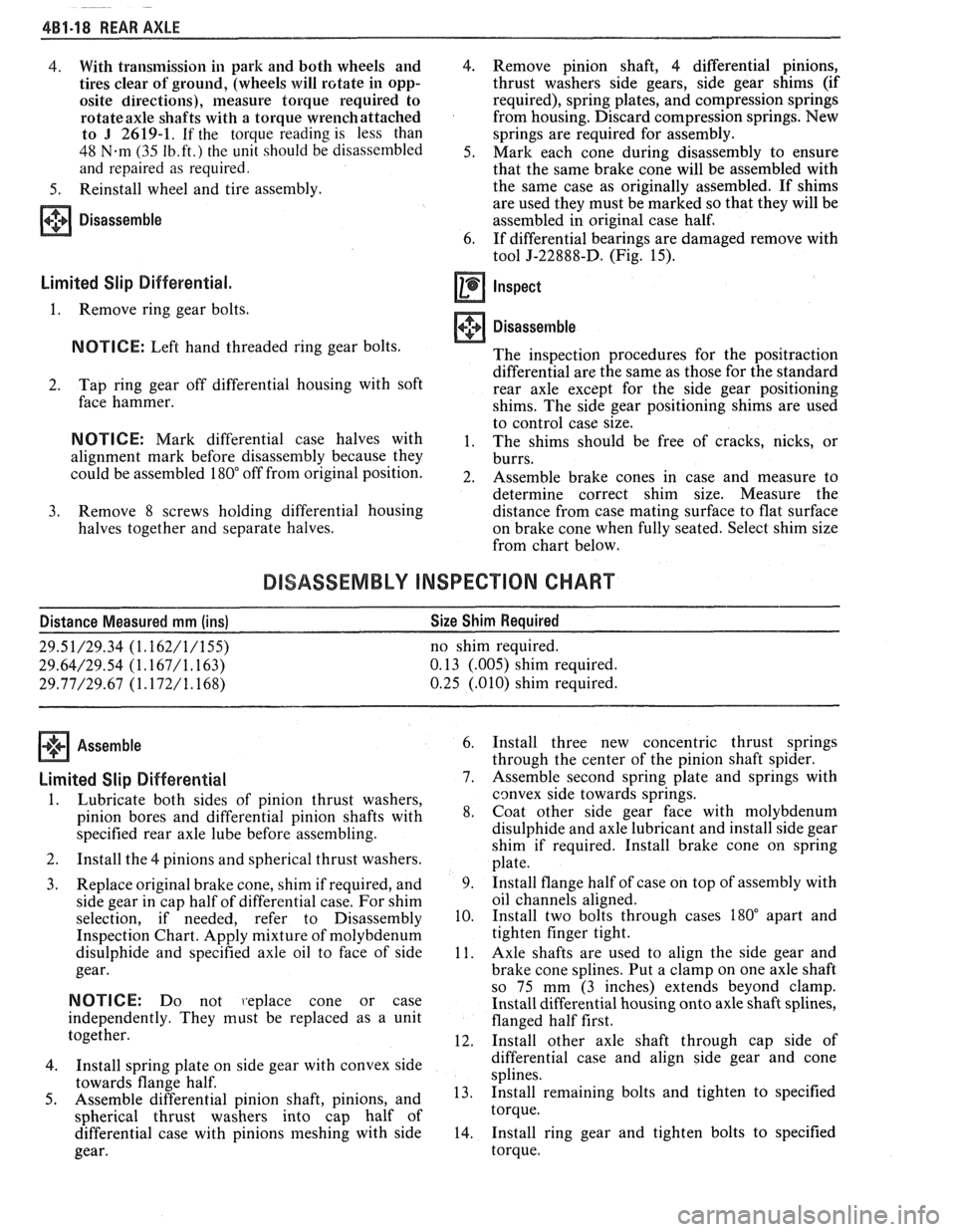
DISASSEMBLY INSPECTION CHART
Distance Measured mm (ins) Size
Shim Required
29.51/29.34 (1.162/1/155) no shim required.
29.64/29.54 (1.167/1.163) 0.13 (.005) shim required.
29.77D9.67 (1.172/1.168) 0.25 (.010) shim required.
Assemble
Limited Slip Differential
1.
Lubricate both sides of pinion thrust washers,
pinion bores and differential pinion shafts with
specified rear axle lube before assembling.
2. Install the 4 pinions and spherical thrust washers.
3. Replace original brake cone, shim if required, and
side gear in cap half of differential case. For shim
selection, if needed, refer to Disassembly
Inspection Chart. Apply mixture of molybdenum
disulphide and specified axle oil to face of side
gear.
NOTICE: Do not 1.eplace cone or case
independently. They must be replaced as a unit
together.
4. Install spring
plate on side gear with convex side
towards flange half.
5. Assemble differential pinion shaft, pinions, and
spherical thrust washers into cap half of
differential case with pinions meshing with side
gear. 6.
Install three new concentric thrust springs
through the center of the pinion shaft spider.
7. Assemble second spring plate and springs with
cgnvex side towards springs.
8. Coat other side gear face with molybdenum
disulphide and axle lubricant and install side gear
shim if required. Install brake cone on spring
plate.
9. Install
flange half of case on top of assembly with
oil channels aligned.
10. Install
two bolts through cases
180" apart and
tighten finger tight.
11. Axle shafts are used to align the side gear and
brake cone splines. Put a clamp on one axle shaft
so 75 mm (3 inches) extends beyond clamp.
Install differential housing onto axle shaft splines,
flanged half first.
12. Install other axle shaft through cap side of
differential case and align side gear and cone
splines.
13. Install remaining
bolts and tighten to specified
torque.
14. Install
ring gear and tighten bolts to specified
torque.
Page 276 of 1825
REAR AXLE 4B-3
Noise which originates in other places cannot be
corrected by adjustment or replacement of parts in the
differential. It should also be remembered that rear
axle gears, like any other mechanical device, are not
absolutely quiet and should be accepted as being
commercially quiet unless some abnormal noise is
present.
To make a systematic check for axle noise under
standard conditions, observe the following:
1. Select a level smooth asphalt road to reduce tire
noise and body drumming.
2. Check rear axle lubricant to assure correct level,
then drive car far enough to thoroughly warm up
rear axle lubricant.
3. Note speed and RPM at which noise occurs. Then
stop car and with automatic transmission in neutral,
run engine slowly up and down through engine speeds, corresponding to car speed at which noise
was most pronounced, to determine if it is caused by
exhaust, muffler roar or other engine conditions.
4. Tire noise changes with different road surfaces,
but rear axle noise does not. Temporarily
inflating all tires to approximately 50 pounds
pressure for
test purposes only will materially
alter noise caused by tires, but will not affect noise
caused by rear axle. Rear axle noise usually stops
when coasting at speeds under 30 miles per hour;
however, tire noise continues, but with lower
tone, as car speed is reduced. Rear axle noise
usually changes when comparing acceleration
and coast, but tire noise remains about the same.
Distinguish between tire noise and rear axle noise
by noting if noise varies with various speeds or
sudden acceleration and deceleration; exhaust
and axle noise show variations under these
conditions while tire noise remains constant and
is more pronounced at speeds of 20 to 30 miles
per hour. Further check for tire noise by driving
car over smooth pavements or dirt roads (not
gravel) with tires at normal pressure. If noise is
caused by tires, it will noticeably change or
disappear and reappear with changes in road
surface.
5. Loose or rough front wheel bearings will cause
noise which may be confused with rear axle
noises; however, front wheel bearing noise does
not change when comparing drive and coast.
Light application of brakes while holding car
speed steady will often cause wheel bearing noise
to diminish, as this takes some weight off the
bearing. Front wheel bearings may be easily
checked for noise by jacking up the wheels and
spinning them, also by shaking wheels to
determine if bearings are loose.
6. Rear suspension rubber bushings and spring
insulators dampen out rear axle noise when
correctly installed. Check to see that no metallic
contact exists between the spring and spring
opening in frame or between upper and lower
control arm bushings and frame or axle housing
brackets.
Metal-to-metal contact at those points
may result in telegraphing road noise and normal axle
noise which would not be objectionable if
dampened by bushings.
AXLE NOISES
Gear Noise
After the noise has been determined as being in
the
axle by following the above appraisal procedure,
the type of axle noise should be determined to aid in
maki~~g repairs if necessary.
Gear noise (whine) is audible from 20 to
55 mph
under four driving conditions:
1. Drive - Acceleration or heavy pull.
2. Road Load - Car driving load or constant speed.
3. Float
- Using
enough throttle to keep the car from
driving the engine
- car slows down gradually but
engine still pulls slightly.
4. Coast
- Throttle closed and car in gear. Gear
noise most frequently has periods where noise is
more prominent, usually 30 to 40 mph and 50 to
55 mph.
Bearing Noise
Bad bearings generally produce more of a rough
growl or grating sound, rather than the whine typical
of gear noise. Bearing noise frequently "wow-wows" at
bearing rpm, indicating a defective pinion or rear axle
case side bearing. This noise could easily be confused
with rear wheel bearing noise. Inspect and replace as
required.
Rear Wheel Bearing Noise
A rough rear wheel bearing produces a noise
which continues with car coasting at low speed and
transmission in neutral. Noise may diminish some by
gentle braking. With rear wheels jacked up, spin rear
wheels by hand while listening at hubs for evidence of
rough (noisy) wheel bearing.
I(noclc At Low Speeds
Low speed knock can be caused by worn
universal joints or a side gear hub counterbore in a case
that has worn oversize. Inspect and replace universal
joint or case and side gear as required.
Baclclash Clunk
Excessive clunk with acceleration and
deceleration is caused by worn differential pinion shaft,
excessive clearance between axle shaft and side gear
splines, excessive clearance between side gear hub and
counterbore in case worn pinion and side gear teeth,
worn thrust washers and excessive drive pinion and
rear gear backlash. Remove worn parts and replace as
required, selecting close fitting parts when possible.
Adjust pinion and ring gear backlash.
REAR AXLE STANDARD AND LIMITED-SLIP
1. Noise is the same in "Drive" or "Coast".
a. Road noise.
b. Tire noise.
c. Front wheel bearing noise.
Page 284 of 1825
REAR AXLE 48-1 1
Rear Wheel Bolt
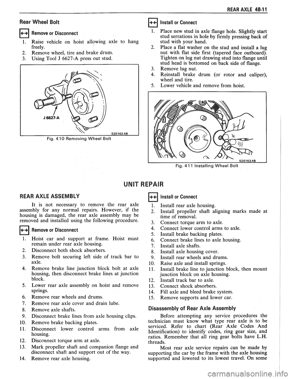
Remove or Disconnect 1.
1. Raise vehicle on hoist allowing axle to hang
freely. 2.
2. Remove
wheel, tire and brake drum.
3. Using Tool J 6627-A press out stud.
Fig. 4 10 Removing Wheel Bolt
REAR AXLE ASSEMBLY
Install or Connect
Fig. 4 11 Installing Wheel Bolt
UNIT REPAIR
Remove or Disconnect
Place new stud in axle flange hole. Slightly start
stud serrations in hole by firmly pressing back of
stud with your hand.
Place a flat washer on the stud and install a lug
nut with flat side first (tapered face outboard).
Tighten on lug nut drawing stud into flange until
stud head is bottomed on back side of flange.
Remove lug nut.
Reinstall brake drum (or rotor and caliper),
wheel and tire.
Lower vehicle and remove from hoist.
It is not necessary to remove the rear axle
assembly for any normal repairs. However, if the
housing is damaged, the rear axle assembly may be
removed and installed using the following procedure.
Hoist car and support at frame. Hoist must
remain under rear axle housing.
Disconnect both shock absorbers.
Remove bolt securing left side of track bar to
axle.
Remove brake line junction block bolt at axle
housing, then disconnect brake lines at junction
block.
Lower rear axle assembly on hoist and remove
springs.
Remove rear wheels and drums.
Remove rear axle cover and drain lube.
Remove axle shafts.
Disconnect brake lines from axle housing clips.
Remove brake backing plates.
Disconnect lower control arms from axle
housing.
Disconnect torque arm at axle.
Mark propeller shaft and companion flange and
disconnect shaft and support out of the way.
Remove rear axle housing.
Install or Connect
Install rear axle housing.
Install propeller shaft aligning marks made at
time of removal.
Connect torque arm to axle.
Connect lower control arms to axle.
Install brake backing plates.
Connect brake lines to axle housing.
Install axle shafts.
Install axle housing cover.
Install rear wheels and drums.
Raise axle and install springs.
Install brake line to junction block, then mount
junction block on axle housing.
Install track bar to axle.
Connect shock absorbers.
Fill axle and bleed brake system.
Remove supports and lower car.
Disassembly of Rear Axle Assembly
Before attempting any service procedures the
technician must know what type rear axle is to be
serviced. Refer to chart (Rear Axle Codes And
Identification) to identify codes, ring gear size, and
ratios. Remember that all ring gear bolts have L.H.
threads.
Most rear axle service repairs can be made by
supporting the car by the frame with the axle housing
supported and lowered to its lowest travel. On some
Page 296 of 1825
BRAKES 5-3
DIAGNOSIS AND INSPECTION
BRAKE SYSTEM TESTING
(Figures
2 through 4)
Brakes should be tested on dry, clean, reasonably
smooth and level roadway. A true test of brake performance
cannot be made if the roadway is wet, greasy or covered
with loose dirt so that all tires do not grip the road equally.
Testing will also be affected if the roadway is crowned
which would throw the weight of the car toward the wheels
on one side. If the roadway is too rough, the wheels will tend
to bounce. Test brakes at different car speeds with both light and
heavy pedal pressure, avoid locking the brakes and sliding
the tires. Locked brakes and sliding tires do not indicate
brake efficiency, because heavily braked, but turning
wheels will stop the car in less distance than locked brakes.
More tire-to-road friction is present with a heavily braked
turning tire than with a sliding tire. The brake system is designed and balanced to avoid
locking the wheels, except at very high deceleration levels.
The shortest stopping distance and best control is achieved
without brake lock-up.
Because of high deceleration capability, a firmer pedal
may be felt at higher deceleration levels.
External Conditions That Affect Brake Performance
1. Tires. Tires having unequal contact and grip on road
will cause unequal braking. Tires must be equally
inflated and tread pattern of right and left tires must
be approximately equal.
2. Car Loading. A heavily loaded car requires more
braking effort. When a car has unequal loading, the
most heavily loaded wheels require more braking
power than others.
3. Wheel Alignment. Misalignment of the wheels, par-
ticularly excessive camber and caster, will cause the
brakes to pull to one side.
4. Front Wheel Bearings. A loose front wheel bearing
BRAKE FLUID LEAKS
With engine running at idle and the transmission in neu-
tral, depress the brake pedal and hold a constant foot pres-
sure.
If the pedal gradually falls away with the constant
pressure, the hydraulic system may be leaking. Perform a
visual check to confirm any suspected leak.
Check the master cylinder fluid levels. While a slight drop
in reservoir level does result from normal lining wear, an
abnormally low level in either reservoir indicates
a leak in
the system. The hydraulic system may be leaking either
internally or externally. See "Master Cylinder Check."
Also, the system may appear to pass this test but still have
slight leakage.
If fluid levels are normal, check the vacuum booster
pushrod length. If an incorrect length pushrod is found,
adjust or replace the
pushrod. Check the service brake
pedal travel and the parking brake adjustment.
When checking the fluid levels, the master cylinder reser-
voir may be as low as
25 mm (1 inch) from the top if the front
linings are worn. This is not abnormal.
MASTER CYLINDER CHECK
These checks will help locate some master cylinder mal-
functions. Use the Brake Diagnosis Charts to help isolate
the problem if it is not found by using these tests.
1. Check for a cracked master cylinder casting or brake
fluid around the master cylinder. Leaks are indicated
only if there is at least a drop of fluid. A damp condi-
tion is not abnormal.
2. Check for a binding pedal linkage.
3. Disassemble the master cylinder and check for swol-
len or stretched piston
seal(s). If swollen seals are
found, substandard or contaminated brake fluid
should be suspected.
If contaminated, all compo-
nents should be disassembled and cleaned. All rub-
ber components should be replaced and all the pipes
should be flushed.
permits the front wheel to tilt and lose contact with the
SUBSTANDARD OR CONTAMINATED brake shoe linings causing erratic brake operation. BRAKE FLUID
WARNING LAMP OPERATION
The brake system uses a single red "BRAKE" warning
lamp located in the instrument panel cluster. When the
ignition switch is in the "START" position, the "BRAKE"
warning lamp should come on. It should go off when the
ignition switch returns to the "RUN" position.
The following conditions will activate the "BRAKE"
warning lamp:
1. Parking brake applied. The lamp should be on when
tfie parking brake is applied and the ignition switch is
"ON."
2. Pressure differential switch detects a failure. See
"Brake Pressure Differential Warning Switch" in this
section. Improper
brake fluid, mineral oil or water in the fluid may
cause the brake fluid to boil or the rubber components to
deteriorate.
If piston cups are swollen, the rubber parts have dete-
riorated. This deterioration may also be seen by swollen
wheel cylinder piston cups on the drum brake wheels or a
swollen master cylinder cover diaphragm.
If rubber deterioration is evident, disassemble all hydrau-
lic parts and wash with alcohol. Dry these parts with com-
pressed air before assembly to keep alcohol out of the
system. Replace all rubber parts in the system, including
hoses. Check for fluid on the linings. If excessive fluid is
found, replace the linings.
If master cylinder piston seals are satisfactory, check for
leakage or excessive heat conditions. If condition is not
found, drain fluid, flush with brake fluid, fill and bleed the
system.
Page 308 of 1825
BRAKES 5-15
lnspect rear drum brake shoe and lining assemblies.
Install or Connect (Figures 12 and 13)
When the thickness of any lining is worn within 0.76 mm
Raise vehicle. See Section OA. (0.030-inch)
of the shoe or rivet, the shoe and lining
1. Cable at brake shoe operating lever. assemblies must
be replaced. Replace shoe and lining
Bend retainer fingers. assemblies
in axle sets.
2. Brake drum and wheel.
3. Rear cable at connector.
0 Lower vehicle. See Section oA. INSPECTING AND REFINISHING ROTORS
Adjust
0 Parking brake. See Section 5C3.
Parking Brake Rear Cable (Disc Brakes)
Remove or Disconnect (Figures
12 and 13)
0 Raise vehicle. See Section OA.
1. Rear cable from connector.
0 Loosen adjusting nut at equalizer.
2. Cable from brake caliper.
Push forward on caliper parking brake apply
lever.
@ Remove cable from tang in lever.
Release lever.
Lower vehicle. See Section OA.
Install or Connect (Figures 12 and
13)
Raise vehicle. See Section OA.
1. Cable to brake caliper.
0 Push forward on caliper parking brake apply
lever.
0 Install cable in lever tang.
Release lever.
2. Rear cable to connector. 0 Lower vehicle. See Section OA.
0 Parking brake. See Section 586.
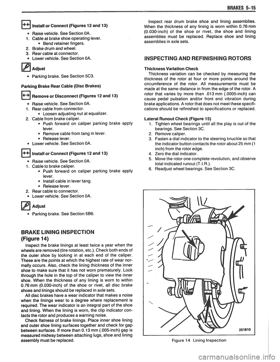
BRAKE LINING INSPECTION
(Figure 14)
lnspect the brake linings at least twice a year when the
wheels are removed (tire rotation, etc.). Check both ends of
the outer shoe by looking in at each end of the caliper.
These are the points at which the highest rate of wear nor-
mally occurs. Also, check the lining thickness of the inner
shoe to make sure that it has not worn prematurely. Look
through the hole in the top of the caliper to view the inner
shoe. When the thickness of any lining is worn to within
0.76
mm (0.030-inch) of the shoe or rivet, all disc brake
shoes and linings should be replaced in axle sets.
All disc brakes have a wear indicator that makes a noise
when the linings wear to a degree where replacement is
required. The wear indicator is an integral part of the shoe
and lining. When the lining is worn, the clip indicator con-
tacts the rotor and produces a warning noise.
Check flatness of brake linings. Place inner shoe lining
and outer shoe lining surfaces together and check for gap
between surfaces. If more than 0.13 mm
(.OO&inch) gap is
measured midway between attaching lugs, shoe and lining
assembly must be replaced. Thickness
Variation Check
Thickness variation can be checked by measuring the
thickness of the rotor at four or more points around the
circumference of the rotor. All measu'rements must be
made at the same distance in from the edge of the rotor. A
rotor that varies by more than
.013 mm (.0005-inch) can
cause pedal pulsation
and/or front end vibration during
brake applications. A rotor that does not meet these specifi-
cations should be refinished to specifications or replaced.
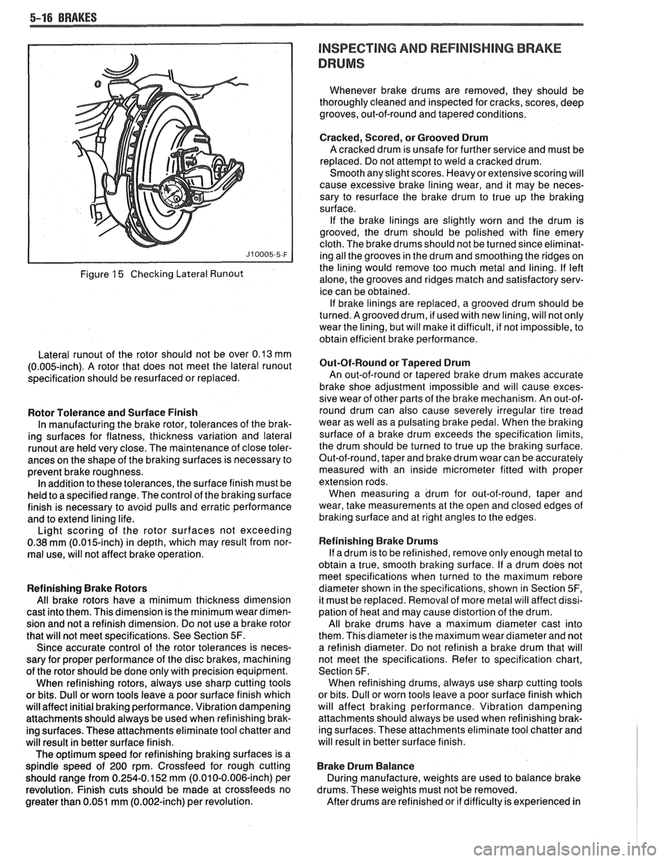
Lateral
Wunout Check (Figure 15)
1. Tighten wheel bearings until all the play is out of the
bearings. See Section 3C.
2. Remove caliper.
3. Fasten a dial indicator to the steering knuckle so that
the indicator button contacts the rotor about
25 mm (1
inch) from the rotor edge.
4. Zero the dial indicator.
5. Move the rotor one complete revolution, and observe
total indicated
runout (T.I.R.).
6. Readjust wheel bearings. See Section 3C.
Figure 14 Lining Inspection
Page 309 of 1825
5-16 BRAKES
Figure 15 Checking Lateral Runout
Lateral runout of the rotor should not be over 0.13 mm
(0.005-inch). A rotor that does not meet the lateral runout
specification should be resurfaced or replaced.
Rotor Tolerance and Surface Finish
In manufacturing the brake rotor, tolerances of the brak-
ing surfaces for flatness, thickness variation and lateral
runout are held very close. The maintenance of close toler-
ances on the shape of the braking surfaces is necessary to
prevent brake roughness. In addition to these tolerances, the surface finish must be
held to a specified range. The control of the braking surface
finish is necessary to avoid pulls and erratic performance
and to extend lining life.
Light scoring of the rotor surfaces not exceeding
0.38
mrn (0.015-inch) in depth, which may result from nor-
mal use, will not affect brake operation.
Refinishing Brake Rotors
All brake rotors have a minimum thickness dimension
cast into them. This dimension is the minimum wear dimen-
sion and not a refinish dimension. Do not use a brake rotor
that will not meet specifications. See Section
5F.
Since accurate control of the rotor tolerances is neces-
sary for proper performance of the disc brakes, machining
of the rotor should be done only with precision equipment.
When refinishing rotors, always use sharp cutting tools
or bits. Dull or worn tools leave a poor surface finish which
will affect initial braking performance. Vibration dampening
attachments should always be used when refinishing brak-
ing surfaces. These attachments eliminate tool chatter and
will result in better surface finish.
The optimum speed for refinishing braking surfaces is a
spindle speed of 200 rpm. Crossfeed for rough cutting
should range from 0.254-0.152 mm (0.010-0.006-inch) per
revolution. Finish cuts should be made at crossfeeds no
greater than 0.051 mm (0.002-inch) per revolution.
INSPECTING AND REFlNlSHlMG BRAKE
DRUMS
Whenever brake drums are removed, they should be
thoroughly cleaned and inspected for cracks, scores, deep
grooves, out-of-round and tapered conditions.
Cracked, Scored, or Grooved Drum
A cracked drum is unsafe for further service and must be
replaced. Do not attempt to weld a cracked drum.
Smooth any slight scores. Heavy or extensive scoring will
cause excessive brake lining wear, and it may be neces-
sary to resurface the brake drum to true up the braking
surface.
If the brake linings are slightly worn and the drum is
grooved, the drum should be polished with fine emery
cloth. The brake drums should not be turned since eliminat-
ing all the grooves in the drum and smoothing the ridges on
the lining would remove too much metal and lining. If left
alone, the grooves and ridges match and satisfactory serv-
ice can be obtained. If brake linings are replaced, a grooved drum should be
turned. Agrooved drum, if used with new lining, will not only
wear the lining, but will make it difficult, if not impossible, to
obtain efficient brake performance.
But-Of-Round or Tapered Drum
An out-of-round or tapered brake drum makes accurate
brake shoe adjustment impossible and will cause exces-
sive wear of other parts of the brake mechanism. An out-of-
round drum can also cause severely irregular tire tread
wear as well as a pulsating brake pedal. When the braking
surface of a brake drum exceeds the specification limits,
the drum should be turned to true up the braking surface.
Out-of-round, taper and brake drum wear can be accurately
measured with an inside micrometer fitted with proper
extension rods. When measuring a drum for out-of-round, taper and
wear, take measurements at the open and closed edges of
braking surface and at right angles to the edges.
Refinishing Brake Drums
If adrum is to be refinished, remove only enough metal to
obtain a true, smooth braking surface. If a drum does not
meet specifications when turned to the maximum
rebore
diameter shown in the specifications, shown in Section 5F,
it must be replaced. Removal of more metal will affect dissi-
pation of heat and may cause distortion of the drum.
All brake drums have a maximum diameter cast into
them. This diameter is the maximum wear diameter and not
a refinish diameter. Do not refinish a brake drum that will
not meet the specifications. Refer to specification chart,
Section 5F. When refinishing drums, always use sharp cutting tools
or bits. Dull or worn tools leave a poor surface finish which
will affect braking performance. Vibration dampening
attachments should always be used when refinishing brak-
ing surfaces. These attachments eliminate tool chatter and
will result in better surface finish.
Brake Drum Balance
During manufacture, weights are used to balance brake
drums. These weights must not be removed.
After drums are refinished or if difficulty is experienced in
Page 325 of 1825

e Remove lug nuts securing rotor to hub.
e Lower car.
o Torque lug nuts. See WHEELS AND
TIRES.
SHOE AND LINING ASSEMBLIES
Figures 5 thru 8
Remove or Disconnect
1. Caliper as previously described.
2 Outboard shoe and lining (27) (Figure 5).
Install or Connect
1. Lubricated new bushings (7 and 11) (Figure 5).
2. Lubricated new two-way check valve (19) into
end of piston (18) (Figure 8).
3. Inboard shoe and lining (25). Slide edge of metal
shoe under ends of dampening spring (28) and
snap shoe into position against piston. Back of
shoe must lay flat against piston (Figure 6).
Fig. 6 Installing Inboard Shoe and Lining
26. WEAR SENSOR 25. INBOARD SHOE & 27. OUTBOARD SHOE & LINING
ASE (OR EQUIVALENT)
Fig. 5 Shoe & Linings Assemblies
3. Inboard shoe and lining (25) (Figure 6).
4. Bushings (7 and 11) from grooves in mounting
bolt holes (Figure 5).
5. Two-way check valve (19) from end of piston (18)
using small screwdriver (Figure 8). D-shaped
tab (33) on shoe must engage
D-shaped notch (32) in piston. If tab and
hole do not line up, turn piston with spanner
wrench
J 7624 or equivalent (Figure 6).
r, Wear sensor (26) should be at leading edge
of shoe during forward wheel rotation
(Figure 5).
4. Outboard
shoe and lining (27). Back of shoe must
lay flat against caliper (Figure
5).
5. Caliper as previously described.
6. Apply approximately 778
N (175 lb.) force three
times to brake pedal to seat linings.
7. Position
12-inch channel lock pliers over brake
shoe ears and bottom edge of caliper (12). While
holding moderate force
(50 lb.) on brake pedal,
clinch outboard shoe (27) (Figure 7).
NOTICE: If leakage is noted form piston hole
after check valve is removed, overhaul caliper as
specified.
Page 363 of 1825
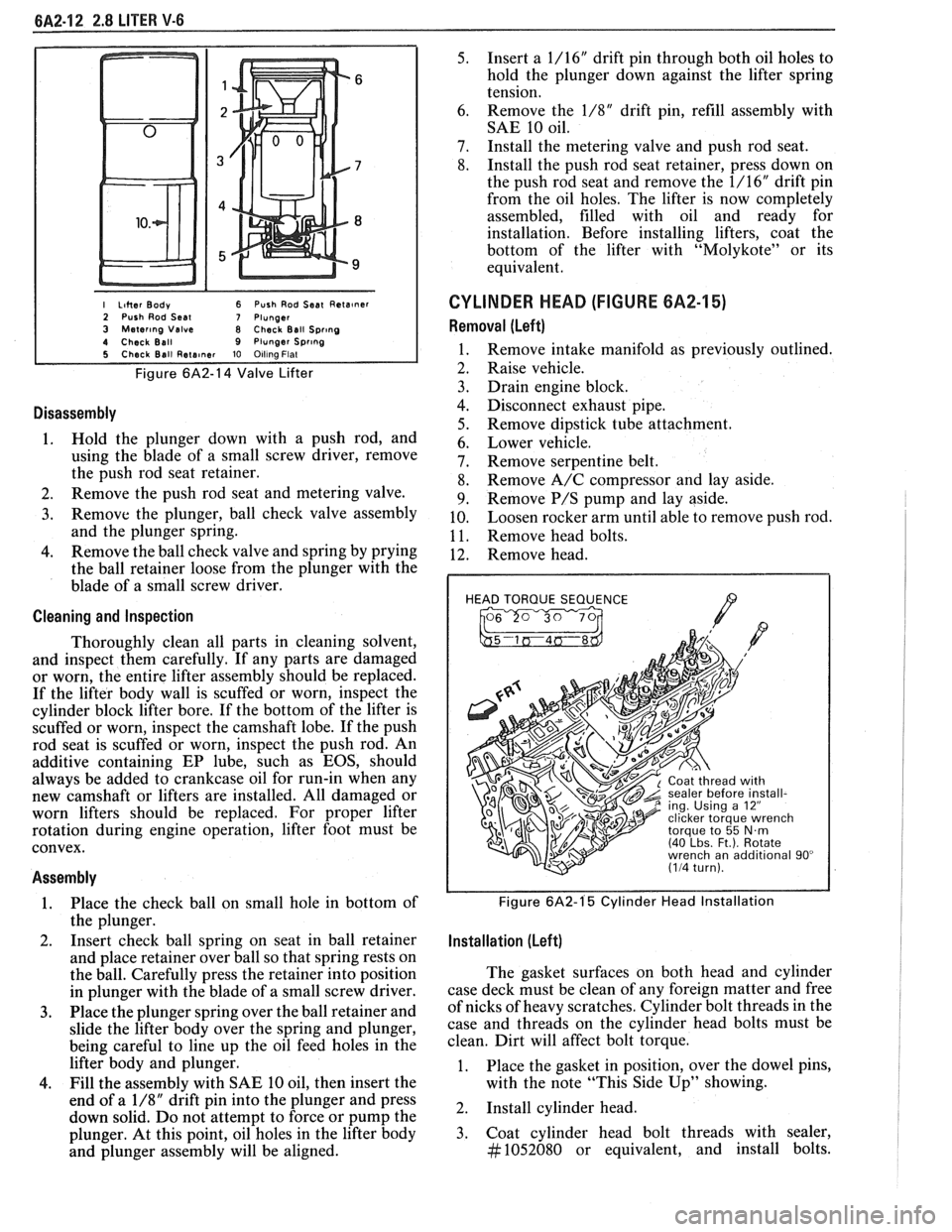
I Liher Body 6 Push Rod Seat Reta~ner 2 Push Rod Seal 7 Plunger 3 Mater~ng Valve 8 Check Ball Spr~ng 4 Check Ball 9 Plunger Spr~ng 5 Check Ball Rete~ner 10 Olllna Flat
Figure 6A2-14 Valve Lifter
Disassembly
1. Hold the plunger down with a push rod, and
using the blade of a small screw driver, remove
the push rod seat retainer.
2. Remove the push rod seat and metering valve.
3. Remove the plunger, ball check valve assembly
and the plunger spring.
4. Remove the ball check valve and spring by prying
the ball retainer loose from the plunger with the
blade of a small screw driver.
Cleaning and Inspection
Thoroughly clean all parts in cleaning solvent,
and inspect them carefully. If any parts are damaged
or worn, the entire lifter assembly should be replaced.
If the lifter body wall is scuffed or worn, inspect the
cylinder block lifter bore. If the bottom of the lifter is
scuffed or worn, inspect the camshaft lobe. If the push
rod seat is scuffed or worn, inspect the push rod. An
additive containing EP lube, such as EOS, should
always be added to crankcase oil for run-in when any
new camshaft or lifters are installed. All damaged or
worn lifters should be replaced. For proper lifter
rotation during engine operation, lifter foot must be
convex.
Assembly
1. Place
the check ball on small hole in bottom of
the plunger.
2. Insert
check ball spring on seat in ball retainer
and place retainer over ball so that spring rests on
the ball. Carefully press the retainer into position
in plunger with the blade of a small screw driver.
3. Place the plunger spring over the ball retainer and
slide the lifter body over the spring and plunger,
being careful to line up the oil feed holes in the
lifter body and plunger.
4. Fill the assembly with SAE 10 oil, then insert the
end of a
1/8" drift pin into the plunger and press
down solid. Do not attempt to force or pump the
plunger. At this point, oil holes in the lifter body
and plunger assembly will be aligned.
5. Insert a 1/16" drift pin through both oil holes to
hold the plunger down against the lifter spring
tension.
6. Remove
the
1/8" drift pin, refill assembly with
SAE 10 oil.
7. Install the metering valve and push rod seat.
8. Install the push rod seat retainer, press down on
the push rod seat and remove the 1/16" drift pin
from the oil holes. The lifter is now completely
assembled, filled with oil and ready for
installation. Before installing lifters, coat the
bottom of the lifter with "Molykote" or its
equivalent.
CYLINDER HEAD (FIGURE 6A2-15)
Removal (Left)
Remove intake manifold as previously outlined.
Raise vehicle.
Drain engine block.
Disconnect exhaust pipe.
Remove dipstick tube attachment.
Lower vehicle.
Remove serpentine belt.
Remove A/C compressor and lay aside.
Remove
P/S pump and lay aside.
Loosen rocker arm until able to remove push rod.
Remove head bolts.
Remove head.
HEAD TORQUE SEQUENCE
/7 , 2 ing. Using a 12"
Figure 6A2-1'5 Cylinder Head Installation
Installation (Left)
The gasket surfaces on both head and cylinder
case deck must be clean of any foreign matter and free
of nicks of heavy scratches. Cylinder bolt threads in the
case and threads on the cylinder head bolts must be
clean. Dirt will affect bolt torque.
1. Place the gasket in position, over the dowel pins,
with the note "This Side Up" showing.
2. Install cylinder head.
3. Coat cylinder head bolt threads with sealer,
#1052080 or equivalent, and install bolts.