1988 PONTIAC FIERO air conditioning
[x] Cancel search: air conditioningPage 1384 of 1825
AIR CONDITIONING: COMPRESSOR CONTROLS
667, ELECTRONIC
r If both switches are good but battery volt-
age is not present at the
A/C Compressor
Control Relay, check the wiring between
switches for an open (see schematic).
SYSTEM DlPaGNOSlS
V8 VINF, V8 VIN 8
s Use the Isolation Test below to choose the
proper diagnostic tests.
r Tests follow the Isolation Test.
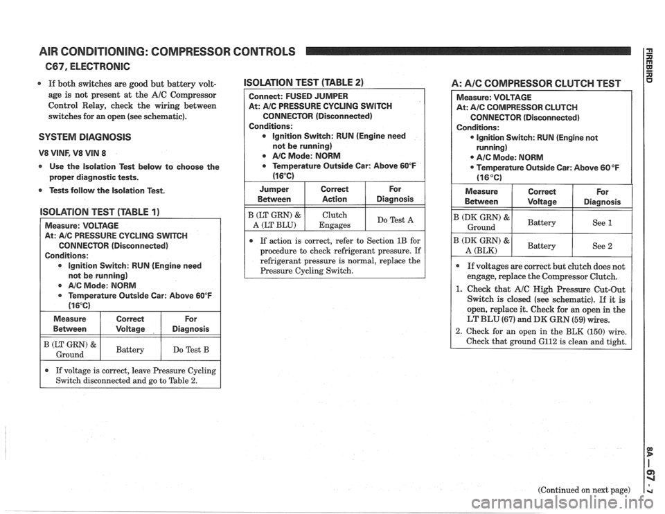
lSOLATlON TEST (TABLE 2)
Connect: FUSED JUMPER
At:
A/C PRESSURE CYCLING SWITCH
CONNECTOR (Disconnected)
Conditions: Ignition Switch: RUN (Engine need
not be running)
Q NC Mode: NORM
Q Temperature Outside Car: Above 60°F
(1 6°C)
I Jumper I Correct I For
lSOLATlOlU TEST (TABLE 1)
I Measure: VOLTAGE
AIC Mode:
NORM
@ Temperature Outside Car: Above 60°F
(1 6°C)
At:
AIC PRESSURE
CYCLING SWITCH
CONNECTOR (Disconnected)
Conditions:
lgnition Switch: RUN (Engine need
not be running) Between
B (LT GRN) &
A (LT
BLU)
If action is correct, refer to Section 1B for
procedure to check refrigerant pressure. If
refrigerant pressure is
normal, replace the
I (zz) & I Battery I Do Test B I
Measure
Between
A: AIC COMPRESSOR CLUTCH TEST
Action
Clutch
Engages
Diagnosis
Do Test A
Correct
Voltage
.
If voltage is correct, leave Pressure Cycling
Switch disconnected and go to Table
2.
Measure: VOLTAGE
At:
A/C COMPRESSOR CLUTCH
CONNECTOR (Disconnected)
Conditions:
lgnition Switch: RUN (Engine not
running)
0 A/C Mode: NORM
Temperature Outside Car: Above
60°F
(16°C)
For
Diagnosis
(Continued on next page)
Measure
Betvveen
B (DK GRN) &
Ground
B (DK GRN) &
A (BLK)
Q If voltages are correct but clutch does not
engage, replace the Compressor Clutch.
1. Check that A/C Nigh Pressure Cut-Out
Switch is closed (see schematic).
If it is
open, replace it. Check for
an open in the
LT BLU (67) and DK GRN (59) wires.
2. Check for an open in the BLK (150) wire.
Check that ground 6112 is clean and tight.
Correct
\joltage
Battery
Battelr
For
Diagnosis
See 1
See 2
Page 1385 of 1825
AIR CONDITIONING: COMPRESSOR CONTROLS
C67, ELECTRONIC
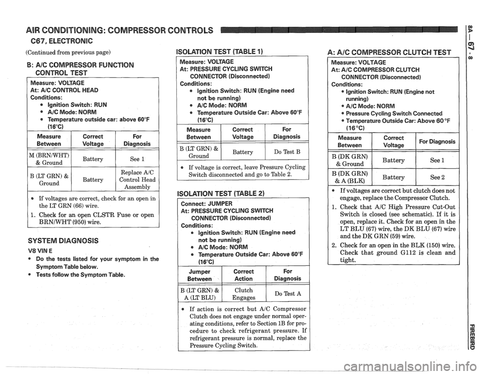
(Continued from previous page) ISOLATION TEST (TABLE 1) A: AIC COMPRESSOR CLUTCH TEST 1
B: A/C COMPRESSOR FUNCTION
CONTROL TEST
At: AIC CONTROL HEAD
Conditions:
@ lgnition Switch: RUN
AIC Mode: NORM
Temperature outside car: above 60°F
I (16°C)
Measure
Between
-
Replace AJC
M (BRNIWHT)
& Ground
If voltages are correct, check for an open
in
the LT GRN (66) wire.
1. Check for an open CLSTR Fuse or open
BRNIWRT (950) wire.
Correct
Voltage
SYSTEM DIAGNOSIS
For
Diagnosis
Battery
Do the tests listed for your symptom in the
Symptom Table below.
Tests follow the Symptom Table.
See 1
Measure: VOLTAGE
At: PRESSURE CYCLING SWITCH
CONNECTOR (Disconnected)
Conditions: lgnition Switch: RUN (Engine need
not be running)
AIC Mode: NORM
a Temperature Outside Car: Above 60°F
(16°C)
I Measure ( Correct ( For (
Between I Voltage 1 Diagnosis I
1 If voltage is correct, leave Pressure Cycling 1
B (LT GRN) &
Ground
Switch disconnected and go to Table 2.
lSOLATlON TEST (TABLE 2)
Battery
Connect: JUMPER
At: PRESSURE CYCLING
SWITCH
CONNECTOR (Disconnected)
Conditions: lgnition Switch: RUN (Engine need
not be running)
@ AIC Mode: NORM
a Temperature Outside Gar: Above 60°F
Do Test B
I Between I Action I Diagnosis I
(16°C)
a If action is correct but A/C Compressor
Clutch does not engage under normal oper-
ating conditions, refer to Section
1B for pro-
cedure to check refrigerant pressure. If
refrigerant pressure is normal, replace the
Pressure
Cycling Switch.
For Jum~er
B (LT GRN) &
A (LT BLU)
At: Ale COMPRESSOR CLUTCH
CONNECTOR (Disconnected)
@ lgnition Switch: RUN (Engine not
@ AIC Mode: NORM
Pressure Cycling Switch Connected
Temperature Outside Car: Above
60°F
1. Check that AIC High Pressure Cut-Out
Switch
is closed (see schematic). If it is
open, replace it. Check for
an open in the
LT BLU (67) wire, the DK BLU (67) wire
and the
DK GRN (59) wire.
2. Check for
an open in the BLK (150) wire.
Check that ground 6112 is clean and
Correct
.
Clutch
Engages Do
Test A
Page 1386 of 1825
AIR CONDITIONING: COMPRESSOR CONTROLS
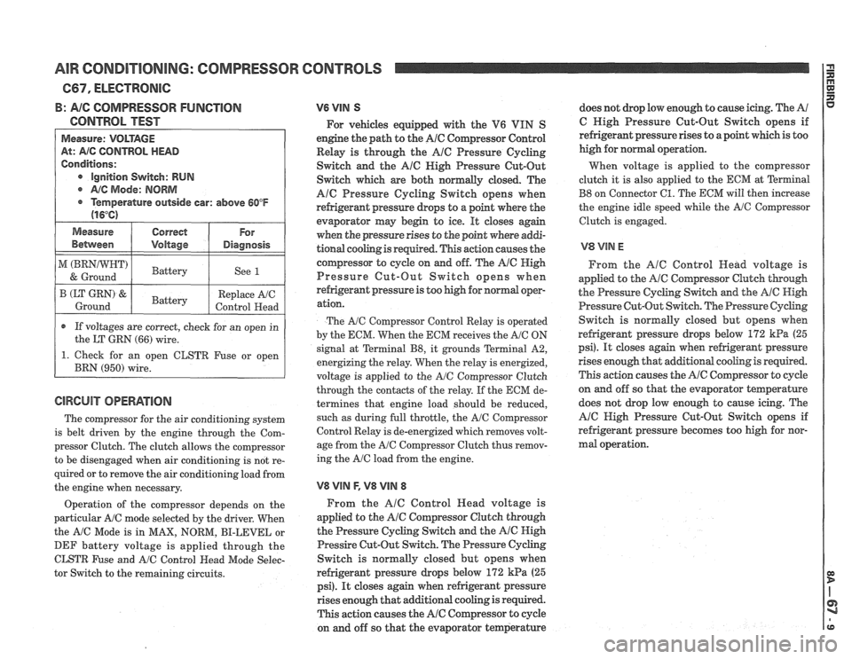
B: AIG COMPRESSOR FUNGTlON
CONTROL TEST
Measure: VOLTAGE
At: AIG CONTROL HEAD
Conditions:
e Ignition Switch: RUN
@ A/C Mode: NORM
@ Temperature outside car: above 60°F
(16°C)
1 Measure I Correct 1 For 1
Between I Voltage I Diagnosis I
1 ) 1 Battery 1 See 1 I
r If voltages are correct, check for an open in
the LT
GRN (66) wire.
B (LT GRN) &.
Ground
1. Check for an open CLSTR Fuse or open
BRN
(950) wire.
The compressor for the air conditioning system
is belt driven by the engine through the Com-
pressor Clutch. The clutch allows the compressor
to be disengaged when air conditioning is not re-
Battery
quired or to remove the air conditioning load from
the engine when necessary. Replace
A/C
Control Head
Operation of the compressor depends on the
particular A/C mode selected by the driver. When
the
A/C Mode is in MAX, NORM, BI-LEVEL or
DEF battery voltage is applied through the
CLSTR Fuse and
A/C Control Head Mode Selec-
tor Switch to the remaining circuits.
V6 VIN S
For vehicles equipped with the V6 VIN S
engine the path to the
A/C Compressor Control
Relay is through the
AlC Pressure Cycling
Switch and the
A16 Nigh Pressure Cut-Out
Switch which are both normally closed. The
Ale Pressure Cycling Switch opens when
refrigerant pressure drops to a point where the
evaporator may begin to ice.
It closes again
when the pressure rises to the point where
addi-
tional cooling is required. This action causes the
compressor to cycle on and off. The
Ale High
Pressure Cut-Out Switch opens when
refrigerant pressure is too high for
nomd oopr-
ation.
The AIC Compressor Control Relay is operated
by the EGM. When the ECM receives the
A/C ON
signal at Terminal
B8, it grounds Terminal A2,
energizing the relay. When the relay is energized,
voltage is applied to the
A/C Compressor Clutch
through the contacts of the relay. If the ECM de-
termines that engine load should be reduced,
such as during full throttle, the
A/C Compressor
Control Relay is de-energized which removes volt-
age from the
A/C Compressor Clutch thus remov-
ing the
A/C load from the engine.
V8 VlN F, V8 VllU 8
From the AlC Control Head voltage is
applied to the
A/@ Cornpressor Clutch through
the Pressure Cycling Switch and the
A/@ High
Pressire Cut-Out Switch. The Pressure Cycling
Switch is normally closed but opens when
refrigerant pressure drops below
172 kPa (25
psi). It closes again when refrigerant pressure
rises enough that additional cooling is required.
This action causes the
A/C Compressor to cycle
on and off so that the evaporator temperature does
not drop low enough to cause icing. The
A/
C High Pressure Cut-Out Switch opens if
refrigerant pressure rises to a point which is too
high for normal operation.
When voltage is applied to the compressor
clutch it is also applied to the ECM at
Terminal
B8 on Connector 61. The ECM will then increase
the engine idle speed while the
A/G Compressor
Clutch is engaged.
From the
AlC Control Head voltage is
applied to the
A/C Compressor Clutch though
the Pressure Cycling Switch and the AIC High
Pressure Cut-Out Switch. The Pressure
Cychg
Switch is normally closed but opens when
refrigerant pressure
drops below 172 kPa (25
psi). It closes again when refrigerant pressure
rises enough that
additional cooling is required.
This action causes the
A/C Compressor to cyde
on and off so that the evaporator teqerature
does not drop low enough to cause icing. The
A/C High Pressure Cut-Out Switch opens if
refrigerant pressure becomes too high for nor-
mal operation.
Page 1387 of 1825
AIR CONDITIONING: AIR DELIVERY
!E 667, ELECTRONIC I
FUSE - BLOCK - TEMPERATURE YELLOW
SELECTOR WIRE (996)
FULLY COLD GREATER THAN
BATTERY VOLTAGE
MINUS
0.3 VOLTS
FULLY HOT LESS THAN
0.3 VOLTS
Page 1389 of 1825
AIR CONDITIONING: AIR DELIVERY I g
667, ELECTRONIC
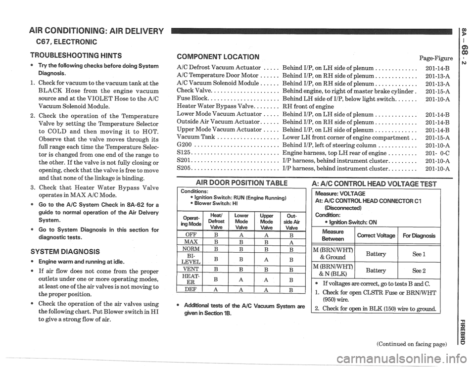
TROUBLESHOOTING
HINTS
Try the following checks before doing System
Diagnosis.
1. Check for vacuum to the vacuum tank at the
BLACK Hose from the engine vacuum
source and at the VIOLET Rose to the
AIC
Vacuum Solenoid Module.
Check the operation of the Temperature
Valve by setting the Temperature Selector
to COLD and then moving it to ROT.
Observe that the valve moves through its
full range each time the Temperature Selec-
tor is changed from one end of the range to
the other. If the valve is not fully closing or
opening, check that the valve is free to move
and that none of the linkage is binding.
3. Check that Heater Water Bypass Valve
operates in MAX
AIC Mode.
Go to the AIC System Check in 8A-62 for a
guide to normal operation of the Air
Delvery
System.
Go to System Diagnosis
in this section for
diagnostic tests.
SYSTEM DIAGNOSIS
Engine warm and running at idle.
If air flow does not come from the proper
outlets under one or more operating modes,
at least one of the air valves is not moving to
the proper position.
@ Check the operation of the air valves using
the following chart. Put Blower switch in
HI
to give a strong flow of air.
COMPONENT LOCATION Page-Figure
AIC Defrost Vacuum Actuator ..... Behind IIP, on LH side of plenum .............
AIC Temperature Door Motor ...... Behind IIP, on RH side of plenum. ............
AIC Vacuum Solenoid Module ...... Behind IIP, on RH side of plenum. ............
Check Valve. .................... Behind engine, to right of master brake cylinder.
Fuse Block.
..................... Behind LH side of IIP, below light switch. ......
Neater Water Bypass Valve. ....... RH front of engine
Lower Mode Vacuum Actuator
..... Behind IIP, on LH side of plenum .............
Outside Air Vacuum Actuator. ..... Behind IIP, on RH side of plenum. ............
Upper Mode Vacuum Actuator ..... Behind IIP, on LH side of plenum .............
.. Vacuum Tank ................... Lower LH front corner of engine compartment
6200
.......................... Behind IIP, left of steering column ............
S125. .......................... Engine harness, top LH rear of engine .........
........ S201. .......................... IIP harness, behind instrument cluster.
........ S205. .......................... IIP harness, behind instrument cluster.
(Disconnected)
Condition:
IgnEon Swgch: ON
AIR DOOR POSITION TABLE A: AIC CONTROL HEAD VOLTAGE TEST
Measure
Between I Correct Vdtage / For Diagmsk I
Conditions: ignition Switch: RUN (Engine Running)
Blower Switch: HI
I"(BRNIWIFDI & Ground Battery ( See1 I
Measure: VOLTAGE
At:
A/C CONTROL HEAD CONNECTOR 61
I I
@ If voltages are correct, go to tests B and C.
(Continued on facing page)
Mdifional tests of the AIC Vacum System are
(950) wire.
2- ~hd for op in BLK (150) rrire to given in Seclion 1B.
Page 1391 of 1825
AIR CONDITIONING: AIR DELIVERY
(Continued from previous page)
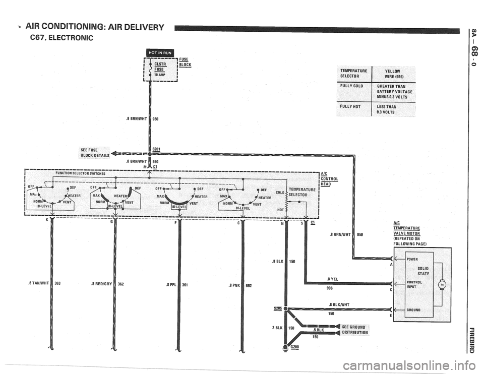
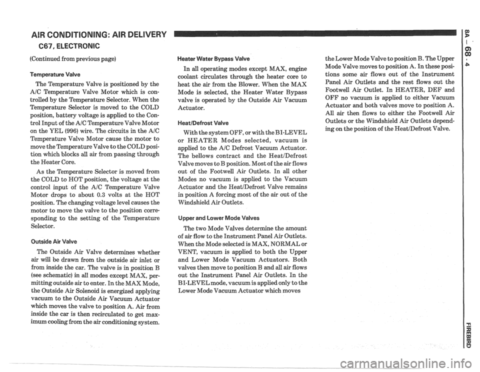
Temperature Valve
The Temperature Valve is positioned by the
A/C Temperature Valve Motor which is con-
trolled by the Temperature Selector. When the
Temperature Selector is moved to the COLD
position, battery voltage is applied to the Con-
trol Input of the
AIC Temperature Valve Motor
on the YEL
(996) wire. The circuits in the Ale
Temperature Valve Motor cause the motor to
move the Temperature Valve to the COLD posi-
tion which blocks all air from passing through
the Heater Core.
As the Temperature Selector is moved from
the COLD to ROT position, the voltage at the
control input of the
AIC Temperature Valve
Motor drops to about
0.3 volts at the HOT
position. The changing voltage level causes the
motor to move the valve to the position corre-
sponding to the setting of the Temperature
Selector.
Outside Air Valve
The Outside Air Valve determines whether
air will be drawn from the outside air inlet or
from inside the car. The valve is in position
B
(see schematic) in all modes except MAX, per-
mitting outside air to enter. In the MAX Mode,
the Outside Air Solenoid is energized applying
vacuum to the Outside Air Vacuum Actuator
which moves the valve to position A. Air from
inside the car is then recirculated to get max-
imum cooling from the
air conditioning system.
Heater Water Bypass Valve
In all operating modes except MAX, engine
coolant circulates through the heater core to
heat the
air from the Blower. When the MAX
Mode is selected, the
Neater Water Bypass
valve is operated by the Outside Air Vacuum
Actuator.
HeatIDefrost Valve
With the system OFF, or with the BI-LEVEL
or HEATER Modes selected, vacuum is
applied to the
AIC Defrost Vacuum Actuator.
The bellows contract and the
HeatIDefrost
Valve moves to B position. Most of the air flows
out of the
Footwell Air Outlets. In all other
Modes no vacuum is applied to the Vacuum
Actuator and the
HeatIDefrost Valve remains
in position A forcing most of the air out of the
Windshield Air Outlets.
Upper and Lower Mode Valves
The two Mode Valves determine the amount
of
air flow to the Instrument Panel Air Outlets.
When the Mode selected is MAX, NORMAL or
VENT, vacuum is applied to both the Upper
and Lower Mode Vacuum Actuators. Both
valves then move to position
B and all air flows
out the Instrument Panel Air Outlets. In the
BI-LEVEL mode,
vacuumis applied only to the
Lower Mode Vacuum Actuator which moves the
Lower Mode Valve to position
B. The Upper
Mode Valve moves to position
A. In these posi-
tions some air flows out of the Instrument
Panel Air Outlets and the rest flows out the
Footwell Air Outlet. In HEATER, DEF and
OFF no vacuum is applied to either Vacuum
Actuator and both valves move to position A.
AU. air then flows to either the Footwell Air
Outlets or the Windshield Air Outlets depend-
ing on the position of the
NeatIDefrost Valve.
Page 1650 of 1825
RADIO SYSTEMS AND ANTENNAS 9A-1
SECTION 9A
0 SYSTEMS AND ANTENNAS
CONTENTS
............................................. General Description .................................... 9A-1 Radio Operation 9A-4
Radio
............................................................ 9A-1 ETR AM/FM Stereo (UM-7) ....................... 9A-4
Antennas
........................................................ 9A- 1 ETR Stereo Cassette (UM-6) ......................... 9A-5
Fixed Antenna
.......................................... 9A- 1 ETR Stereo/Cassette/Eaualizer
Diagnosis ........................................................
Radio ....................... .. ................................
Static and Noise .................................... .....
........................................ Popping Noise
Preliminary Diagnostics
.............................
Antenna ................................. .. ................
Tape Player .................. .... .......................
Service Procedures ....................................
Radio and Speakers ........................... .............
Radio Noise Suppression Equipment ............
Stereo Cassette Tape Player ..........................
Tape & Tape Player Care ........................
(UX-1) ..................................................... 9A-6
Advanced ETR
Stereo/Cassette/Equalizer Touch
Control
.................................... ... .............. 9A-7
On-Car Service .............................................. 9A-9
Radio Receiver
............................................ 9A-9
Radio Steering Wheel Controls
..................... 9A-9
Audio Amplifier
........................................... 9A-9
Radio Suppression
..................................... 9A-9
Front Speaker
................................................. 9A-9
............... Rear Speaker; Sub Woofer Speaker
9A-9
Antenna
..................... .. ............................. 9A- 10
GENERAL DESCRIPUION
RADIO ANTENNAS
For radios and radio use see the "Radio Fixed Antenna
Operation" section. ETR means 'Electronically Tuned The
fixed antenna on the right front fender
Receiver'. cannot be adjusted up or down. It may provide
improved reception in rural areas.
- The fixed antenna is designed to withstand most
car washes without damage. If the antenna becomes
slightly bent, you can straighten it by hand. The
antenna can be replaced if severely bent (by vandalism,
etc.). Antennas must be kept clean for good
performance.
RADIO
Because radio problems are normally repaired at
authorized warranty repair stations, the tendency is to
remove the set when a problem is reported, without any
preliminary diagnosis. This results in a large number
of radios being "No Trouble Found" units when
received by the warranty repair stations. Often the
trouble can be corrected without radio removal. wire.
If equipped with
A/C, the blower motor has a
built-in capacitor. Extra electrical equipment added to
the static if not properly grounded or wiring was
improperly routed.
Weak
FM station reception will be affected by
nearby buildings, car speed and direction. These
"flutter" and "fading" conditions are characteristic of
weak FM signals.
ETR radios require clock and button reset if the
battery is disconnected.
Popping Noise
Static and Noise Operating devices such as turn signals, pushing in
cigarette lighter, operating stop lights, etc., may cause
Ground strap connections must be clean and
a popping noise on distant (weak) AM signals.
tight, spark plug cables must be TVRS type and in
good condition and resistance-type spark plugs used.
Preliminary Diagnostics
Capacitors are used in the generator, heating/air
conditioning system, and fuse panel to reduce noise
The inconvenience of driving without a radio
entering the radio through the feed wires. If the car has
while the set is being serviced can often be avoided if
a heater only, the capacitor is in the blower motor feed
the following quick checks are used to eliminate
Page 1710 of 1825
FRONT END - F STYLE 41-1-1
SECTION 4H
FRONT END
NOTICE: The anti-theft label found on some major sheet metal, engines, and transmissions must be masked
prior to painting, rustproofing, undercoating, etc. The
mask must be removed following the above operations.
Failure to keep the label clean and readable may result in liability for violation of Federal Vehicle Theft Prevention
Standard, and subject the vehicle owner to possible suspicion that the part was stolen.
CONTENTS
.............................................................................................................. Body Ventilation 4H- 1
Shroud Side Trim Finishing Panel ................................................................................ 4H- 1
Pressure Relief Valve .................................................................................................. 4H- 1
Hood Latch Release Cable ............................................................................................ 4H- 1
The body ventilation system on styles without air
conditioning consists of a fresh air intake located at the
front plenum chamber. Air enters the front plenum
chamber through an air intake grille screen (Fig.
1).
Air passes through the plenum chamber to air outlet
doors. When ventilation controls are operated, air
enters past the doors and into the body from outlets in
the dash panel. The air then passes through the body,
around the rear seat, into the rear compartment to the
rear quarters and leaves the body passing through the
pressure relief valves on the rear body lock pillars (Fig.
4). For complete instructions on operation of the body
ventilation system, refer to the owner's manual.
Water entering the plenum chamber is drained
through openings provided for that purpose.
FRONT END SEALING
All potential waterleak locations are sealed in
production with high quality durable sealers. Should it
be necessary to reseal specific areas, a high quality
medium-bodied sealer which will remain flexible after
curing and can be painted should be used.
SHROUD SIDE TRIM FINISHING PANEL
Removal and Installation
1. Remove shroud side trim finishing panel screws
(Fig. 2).
2. Pull down and rearward on trim finishing panel
to release hood cable handle from slot on left side.
On right side, pull rearward to remove panel from
windshield lower side garnish (Figs.
2 and 3).
3. To install, reverse removal procedures.
PRESSURE RELIEF VALVE
The pressure relief valves are attached to rear
lock pillars (in door opening below belt) with screws.
Figure
4 shows pressure relief valve installations.
Removal and Installation
1. Remove louver-to-lock pillar screw located in the
door opening (Fig.
4).
2. Slide louver up to disengage hook-type attaching
clip to complete removal.
3. To install, reverse removal procedure.
HOOD LATCH RELEASE CABLE
The one-piece hood latch release cable includes
pull handle, control cable and housing. The control
cable is installed through the left shroud side trim
panel. A sealing grommet attached to the dash panel
completes the assembly (Figs. 2 and
5).
Removal and Installation
The shroud side finishing panels are designed
with an integral hinge pillar pinchweld finishing lace.
The left side has a cutout slot for the hood release cable
handle. There is no need to remove the cable assembly
2.
when removing the trim finishing panel. The trim 3.
finishing panel is secured to the side shroud with
self-tapping attaching screws.
4.
Raise hood and disengage cable from hood latch
assembly. Block latch to prevent hood locking
until cable has been reinstalled.
Remove left shroud side trim panel.
Disengage control assembly housing from cutout
of trim panel and remove
cable assembly from
panel.
To install, reverse the removal procedure.