1988 OPEL CALIBRA brake sensor
[x] Cancel search: brake sensorPage 141 of 525
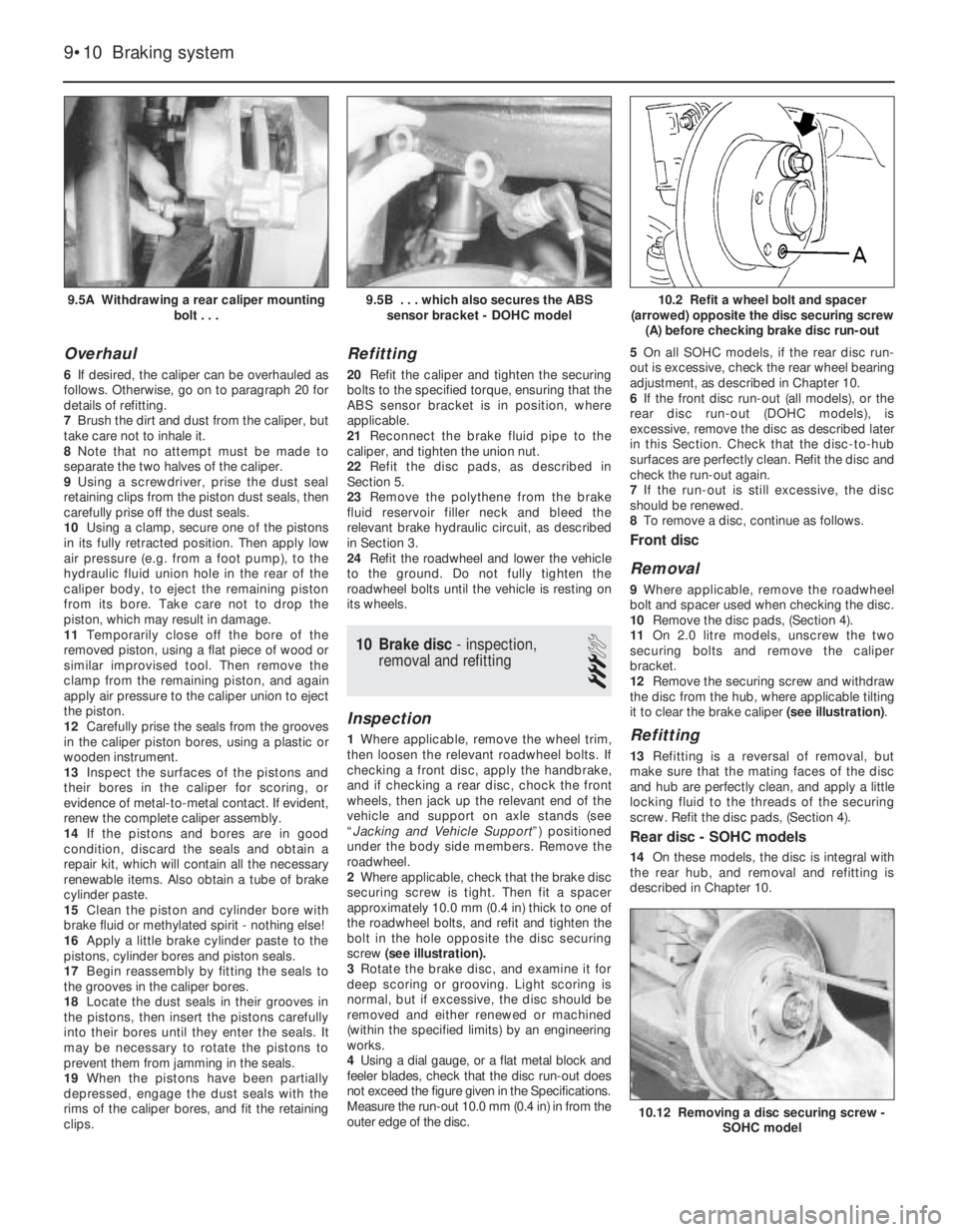
Overhaul
6If desired, the caliper can be overhauled as
follows. Otherwise, go on to paragraph 20 for
details of refitting.
7Brush the dirt and dust from the caliper, but
take care not to inhale it.
8Note that no attempt must be made to
separate the two halves of the caliper.
9Using a screwdriver, prise the dust seal
retaining clips from the piston dust seals, then
carefully prise off the dust seals.
10Using a clamp, secure one of the pistons
in its fully retracted position. Then apply low
air pressure (e.g. from a foot pump), to the
hydraulic fluid union hole in the rear of the
caliper body, to eject the remaining piston
from its bore. Take care not to drop the
piston, which may result in damage.
11Temporarily close off the bore of the
removed piston, using a flat piece of wood or
similar improvised tool. Then remove the
clamp from the remaining piston, and again
apply air pressure to the caliper union to eject
the piston.
12Carefully prise the seals from the grooves
in the caliper piston bores, using a plastic or
wooden instrument.
13Inspect the surfaces of the pistons and
their bores in the caliper for scoring, or
evidence of metal-to-metal contact. If evident,
renew the complete caliper assembly.
14If the pistons and bores are in good
condition, discard the seals and obtain a
repair kit, which will contain all the necessary
renewable items. Also obtain a tube of brake
cylinder paste.
15Clean the piston and cylinder bore with
brake fluid or methylated spirit - nothing else!
16Apply a little brake cylinder paste to the
pistons, cylinder bores and piston seals.
17Begin reassembly by fitting the seals to
the grooves in the caliper bores.
18Locate the dust seals in their grooves in
the pistons, then insert the pistons carefully
into their bores until they enter the seals. It
may be necessary to rotate the pistons to
prevent them from jamming in the seals.
19When the pistons have been partially
depressed, engage the dust seals with the
rims of the caliper bores, and fit the retaining
clips.
Refitting
20Refit the caliper and tighten the securing
bolts to the specified torque, ensuring that the
ABS sensor bracket is in position, where
applicable.
21Reconnect the brake fluid pipe to the
caliper, and tighten the union nut.
22Refit the disc pads, as described in
Section 5.
23Remove the polythene from the brake
fluid reservoir filler neck and bleed the
relevant brake hydraulic circuit, as described
in Section 3.
24Refit the roadwheel and lower the vehicle
to the ground. Do not fully tighten the
roadwheel bolts until the vehicle is resting on
its wheels.
10Brake disc - inspection,
removal and refitting
3
Inspection
1Where applicable, remove the wheel trim,
then loosen the relevant roadwheel bolts. If
checking a front disc, apply the handbrake,
and if checking a rear disc, chock the front
wheels, then jack up the relevant end of the
vehicle and support on axle stands (see
“Jacking and Vehicle Support”) positioned
under the body side members. Remove the
roadwheel.
2Where applicable, check that the brake disc
securing screw is tight. Then fit a spacer
approximately 10.0 mm (0.4 in) thick to one of
the roadwheel bolts, and refit and tighten the
bolt in the hole opposite the disc securing
screw (see illustration).
3Rotate the brake disc, and examine it for
deep scoring or grooving. Light scoring is
normal, but if excessive, the disc should be
removed and either renewed or machined
(within the specified limits) by an engineering
works.
4Using a dial gauge, or a flat metal block and
feeler blades, check that the disc run-out does
not exceed the figure given in the Specifications.
Measure the run-out 10.0 mm (0.4 in) in from the
outer edge of the disc. 5On all SOHC models, if the rear disc run-
out is excessive, check the rear wheel bearing
adjustment, as described in Chapter 10.
6If the front disc run-out (all models), or the
rear disc run-out (DOHC models), is
excessive, remove the disc as described later
in this Section. Check that the disc-to-hub
surfaces are perfectly clean. Refit the disc and
check the run-out again.
7If the run-out is still excessive, the disc
should be renewed.
8To remove a disc, continue as follows.
Front disc
Removal
9Where applicable, remove the roadwheel
bolt and spacer used when checking the disc.
10Remove the disc pads, (Section 4).
11On 2.0 litre models, unscrew the two
securing bolts and remove the caliper
bracket.
12Remove the securing screw and withdraw
the disc from the hub, where applicable tilting
it to clear the brake caliper (see illustration).
Refitting
13Refitting is a reversal of removal, but
make sure that the mating faces of the disc
and hub are perfectly clean, and apply a little
locking fluid to the threads of the securing
screw. Refit the disc pads, (Section 4).
Rear disc - SOHC models
14On these models, the disc is integral with
the rear hub, and removal and refitting is
described in Chapter 10.
9•10Braking system
9.5A Withdrawing a rear caliper mounting
bolt . . .10.2 Refit a wheel bolt and spacer
(arrowed) opposite the disc securing screw
(A) before checking brake disc run-out
10.12 Removing a disc securing screw -
SOHC model
9.5B . . . which also secures the ABS
sensor bracket - DOHC model
Page 144 of 525
14Front brake disc shield -
removal and refitting
3
Removal
1Where applicable, remove the wheel trim,
then loosen the relevant front roadwheel bolts
and apply the handbrake. Jack up the front of
the vehicle, and support on axle stands (see
“Jacking and Vehicle Support”) positioned
under the body side members. Remove the
roadwheel.
2Remove the brake disc, as described in
Section 10.
3Using a screwdriver inserted through the
holes in the hub flange, extract the three
screws securing the disc shield to the hub
carrier.
4Using plate shears or an alternative tool, cut
a section of metal from the rear edge of the
shield to enable the shield to be withdrawn
over the hub, then remove the shield (see
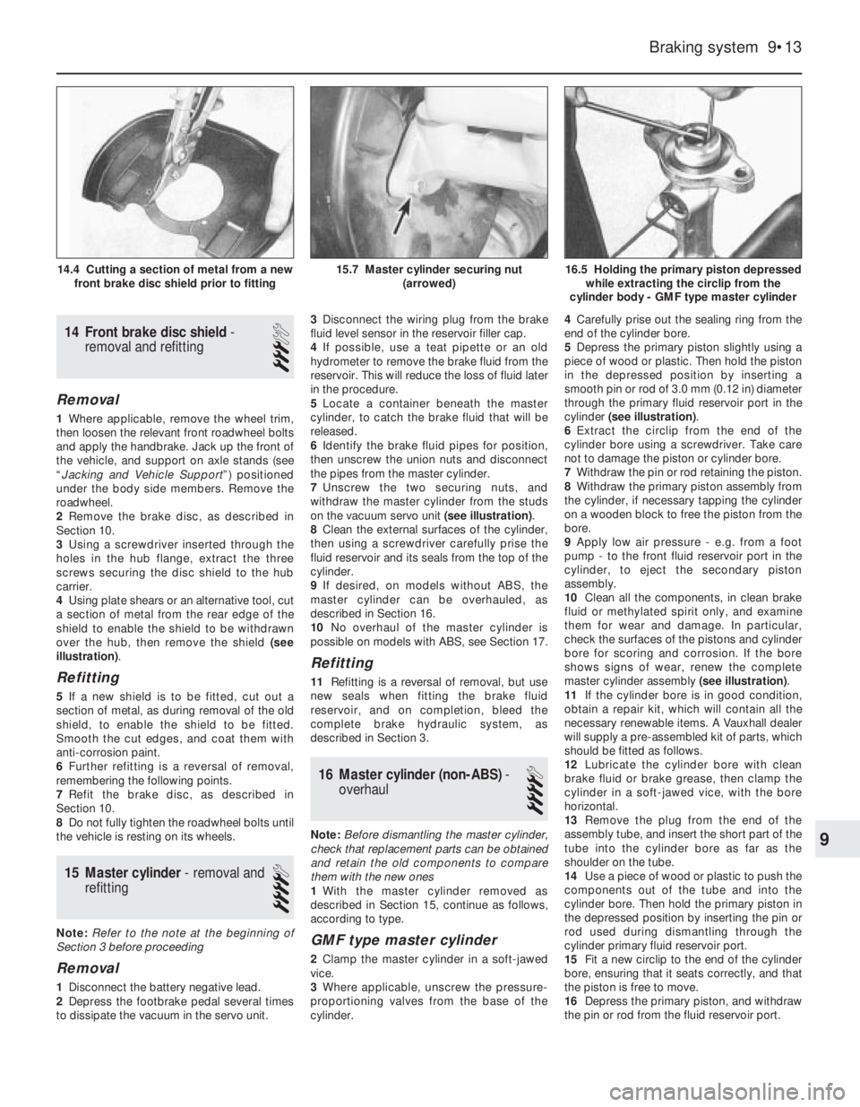
illustration).
Refitting
5If a new shield is to be fitted, cut out a
section of metal, as during removal of the old
shield, to enable the shield to be fitted.
Smooth the cut edges, and coat them with
anti-corrosion paint.
6Further refitting is a reversal of removal,
remembering the following points.
7Refit the brake disc, as described in
Section 10.
8Do not fully tighten the roadwheel bolts until
the vehicle is resting on its wheels.
15Master cylinder - removal and
refitting
4
Note: Refer to the note at the beginning of
Section 3 before proceeding
Removal
1Disconnect the battery negative lead.
2Depress the footbrake pedal several times
to dissipate the vacuum in the servo unit.3Disconnect the wiring plug from the brake
fluid level sensor in the reservoir filler cap.
4If possible, use a teat pipette or an old
hydrometer to remove the brake fluid from the
reservoir. This will reduce the loss of fluid later
in the procedure.
5Locate a container beneath the master
cylinder, to catch the brake fluid that will be
released.
6Identify the brake fluid pipes for position,
then unscrew the union nuts and disconnect
the pipes from the master cylinder.
7Unscrew the two securing nuts, and
withdraw the master cylinder from the studs
on the vacuum servo unit (see illustration).
8Clean the external surfaces of the cylinder,
then using a screwdriver carefully prise the
fluid reservoir and its seals from the top of the
cylinder.
9If desired, on models without ABS, the
master cylinder can be overhauled, as
described in Section 16.
10No overhaul of the master cylinder is
possible on models with ABS, see Section 17.
Refitting
11Refitting is a reversal of removal, but use
new seals when fitting the brake fluid
reservoir, and on completion, bleed the
complete brake hydraulic system, as
described in Section 3.
16Master cylinder (non-ABS) -
overhaul
4
Note: Before dismantling the master cylinder,
check that replacement parts can be obtained
and retain the old components to compare
them with the new ones
1With the master cylinder removed as
described in Section 15, continue as follows,
according to type.
GMF type master cylinder
2Clamp the master cylinder in a soft-jawed
vice.
3Where applicable, unscrew the pressure-
proportioning valves from the base of the
cylinder.4Carefully prise out the sealing ring from the
end of the cylinder bore.
5Depress the primary piston slightly using a
piece of wood or plastic. Then hold the piston
in the depressed position by inserting a
smooth pin or rod of 3.0 mm (0.12 in) diameter
through the primary fluid reservoir port in the
cylinder (see illustration).
6Extract the circlip from the end of the
cylinder bore using a screwdriver. Take care
not to damage the piston or cylinder bore.
7Withdraw the pin or rod retaining the piston.
8Withdraw the primary piston assembly from
the cylinder, if necessary tapping the cylinder
on a wooden block to free the piston from the
bore.
9Apply low air pressure - e.g. from a foot
pump - to the front fluid reservoir port in the
cylinder, to eject the secondary piston
assembly.
10Clean all the components, in clean brake
fluid or methylated spirit only, and examine
them for wear and damage. In particular,
check the surfaces of the pistons and cylinder
bore for scoring and corrosion. If the bore
shows signs of wear, renew the complete
master cylinder assembly (see illustration).
11If the cylinder bore is in good condition,
obtain a repair kit, which will contain all the
necessary renewable items. A Vauxhall dealer
will supply a pre-assembled kit of parts, which
should be fitted as follows.
12Lubricate the cylinder bore with clean
brake fluid or brake grease, then clamp the
cylinder in a soft-jawed vice, with the bore
horizontal.
13Remove the plug from the end of the
assembly tube, and insert the short part of the
tube into the cylinder bore as far as the
shoulder on the tube.
14Use a piece of wood or plastic to push the
components out of the tube and into the
cylinder bore. Then hold the primary piston in
the depressed position by inserting the pin or
rod used during dismantling through the
cylinder primary fluid reservoir port.
15Fit a new circlip to the end of the cylinder
bore, ensuring that it seats correctly, and that
the piston is free to move.
16Depress the primary piston, and withdraw
the pin or rod from the fluid reservoir port.
Braking system 9•13
16.5 Holding the primary piston depressed
while extracting the circlip from the
cylinder body - GMF type master cylinder15.7 Master cylinder securing nut
(arrowed)14.4 Cutting a section of metal from a new
front brake disc shield prior to fitting
9
Page 145 of 525

17Fit a new sealing ring to the end of the
cylinder bore.
18Where applicable, screw the pressure-
proportioning valves into the base of the
cylinder.
19Refit the master cylinder, as described in
Section 15.
ATE type master cylinder
20Clamp the master cylinder in a soft-jawed
vice.
21Where applicable, unscrew the pressure-
proportioning valves from the base of the
cylinder.
22Carefully prise out the sealing ring from
the end of the cylinder bore.
23Depress the primary piston slightly using
a piece of wood or plastic, then extract the
circlip from the end of the cylinder bore.
24Withdraw the primary piston assembly,
noting the location of the stop washers.
25Depress the secondary piston, again
using a piece of wood or plastic, and
withdraw the stop screw from the cylinder
body (see illustration).
26Withdraw the secondary piston assembly
from the cylinder, if necessary tapping the
cylinder on a wooden block to free the piston
from the bore.
27Clean all the components, in clean brake
fluid or methylated spirit only, and examine
them for wear and damage. In particular,
check the surfaces of the pistons and cylinder
bores for scoring and corrosion. If the bore
shows signs of wear, renew the complete
master cylinder assembly (see illustration).28If the cylinder bore is in good condition,
obtain a repair kit, which will contain all the
necessary renewable items. A Vauxhall dealer
will supply a complete kit of parts, which
should be fitted as follows.
29Lubricate the cylinder bore with clean
brake fluid or brake grease, then clamp the
cylinder in a soft-jawed vice, with the bore
horizontal.
30Fit a new sealing ring to the stop screw,
then screw it into the cylinder body a little
way, but not so far that it protrudes into the
bore.
31Remove the plugs from the ends of the
assembly tube, then remove all the
components from the short part of the tube,
and push the short part into the long part until
they are flush.
32Insert the assembly tube into the cylinder
bore as far as the collar on the short sleeve.
Then use a piece of wood or plastic to push
the secondary piston assembly into the bore
until it contacts the end of the cylinder.
33Lightly tighten the stop screw, then
withdraw the piece of wood or plastic and the
assembly tube, and fully tighten the stop
screw.
34Reposition the master cylinder in the vice,
with the bore facing upwards.
35Smear the primary piston skirt and the
seal grooves with the special grease provided
in the repair kit. Fit the stop washer to the
piston.
36Adjust the assembly tube so that the end
of the long part is flush with the inner shoulder
of the short part.37Fit the front seal to the primary piston,
with the open end of the seal facing the front
of the master cylinder.
38Place the assembly tube over the cylinder
to compress the seal, insert the piston and
tube part way into the bore, and withdraw the
tube.
39Place the intermediate ring on the primary
piston, then fit the remaining seal using the
assembly tube as described previously.
40Place the stop washer as the primary
piston, then depress the piston slightly using
a piece of wood or plastic, and fit a new circlip
to the end of the cylinder bore. Ensure that the
circlip is correctly seated, and that the piston
is free to move.
41Fit a new sealing ring to the end of the
cylinder bore.
9•14Braking system
16.25 Depressing the secondary piston
while extracting the stop screw - ATE type
master cylinder
16.27 Exploded view of ATE type master
cylinder
1 Filler cap (standard)
2 Strainer
3 Filler cap (with fluid level sensor)
4 Guide sleeve for float
5 Fluid reservoir
6 Cylinder body
7 Sealing ring
8 Fluid reservoir seals
9 Stop screw
10 Repair kit assembly tube
11 Pressure-proportioning valves
16.10 Exploded view of GMF type master
cylinder
1 Filler cap (standard)
2 Filler cap (with fluid level sensor)
3 Fluid reservoir
4 Fluid reservoir retaining clips
5 Fluid reservoir seals
6 Cylinder body
7 Secondary piston and springs
8 Primary piston
9 Circlip
10 Sealing ring
11 Pressure-proportioning valves
Page 147 of 525
16If adjustment is necessary, slacken the
locknut, turn the fork to give the specified
dimension, then tighten the locknut.
17Where applicable, coat the contact faces
of the servo and the mounting bracket with
sealing compound, then refit the bracket to
the servo, and tighten the securing nuts to the
specified torque.
18Coat the threads of the servo securing
bolts with locking fluid, then fit the servo to
the bulkhead and tighten the securing bolts.
19Refit the securing bolt cover plugs to the
cowl panel.
20Refit the master cylinder to the servo, and
tighten the securing nuts to the specified
torque.
21Reconnect the vacuum pipe to the servo.
22Refit the coolant expansion tank, as
described in Chapter 3.
23Refit the windscreen wiper motor and
linkage as described in Chapter 12, then refit
the windscreen cowl panel.
24Further refitting is a reversal of removal.
On completion, test the operation of the
servo, as described in Section 18.
20ABS hydraulic modulator -
removal and refitting
4
Note: Refer to Section 2, and the note at the
beginning of Section 3, before proceeding
Removal
1Disconnect the battery negative lead.
2Remove the brake fluid reservoir cap, and
secure a piece of polythene over the filler
neck with a rubber band, or by refitting the
cap. This will reduce the loss of fluid during
the following procedure.
3Remove the securing screw, and withdraw
the plastic cover from the hydraulic
modulator.
4Remove the two clamp screws, and lift off
the modulator wiring harness clamp (see
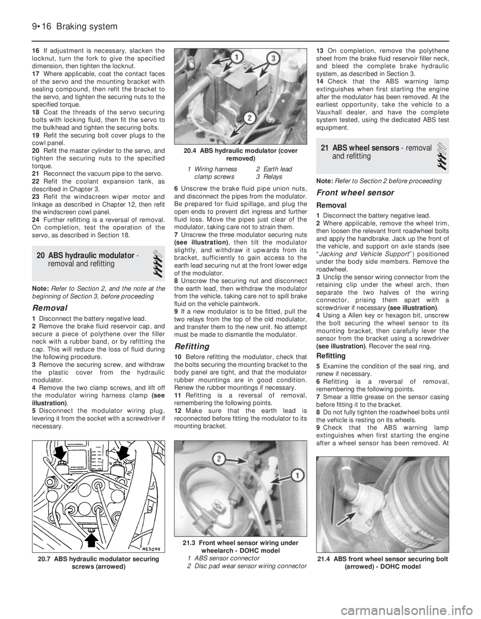
illustration).
5Disconnect the modulator wiring plug,
levering it from the socket with a screwdriver if
necessary.6Unscrew the brake fluid pipe union nuts,
and disconnect the pipes from the modulator.
Be prepared for fluid spillage, and plug the
open ends to prevent dirt ingress and further
fluid loss. Move the pipes just clear of the
modulator, taking care not to strain them.
7Unscrew the three modulator securing nuts
(see illustration), then tilt the modulator
slightly, and withdraw it upwards from its
bracket, sufficiently to gain access to the
earth lead securing nut at the front lower edge
of the modulator.
8Unscrew the securing nut and disconnect
the earth lead, then withdraw the modulator
from the vehicle, taking care not to spill brake
fluid on the vehicle paintwork.
9If a new modulator is to be fitted, pull the
two relays from the top of the old modulator,
and transfer them to the new unit. No attempt
must be made to dismantle the modulator.
Refitting
10Before refitting the modulator, check that
the bolts securing the mounting bracket to the
body panel are tight, and that the modulator
rubber mountings are in good condition.
Renew the rubber mountings if necessary.
11Refitting is a reversal of removal,
remembering the following points.
12Make sure that the earth lead is
reconnected before fitting the modulator to its
mounting bracket.13On completion, remove the polythene
sheet from the brake fluid reservoir filler neck,
and bleed the complete brake hydraulic
system, as described in Section 3.
14Check that the ABS warning lamp
extinguishes when first starting the engine
after the modulator has been removed. At the
earliest opportunity, take the vehicle to a
Vauxhall dealer, and have the complete
system tested, using the dedicated ABS test
equipment.
21ABS wheel sensors - removal
and refitting
3
Note: Refer to Section 2 before proceeding
Front wheel sensor
Removal
1Disconnect the battery negative lead.
2Where applicable, remove the wheel trim,
then loosen the relevant front roadwheel bolts
and apply the handbrake. Jack up the front of
the vehicle, and support on axle stands (see
“Jacking and Vehicle Support”) positioned
under the body side members. Remove the
roadwheel.
3Unclip the sensor wiring connector from the
retaining clip under the wheel arch, then
separate the two halves of the wiring
connector, prising them apart with a
screwdriver if necessary (see illustration).
4Using a Allen key or hexagon bit, unscrew
the bolt securing the wheel sensor to its
mounting bracket, then carefully lever the
sensor from the bracket using a screwdriver
(see illustration). Recover the seal ring.
Refitting
5Examine the condition of the seal ring, and
renew if necessary.
6Refitting is a reversal of removal,
remembering the following points.
7Smear a little grease on the sensor casing
before fitting it to the bracket.
8Do not fully tighten the roadwheel bolts until
the vehicle is resting on its wheels.
9Check that the ABS warning lamp
extinguishes when first starting the engine
after a wheel sensor has been removed. At
9•16Braking system
20.4 ABS hydraulic modulator (cover
removed)
1 Wiring harness
clamp screws2 Earth lead
3 Relays
21.3 Front wheel sensor wiring under
wheelarch - DOHC model
1 ABS sensor connector
2 Disc pad wear sensor wiring connector
21.4 ABS front wheel sensor securing bolt
(arrowed) - DOHC model20.7 ABS hydraulic modulator securing
screws (arrowed)
Page 149 of 525
8Disconnect the battery negative lead.
9Unclip the lid and open the relay box, then
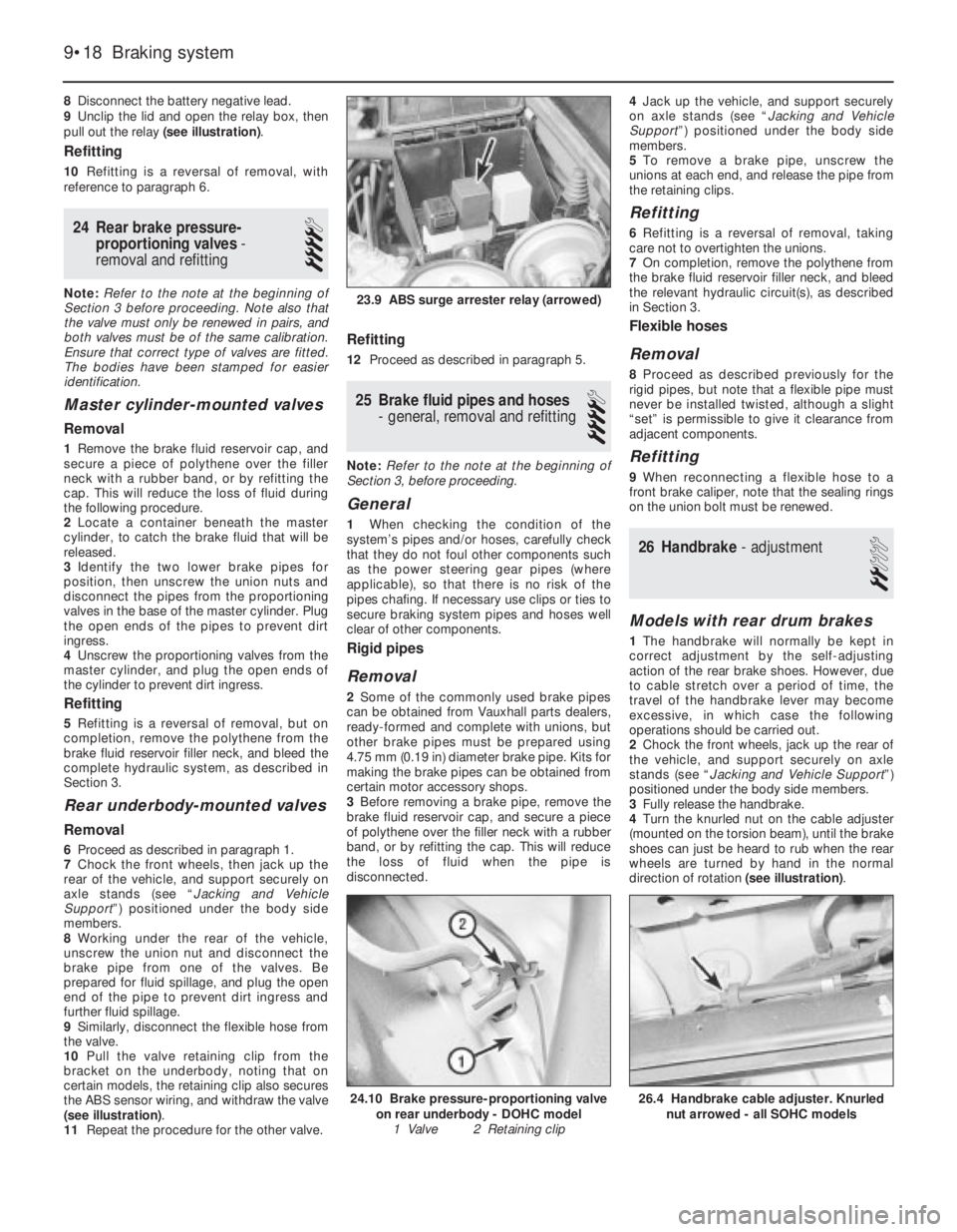
pull out the relay (see illustration).
Refitting
10Refitting is a reversal of removal, with
reference to paragraph 6.
24Rear brake pressure-
proportioning valves -
removal and refitting
4
Note: Refer to the note at the beginning of
Section 3 before proceeding. Note also that
the valve must only be renewed in pairs, and
both valves must be of the same calibration.
Ensure that correct type of valves are fitted.
The bodies have been stamped for easier
identification.
Master cylinder-mounted valves
Removal
1Remove the brake fluid reservoir cap, and
secure a piece of polythene over the filler
neck with a rubber band, or by refitting the
cap. This will reduce the loss of fluid during
the following procedure.
2Locate a container beneath the master
cylinder, to catch the brake fluid that will be
released.
3Identify the two lower brake pipes for
position, then unscrew the union nuts and
disconnect the pipes from the proportioning
valves in the base of the master cylinder. Plug
the open ends of the pipes to prevent dirt
ingress.
4Unscrew the proportioning valves from the
master cylinder, and plug the open ends of
the cylinder to prevent dirt ingress.
Refitting
5Refitting is a reversal of removal, but on
completion, remove the polythene from the
brake fluid reservoir filler neck, and bleed the
complete hydraulic system, as described in
Section 3.
Rear underbody-mounted valves
Removal
6Proceed as described in paragraph 1.
7Chock the front wheels, then jack up the
rear of the vehicle, and support securely on
axle stands (see “Jacking and Vehicle
Support”) positioned under the body side
members.
8Working under the rear of the vehicle,
unscrew the union nut and disconnect the
brake pipe from one of the valves. Be
prepared for fluid spillage, and plug the open
end of the pipe to prevent dirt ingress and
further fluid spillage.
9Similarly, disconnect the flexible hose from
the valve.
10Pull the valve retaining clip from the
bracket on the underbody, noting that on
certain models, the retaining clip also secures
the ABS sensor wiring, and withdraw the valve
(see illustration).
11Repeat the procedure for the other valve.
Refitting
12Proceed as described in paragraph 5.
25Brake fluid pipes and hoses
- general, removal and refitting
4
Note: Refer to the note at the beginning of
Section 3, before proceeding.
General
1When checking the condition of the
system’s pipes and/or hoses, carefully check
that they do not foul other components such
as the power steering gear pipes (where
applicable), so that there is no risk of the
pipes chafing. If necessary use clips or ties to
secure braking system pipes and hoses well
clear of other components.
Rigid pipes
Removal
2Some of the commonly used brake pipes
can be obtained from Vauxhall parts dealers,
ready-formed and complete with unions, but
other brake pipes must be prepared using
4.75 mm (0.19 in) diameter brake pipe. Kits for
making the brake pipes can be obtained from
certain motor accessory shops.
3Before removing a brake pipe, remove the
brake fluid reservoir cap, and secure a piece
of polythene over the filler neck with a rubber
band, or by refitting the cap. This will reduce
the loss of fluid when the pipe is
disconnected.4Jack up the vehicle, and support securely
on axle stands (see “Jacking and Vehicle
Support”) positioned under the body side
members.
5To remove a brake pipe, unscrew the
unions at each end, and release the pipe from
the retaining clips.
Refitting
6Refitting is a reversal of removal, taking
care not to overtighten the unions.
7On completion, remove the polythene from
the brake fluid reservoir filler neck, and bleed
the relevant hydraulic circuit(s), as described
in Section 3.
Flexible hoses
Removal
8Proceed as described previously for the
rigid pipes, but note that a flexible pipe must
never be installed twisted, although a slight
“set” is permissible to give it clearance from
adjacent components.
Refitting
9When reconnecting a flexible hose to a
front brake caliper, note that the sealing rings
on the union bolt must be renewed.
26Handbrake - adjustment
2
Models with rear drum brakes
1The handbrake will normally be kept in
correct adjustment by the self-adjusting
action of the rear brake shoes. However, due
to cable stretch over a period of time, the
travel of the handbrake lever may become
excessive, in which case the following
operations should be carried out.
2Chock the front wheels, jack up the rear of
the vehicle, and support securely on axle
stands (see “Jacking and Vehicle Support”)
positioned under the body side members.
3Fully release the handbrake.
4Turn the knurled nut on the cable adjuster
(mounted on the torsion beam), until the brake
shoes can just be heard to rub when the rear
wheels are turned by hand in the normal
direction of rotation (see illustration).
9•18Braking system
23.9 ABS surge arrester relay (arrowed)
26.4 Handbrake cable adjuster. Knurled
nut arrowed - all SOHC models24.10 Brake pressure-proportioning valve
on rear underbody - DOHC model
1 Valve 2 Retaining clip
Page 164 of 525
regulator vacuum pipe should be routed over
the top of the camshaft cover breather hoses.
21On models with the Multec system note
also the following:
a)Fit the new diaphragm so that it locates in
the throttle body groove.
b)Ensure that the spring and spring seat are
correctly engaged with each other and
with the diaphragm and regulator cover.
Then press the cover over its locating
dowels and hold it in place while the
screws are tightened.
c)Tighten the screws carefully to the
specified torque wrench setting.
22On completion, check the regulator for
leaks, pressurising the system by switching
the ignition on and off several times, before
the engine is started.
22Idle speed adjuster - removal
and refitting
3
Note:Idle speed adjustment on models fitted
with Multec systems, is not possible, as it is
controlled by the ECU. Refer to Section 1.
Removal
SOHC models (except Multec system)
1Disconnect the battery negative lead.
2Disconnect the wiring plug from the idle
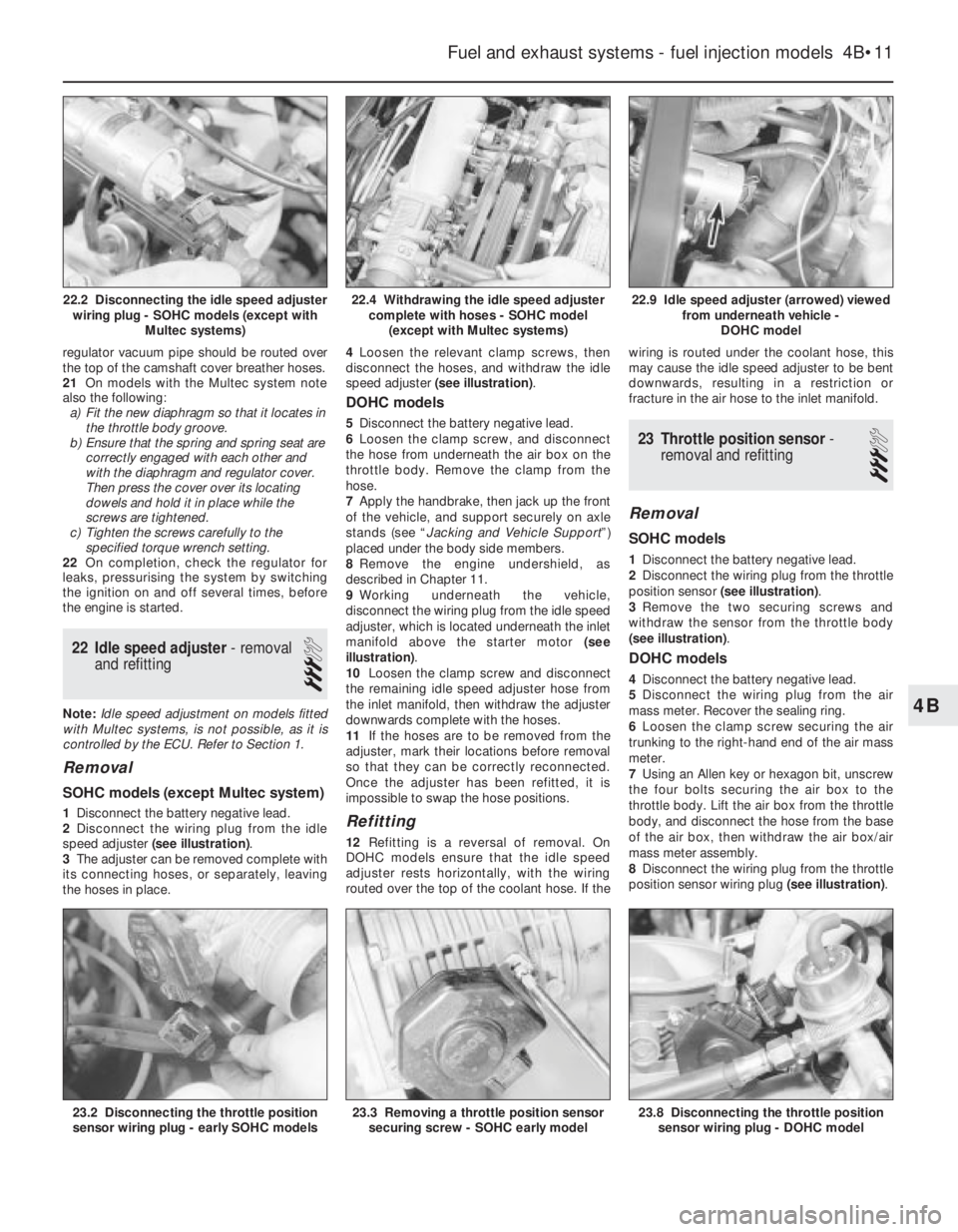
speed adjuster (see illustration).
3The adjuster can be removed complete with
its connecting hoses, or separately, leaving
the hoses in place.4Loosen the relevant clamp screws, then
disconnect the hoses, and withdraw the idle
speed adjuster (see illustration).
DOHC models
5Disconnect the battery negative lead.
6Loosen the clamp screw, and disconnect
the hose from underneath the air box on the
throttle body. Remove the clamp from the
hose.
7Apply the handbrake, then jack up the front
of the vehicle, and support securely on axle
stands (see “Jacking and Vehicle Support”)
placed under the body side members.
8Remove the engine undershield, as
described in Chapter 11.
9Working underneath the vehicle,
disconnect the wiring plug from the idle speed
adjuster, which is located underneath the inlet
manifold above the starter motor (see
illustration).
10Loosen the clamp screw and disconnect
the remaining idle speed adjuster hose from
the inlet manifold, then withdraw the adjuster
downwards complete with the hoses.
11If the hoses are to be removed from the
adjuster, mark their locations before removal
so that they can be correctly reconnected.
Once the adjuster has been refitted, it is
impossible to swap the hose positions.
Refitting
12Refitting is a reversal of removal. On
DOHC models ensure that the idle speed
adjuster rests horizontally, with the wiring
routed over the top of the coolant hose. If thewiring is routed under the coolant hose, this
may cause the idle speed adjuster to be bent
downwards, resulting in a restriction or
fracture in the air hose to the inlet manifold.
23Throttle position sensor -
removal and refitting
3
Removal
SOHC models
1Disconnect the battery negative lead.
2Disconnect the wiring plug from the throttle
position sensor (see illustration).
3Remove the two securing screws and
withdraw the sensor from the throttle body
(see illustration).
DOHC models
4Disconnect the battery negative lead.
5Disconnect the wiring plug from the air
mass meter. Recover the sealing ring.
6Loosen the clamp screw securing the air
trunking to the right-hand end of the air mass
meter.
7Using an Allen key or hexagon bit, unscrew
the four bolts securing the air box to the
throttle body. Lift the air box from the throttle
body, and disconnect the hose from the base
of the air box, then withdraw the air box/air
mass meter assembly.
8Disconnect the wiring plug from the throttle
position sensor wiring plug (see illustration).
Fuel and exhaust systems - fuel injection models 4B•11
22.9 Idle speed adjuster (arrowed) viewed
from underneath vehicle -
DOHC model
23.8 Disconnecting the throttle position
sensor wiring plug - DOHC model23.3 Removing a throttle position sensor
securing screw - SOHC early model23.2 Disconnecting the throttle position
sensor wiring plug - early SOHC models
22.4 Withdrawing the idle speed adjuster
complete with hoses - SOHC model
(except with Multec systems)22.2 Disconnecting the idle speed adjuster
wiring plug - SOHC models (except with
Multec systems)
4B
Page 166 of 525
28Fuel injectors (except Multec
system) - removal and refitting
3
Note:Refer to Section 2 before proceeding.
New O-rings must be used when refitting the
injectors. Where applicable, a tachometer and
an exhaust gas analyser will be required to
check the idle mixture on completion
Removal
SOHC models
1Disconnect the battery negative lead.
2Unscrew the union nut, and disconnect the
brake servo vacuum hose from the inlet
manifold.
3Remove the idle speed adjuster, complete
with hoses, referring to Section 22 if
necessary.4Disconnect the vacuum pipe from the top
of the fuel pressure regulator.
5Disconnect the wiring harness housing from
the fuel injectors, and move it to one side,
taking care not to strain the wiring. Pull up on
the wiring harness housing, and compress the
wiring plug retaining clips to release the
harness housing from the injectors.
6Remove the four bolts from the brackets
securing the fuel rail to the inlet manifold, then
lift the fuel rail complete with fuel injectors
sufficiently to enable the injector(s) to be
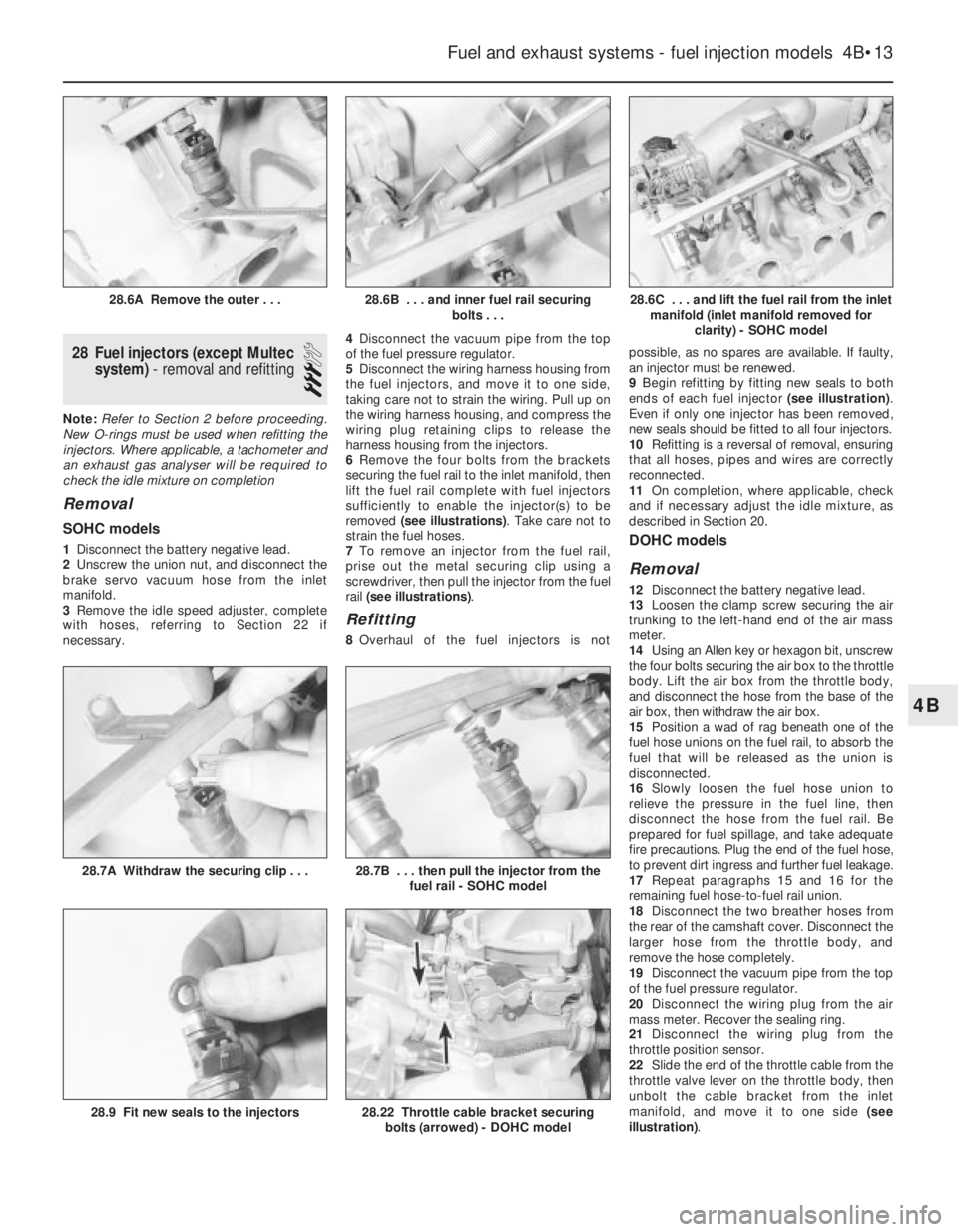
removed (see illustrations). Take care not to
strain the fuel hoses.
7To remove an injector from the fuel rail,
prise out the metal securing clip using a
screwdriver, then pull the injector from the fuel
rail (see illustrations).
Refitting
8Overhaul of the fuel injectors is notpossible, as no spares are available. If faulty,
an injector must be renewed.
9Begin refitting by fitting new seals to both
ends of each fuel injector (see illustration).
Even if only one injector has been removed,
new seals should be fitted to all four injectors.
10Refitting is a reversal of removal, ensuring
that all hoses, pipes and wires are correctly
reconnected.
11On completion, where applicable, check
and if necessary adjust the idle mixture, as
described in Section 20.
DOHC models
Removal
12Disconnect the battery negative lead.
13Loosen the clamp screw securing the air
trunking to the left-hand end of the air mass
meter.
14Using an Allen key or hexagon bit, unscrew
the four bolts securing the air box to the throttle
body. Lift the air box from the throttle body,
and disconnect the hose from the base of the
air box, then withdraw the air box.
15Position a wad of rag beneath one of the
fuel hose unions on the fuel rail, to absorb the
fuel that will be released as the union is
disconnected.
16Slowly loosen the fuel hose union to
relieve the pressure in the fuel line, then
disconnect the hose from the fuel rail. Be
prepared for fuel spillage, and take adequate
fire precautions. Plug the end of the fuel hose,
to prevent dirt ingress and further fuel leakage.
17Repeat paragraphs 15 and 16 for the
remaining fuel hose-to-fuel rail union.
18Disconnect the two breather hoses from
the rear of the camshaft cover. Disconnect the
larger hose from the throttle body, and
remove the hose completely.
19Disconnect the vacuum pipe from the top
of the fuel pressure regulator.
20Disconnect the wiring plug from the air
mass meter. Recover the sealing ring.
21Disconnect the wiring plug from the
throttle position sensor.
22Slide the end of the throttle cable from the
throttle valve lever on the throttle body, then
unbolt the cable bracket from the inlet
manifold, and move it to one side (see
illustration).
Fuel and exhaust systems - fuel injection models 4B•13
28.6C . . . and lift the fuel rail from the inlet
manifold (inlet manifold removed for
clarity) - SOHC model
28.22 Throttle cable bracket securing
bolts (arrowed) - DOHC model28.9 Fit new seals to the injectors
28.7B . . . then pull the injector from the
fuel rail - SOHC model28.7A Withdraw the securing clip . . .
28.6B . . . and inner fuel rail securing
bolts . . .28.6A Remove the outer . . .
4B
Page 170 of 525
Refitting
5Refitting is a reversal of the removal
procedure, ensuring that the wiring plugs are
correctly reconnected and that the unit is
located securely.
36Knock sensor and module
(X16 SZ models) - removal
and refitting
3
Removal
1The knock sensor fitted to the X16 SZ
engine is located on the cylinder block below
the inlet manifold, between cylinders 2 and 3.
2Disconnect the battery negative lead.
3Remove the wiring and unscrew the unit
from the block.
4The module and control unit are located on
the left-hand side of the engine compartment
behind the battery. To remove, disconnect the
wiring multiplug and remove the retaining
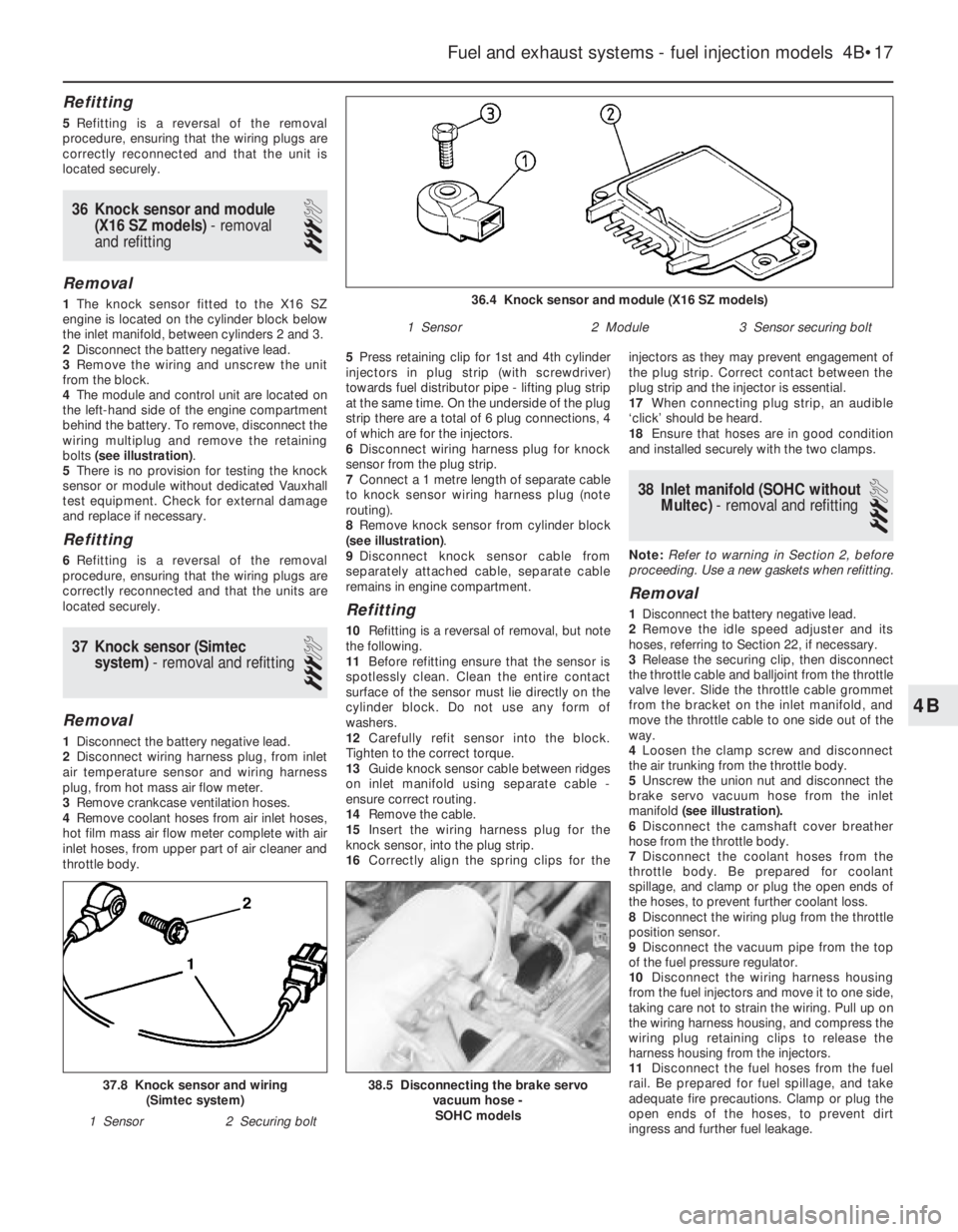
bolts (see illustration).
5There is no provision for testing the knock
sensor or module without dedicated Vauxhall
test equipment. Check for external damage
and replace if necessary.
Refitting
6Refitting is a reversal of the removal
procedure, ensuring that the wiring plugs are
correctly reconnected and that the units are
located securely.
37Knock sensor (Simtec
system) - removal and refitting
3
Removal
1Disconnect the battery negative lead.
2Disconnect wiring harness plug, from inlet
air temperature sensor and wiring harness
plug, from hot mass air flow meter.
3Remove crankcase ventilation hoses.
4Remove coolant hoses from air inlet hoses,
hot film mass air flow meter complete with air
inlet hoses, from upper part of air cleaner and
throttle body.5Press retaining clip for 1st and 4th cylinder
injectors in plug strip (with screwdriver)
towards fuel distributor pipe - lifting plug strip
at the same time. On the underside of the plug
strip there are a total of 6 plug connections, 4
of which are for the injectors.
6Disconnect wiring harness plug for knock
sensor from the plug strip.
7Connect a 1 metre length of separate cable
to knock sensor wiring harness plug (note
routing).
8Remove knock sensor from cylinder block
(see illustration).
9Disconnect knock sensor cable from
separately attached cable, separate cable
remains in engine compartment.
Refitting
10Refitting is a reversal of removal, but note
the following.
11Before refitting ensure that the sensor is
spotlessly clean. Clean the entire contact
surface of the sensor must lie directly on the
cylinder block. Do not use any form of
washers.
12Carefully refit sensor into the block.
Tighten to the correct torque.
13Guide knock sensor cable between ridges
on inlet manifold using separate cable -
ensure correct routing.
14Remove the cable.
15Insert the wiring harness plug for the
knock sensor, into the plug strip.
16Correctly align the spring clips for theinjectors as they may prevent engagement of
the plug strip. Correct contact between the
plug strip and the injector is essential.
17When connecting plug strip, an audible
‘click’ should be heard.
18Ensure that hoses are in good condition
and installed securely with the two clamps.
38Inlet manifold (SOHC without
Multec) - removal and refitting
3
Note:Refer to warning in Section 2, before
proceeding. Use a new gaskets when refitting.
Removal
1Disconnect the battery negative lead.
2Remove the idle speed adjuster and its
hoses, referring to Section 22, if necessary.
3Release the securing clip, then disconnect
the throttle cable and balljoint from the throttle
valve lever. Slide the throttle cable grommet
from the bracket on the inlet manifold, and
move the throttle cable to one side out of the
way.
4Loosen the clamp screw and disconnect
the air trunking from the throttle body.
5Unscrew the union nut and disconnect the
brake servo vacuum hose from the inlet
manifold(see illustration).
6Disconnect the camshaft cover breather
hose from the throttle body.
7Disconnect the coolant hoses from the
throttle body. Be prepared for coolant
spillage, and clamp or plug the open ends of
the hoses, to prevent further coolant loss.
8Disconnect the wiring plug from the throttle
position sensor.
9Disconnect the vacuum pipe from the top
of the fuel pressure regulator.
10Disconnect the wiring harness housing
from the fuel injectors and move it to one side,
taking care not to strain the wiring. Pull up on
the wiring harness housing, and compress the
wiring plug retaining clips to release the
harness housing from the injectors.
11Disconnect the fuel hoses from the fuel
rail. Be prepared for fuel spillage, and take
adequate fire precautions. Clamp or plug the
open ends of the hoses, to prevent dirt
ingress and further fuel leakage.
Fuel and exhaust systems - fuel injection models 4B•17
38.5 Disconnecting the brake servo
vacuum hose -
SOHC models37.8 Knock sensor and wiring
(Simtec system)
1 Sensor2 Securing bolt
36.4 Knock sensor and module (X16 SZ models)
1 Sensor2 Module3 Sensor securing bolt
4B